Your browser does not fully support modern features. Please upgrade for a smoother experience.
Please note this is an old version of this entry, which may differ significantly from the current revision.
Multilevel inverters (MLI) consist of a wide range of power converters. They have many designs and have been introduced with different circuit topologies such as neutral point clamped, diode clamped, cascaded H-bridges, and flying capacitors. Some of these MLIs have disadvantages, including design complexity, size, and losses due to the large number of switching devices required when they produce many output voltage levels. They are also bulky in size and may require several DC power sources.
- inverter
- multilevel
- PWM
- SHE
1. Simple Designs
T-MLIs are considered simplified NPC MLI. Per phase, a T-MLI consists of two conventional switching devices and one bidirectional switching device, as shown in Figure 1b. Figure 2 shows how a T-MLI single-phase MLI is originated from a traditional two-level full-bridge inverter. This is performed by substituting the two-level switching device arm with a three-level T-type arm. The T-branch consists of S1, S2, S3, and S4 IGBTs. Switching is performed at high frequency to perform SPWM modulation, and the two-stage branch (S5 to S6) switches at the fundamental frequency, which is either 60 or 50 Hz, to change the polarity of the output voltage. Since the structure is symmetric, only the positive half-wave of the power supply is analyzed [1].
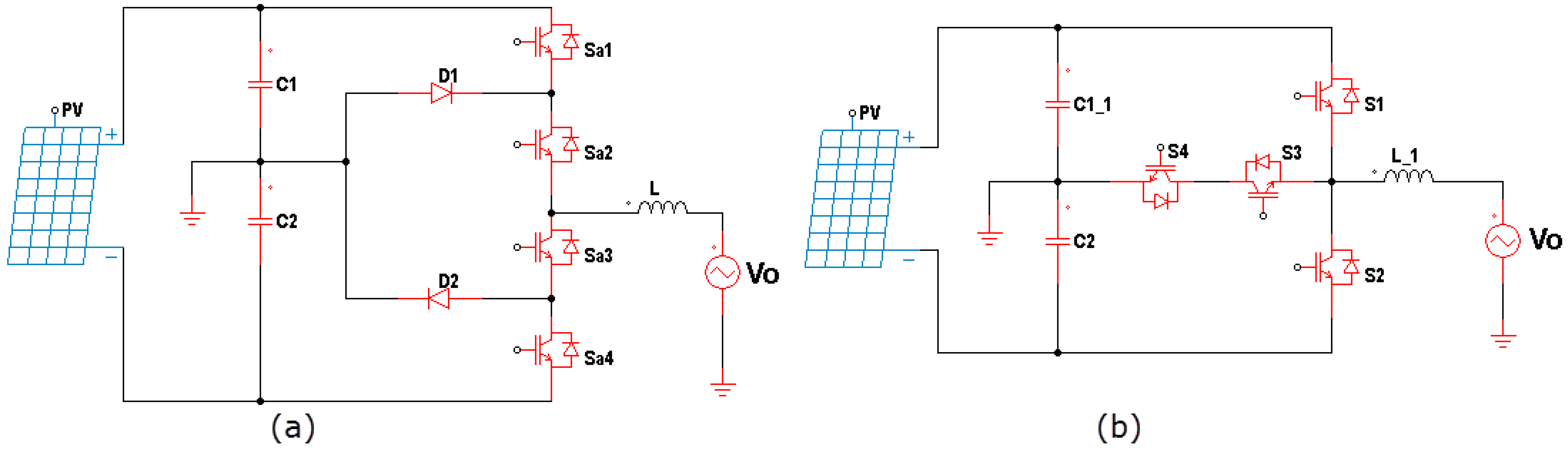
Figure 1. Single-phase three-level (a) NPC MLI (b) T-MLI.
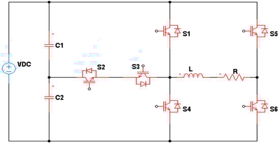
Figure 2. A single-phase T-type five-level inverter.
C1 and C2 should be balanced in capacitance and voltage. Thus, usually, they are selected with high values. Each capacitance is responsible for feeding the full or an equal portion of the supplied DC voltage to the load. S2 and S3 are responsible for the levels, where S2 is ON for the positive part and S3 is ON for the negative part. S1 and S5 are responsible for the levels, where S1 is ON for the positive part and S5 is ON for the negative part. S4 and S6 can be ON or OFF when supplying or where S6 Is ON for the positive part and S4 is ON for the negative part of the full or half DC voltage. The MLI in Figure 2 is a five-level inverter since the voltage levels are arranged as ( , . For a seven-level type, the number of DC side capacitors is increased to three. Also, there will be two S2 and S3 branches, or (T-branches) where each is connected between two capacitors. The HB side remains the same. Thus, the number of switching devices is increased by two. The voltage levels for the seven-level T-MLI are ( , .
A small modification of the seven-level T-MLI was previously performed, where five levels were proposed by [2][3]. In this design, blocking diodes D5 to D8 are added to secure unwanted current flow and reduce the output voltage ripple as well as its harmonics, as shown in Figure 3. The operation modes are illustrated in Figure 4.
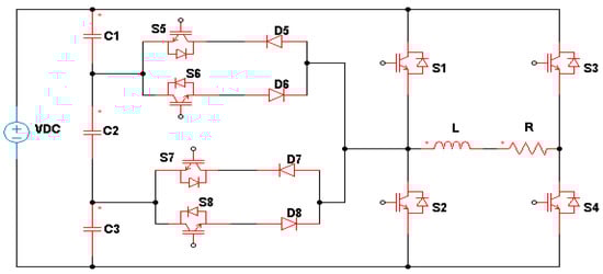
Figure 3. T-type seven-level inverter with blocking diodes.
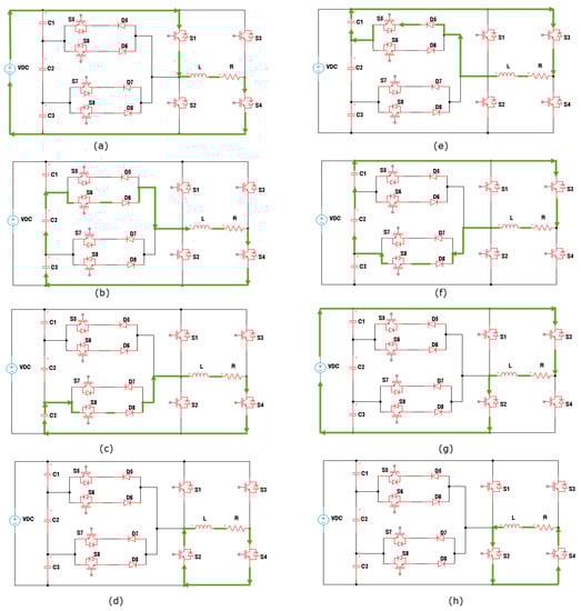
Figure 4. Modes of operation of a seven-level inverter for the modes: (a) , (b) .
For a seven-level T-MLI, another design is shown in Figure 5 [4][5]. This design is similar to the five-level inverter in Figure 1. The difference is that the HB portion is connected to the S3 and S4 branches. In this scheme, only two capacitors on the DC bus are needed instead of three as compared to [2]. Both designs have the same number of switching devices.
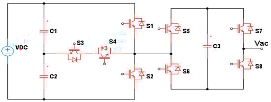
Figure 5. Another Seven-level inverter topology.
The T-branch of the five-level inverter of Figure 2 can be replaced with a bidirectional switch known as a transistor-clamped inverter. The switch is constructed from a single switching device bounded by four diodes [6][7]. This type of inverter was formerly known as a modified HB MLI [8]. In this design, the number of switching devices is reduced by 16.66%. In the case of a seven-level inverter, the number of IGBT switches is decreased by 25% since only six will be needed instead of eight.
A modified converter similar to the structure of the MLI in Figure 3 was proposed [9]. This MLI has two isolated DC sources or capacitors and uses eight bidirectional conduction switching devices. A bidirectional conduction scheme is used for switching devices, but due to the presence of an anti-parallel diode, it only blocks voltage in one direction. The proposed topology allows the use of two separate DC sources, either from PV systems, battery banks, or rectifier circuits. An improved five-level T-MLI was developed based on the method of hysteresis current (HC) to control the inverter [10]. The hysteresis levels are used to provide switching signals for the transistors in T-MLIs. This design is similar to those in Figure 2 and Figure 6, but the T-branch contains only one bidirectional switch consisting of two IGBTs connected at their gates. This inverter has only two balancing capacitors on its DC link side. The switches in the T-branch of a five-level inverter can be replaced by a short circuit and are not connected to the HB [5]. There are two switching transistors connected in parallel to the HB, and the T-branch is connected to both switching transistors. Also, there are two transistors connected in series with the DC source at their ends. In this inverter, the number of switching devices is increased by 33.33% for the MLI in Figure 2 and by 60% for the MLI in Figure 6.
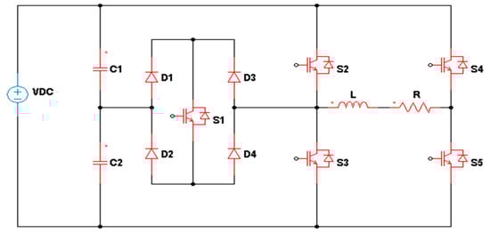
Figure 6. Five-level inverter with a bidirectional switch.
The topology of the three-level inverter includes an HB inverter and two bidirectional switching devices, as shown in Figure 7. Its five-level version is included as well [11]. The bidirectional switches are linked to the HB to generate the third stage of the inverter output. Other IGBTs are incorporated into the inverter circuit to increase the number of levels. The two portions of this MLI operate at high and low frequencies, resulting in a multi-level hybrid switching frequency T-MLI. Here, the switching devices in the HB work at a 50 Hz switching frequency. The bidirectional switching devices can work at frequencies up to 10 kHz [12].
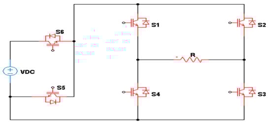
Figure 7. Three-level inverter.
A five-level inverter structure is illustrated in Figure 8. This inverter includes four capacitors (C1–C4), eight power switches, and two diodes (D1, D2) [13]. The mechanism of this topology is according to the switched capacitor principle. The T-structure of the inverter topology has four switches (S1, S2, S21, and S22). Output voltage polarity is determined through switches S1 and S2. SU1, SU2, SL1, and SL2 are responsible for increasing the number of levels of the output voltage from three to five. In comparison with the inverter in Figure 2, the number of switching elements is increased by 33.33%.
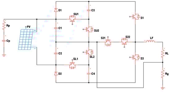
Figure 8. A five-level inverter with eight switches.
Another modified T-MLI topology is presented in Figure 9 [13]. The basic module is illustrated in Figure 9a, whereas the construction of a five-level inverter is shown in Figure 9b. There are four DC sources, which can be substituted by balancing capacitors, and the number of switching devices is eight. From this design, the neutral is located at point N. Point (A) represents the output side, which is connected to the load when the switching devices , are in the ON state. The performance of this five-level inverter modification is due to the and switches. When are in the ON state, they must tolerate negative voltages.
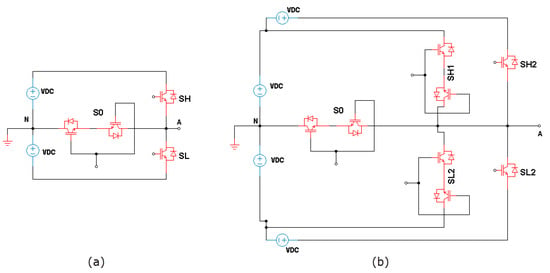
Figure 9. Modified T-MLI, (a) the proposed module, and (b) a five-level version.
2. Complex Designs
Normally, the complex designs of T-MLIs are accompanied with an increase in the number of levels of the MLI output voltage to more than seven. Generally, most of the simple topologies of Section 3.1 can be maximized as nine-level inverters or even more levels [14]. A nine-level inverter is proposed in [15] and shown in Figure 10. It is based on the cascading modules of a T-type switched capacitor. The switched capacitors are enabled by a step-by-step charging method to attain voltage gain and high levels of output voltage. Furthermore, the inversion process is achieved without using an HB portion, which greatly decreases the number of switches. The proposed topology of this nine-level inverter can be constructed using only ten switches. Voltage gain is increased by two times. The nine levels of the output voltage are arranged as ( .
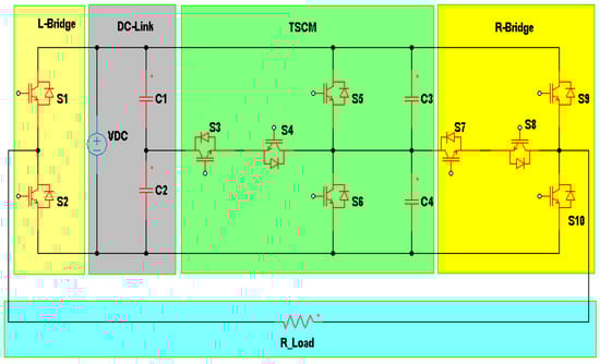
Figure 10. A nine-level inverter based on cascading of T-Type modules.
A basic segment is formed by a back-to-back (BTB) connection with a modified T-shaped and half-bridge inverter (BBTHB), as shown in Figure 11a [16]. The HB portion of an inverter is linked to points A and B, which are shown in Figure 11b. There are five DC power sources at different voltage levels. The concept of this topology is to fabricate a new MLI structure with more output voltage levels but utilizing fewer switching devices. The proposed power circuit of the BBTHB module is shown in Figure 11c. This inverter topology can generate up to 31 voltage levels with five DC power sources using 12 power switches. It can provide negative levels without involving an HB. Table 1 illustrates the possible ON and OFF states of this T-type inverter. This topology exhibits in both the negative and positive voltage levels through switches , and . Simply, the voltage drop at the switches is due to a conduction process. Unidirectional switches , and are activated in the reverse modes to avoid shorting the DC power supply.
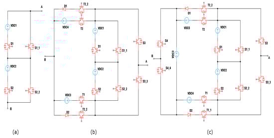
Figure 11. A modified T-MLI, (a) modified T-type converter, (b) modified T-type inverter, and (c) BBTHB proposed structure.
Table 1. Output voltage and switch status for a modified 15-level T-MLI.
| Level of the Output Voltage | S1 | S2 | S3 | T1 | T1_1 | T2 | T2_2 |
|---|---|---|---|---|---|---|---|
| 1 | 1 | 1 | 1 | 0 | 0 | 0 | |
| 1 | 0 | 1 | 1 | 0 | 0 | 0 | |
| 1 | 1 | 0 | 1 | 0 | 0 | 0 | |
| 1 | 0 | 0 | 1 | 0 | 0 | 0 | |
| 1 | 1 | 1 | 0 | 1 | 0 | 0 | |
| 1 | 0 | 1 | 0 | 1 | 0 | 0 | |
| 1 | 1 | 0 | 0 | 1 | 0 | 0 | |
| 0 | 1 | 0 | 0 | 0 | 1 | 0 | 0 |
| 0 | 1 | 0 | 0 | 1 | 0 | 1 | |
| 0 | 0 | 1 | 0 | 0 | 0 | 1 | |
| 0 | 1 | 1 | 1 | 1 | 0 | 1 | |
| 1 | 0 | 0 | 0 | 0 | 1 | 0 | |
| 0 | 1 | 0 | 0 | 0 | 1 | 0 | |
| 1 | 0 | 1 | 0 | 0 | 1 | 0 | |
| 0 | 1 | 1 | 0 | 0 | 1 | 0 |
The topology proposed by [17] introduces a hybrid T-Type (HT) type MLI. This topology consists of 12 diodes and switching devices and five DC power sources. Eleven voltage levels can be generated by this MLI, which are (one zero-level, five negative-levels, and five positive-levels) in a symmetric configuration with no HB module.
The concept of this topology utilizes different sides of the DC power sources to create different routes that are coupled with the other DC sources, as shown in Figure 12. The switch set ( ) is coupled with the (VC3M) DC source. Nearby switches ( ) work together for different levels of voltage generation. S9 and S10 are bidirectional switches mounted in both T-type modules at each side to prevent short-circuiting between the four DC sources (VDC1L, VDC2L, VDC1R, and VDC2R).
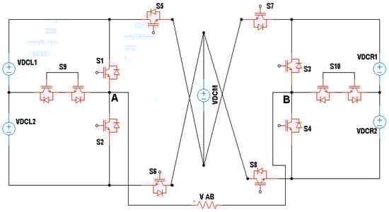
Figure 12. A single-phase 11-level HT-type multilevel inverter.
In [18], there is an MLI that shows some structural similarity to the proposed topology in [17], but using three modules. T-type modules are located at each end of the topology, denoted as T and T’. Switching devices, Sti and Sti’ where (i = 1...5), are utilized in these modules. Other modules, or switching devices, are positioned between the T-type configurations using interconnecting structures for scalable topologies. To step up the MLI AC voltage N times, several DC sources are required, [(N/2) − 1], with a cross module for each module and two capacitors.
The work of [19] presents a new and different module for asymmetric MLI inverters with fewer elements. This involves a square arrangement of two BTB T-MLIs with other switching devices. A square T-type (ST-type) portion creates seventeen levels using twelve switching devices and four different DC supplies having two voltage levels (three VDC and one VDC). The two strategies can also be expanded in a cascading arrangement to achieve even more levels. ST-type modules can be formed by connecting two T-connectors BTB from points A, B, and C. This means one bidirectional switch from point B, and two unidirectional switching devices should be added from points C and A, as shown in Figure 13. The intermediate circuits are assumed to have respective voltages of one VDC and three VDC for the first and second T-connections. This design is used for an MLI (with different ratios of intermediate circuits) to produce various numbers of output voltage levels and fewer switching devices.
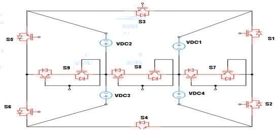
Figure 13. ST-Type module of multilevel inverter.
Table 2 represents a comparison among the different T-Type MLIs that are discussed. A comparison is made between the number of switching devices for each MLI topology, the number of DC sources, the number of DC-link capacitors, the availability of switching modules, and blocking diodes. Some of the topologies can be extended for a higher number of levels (N) as in [1][2][4][6][11], but others are intended for the proposed number of levels [13][14][15][16][17][19]. Also, most of them have to balance the voltage across DC capacitors connected with a single DC source. In the rest of the topologies, DC capacitors are replaced by several DC sources. Few of them have switching modules, which are a combination of two opposite switching devices triggered by a single pulse at the same time. Each switch is an IGBT connected with an anti-parallel diode. Blocking diodes are also employed in most of the topologies to control the current path for the required instantaneous voltage level. The efficient inverter topology is that which has a low number of components and provides a possibly high number of levels for its output voltage. The selection of the efficient inverter topology is tied to that which has a low number of components and provides a possibly high number of levels for its output voltage.
Table 2. Comparison between different T-Type MLI topologies.
| Ref. No. | Number of Switching Devices | Number of Voltage Sources |
Number of DC-Link Capacitors | Switching Modules | Blocking Diodes |
|---|---|---|---|---|---|
| [1] | 1 | No | No | ||
| [2] | 1 | No | Yes | ||
| [4] | 1 | No | No | ||
| [6] | 1 | Yes | Yes | ||
| [11] | No | No | No | ||
| [12] | 8 for five-level | 1 | 2 | No | Yes |
| [13] | 8 for five-level | 4 for five-level | No | Yes | Yes |
| [15] | 10 for nine-level | 1 | 4 for nine-level | No | No |
| [16] | 12 for fifteen-level | 4 for fifteen-level | No | No | Yes |
| [17] | 12 for eleven-level | 4 for eleven-level | No | No | No |
| [19] | 12 for seventeen-level | 4 for seventeen-level | No | Yes | Yes |
This entry is adapted from the peer-reviewed paper 10.3390/en15228720
References
- Zhang, Z.; Zhang, J.; Wu, X. A single phase T-type inverter operating in boundary conduction mode. In Proceedings of the 2016 IEEE Energy Conversion Congress and Exposition (ECCE), Milwaukee, WI, USA, 18–22 September 2016; pp. 1–6.
- Mohammed, M.F.; Ahmad, A.H.; Humod, A.T. Design and Simulation of a New Seven Levels Inverter for Renewable Energy Sources. J. Eng. Appl. Sci. 2018, 13, 6866–6872.
- Mohammed, M.F.; Ahmad, A.H.; Humod, A.T. Harmonics reduction of a five-level inverter by unbalanced carriers and over-modulation techniques. Int. J. Eng. Technol. 2018, 7, 1059–1063.
- Yu, H.; Chen, B.; Yao, W.; Lu, Z. Hybrid Seven-Level Converter Based on T-Type Converter and H-Bridge Cascaded Under SPWM and SVM. IEEE Trans. Power Electron. 2018, 33, 689–702.
- Jacob, J.T.; Kirubakaran, D. A Hybrid T-Type Multilevel Inverter with A Novel Modulation Strategy for Isolated Supply Electric Systems. J. Eng. Sci. Technol. 2019, 14, 1614–1638.
- Ceglia, G.; Guzman, V.; Sanchez, C.; Ibanez, F.; Walter, J.; Gimenez, M.I. A New Simplified Multilevel Inverter Topology for DC–AC Conversion. IEEE Trans. Power Electron. 2006, 21, 1311–1319.
- Bhaskar, M.S.; Almakhles, D.; Padmanaban, S.; Ionel, D.M.; Blaabjerg, F.; He, J.; Kumar, A.R. Investigation of a Transistor Clamped T-Type Multilevel H-Bridge Inverter With Inverted Double Reference Single Carrier PWM Technique for Renewable Energy Applications. IEEE Access 2020, 8, 161787–161804.
- Rahim, N.A.; Chaniago, K.C.; Selvarage, J. A modified H Bridge Multilevel Inverter for Photovoltaic System. IEICE Elecronic Express 2010, 7, 751–758.
- Sudheer, D.S.; Reddy, S.; Kumar, J.S.; Ayyapparaju, C.B.; Reddy, M.S. A Single-Phase Inverter Topology with Seven-Level Output based on T-type Structure. In Proceedings of the 2021 6th International Conference for Convergence in Technology (I2CT), Maharashtra, India, 2–4 April 2021; pp. 1–4.
- Mustafa, I.N.C.I. Performance Analysis of T-type Inverter Based on Improved Hysteresis Current Controller. Balk. J. Electr. Comput. Eng. 2019, 7, 147–155.
- Karthik, K.I.N.; Srinivasa Rao, S. Five-Level Inverter Using POD PWM Technique. In Proceedings of the International Conference on Electrical, Electronics, Signals, Communication and Optimization (EESCO), Visakhapatnam, India, 24–25 January 2015; pp. 1–6.
- Sunddararaj, S.P.; Rangarajan, S.S.; Subashini, N.; Subramaniam, U.; Collins, E.R.; Senjyu, T. A novel T-Type Multilevel Inverter for Electric Vehicle and Grid-connected applications. In Proceedings of the 2021 7th International Conference on Electrical Energy Systems (ICEES), Chennai, India, 11–13 February 2021; pp. 166–170.
- Dhara, S.; Hota, A.; Jain, S.; Agarwal, V. A Novel Single-Phase T-Type PV Inverter with Improved DC Utilization. In Proceedings of the 2018 IEEE International Conference on Power Electronics, Drives and Energy Systems (PEDES), Chennai, India, 18–21 December 2018; pp. 1–5.
- Ouchatti, A.; Majdoul, R.; Moutabir, A.; Taouni, A.; Touati, A. Modified T-type topology of three-phase multi-level inverter for photovoltaic systems. Int. J. Electr. Comput. Eng. 2022, 12, 262–268.
- Wang, Y.; Yuan, Y.; Li, G.; Chen, T.; Wang, K.; Liang, J. A Generalized Multilevel Inverter Based on T-Type Switched Capacitor Module with Reduced Devices. Energies 2020, 13, 4406.
- Hosseinzadeh, M.A.; Sarbanzadeh, M.; Sarebanzadeh, E.; Rivera, M.; Munoz, J. Reduced modified T-type topology for cascaded multilevel inverters. In Proceedings of the 2018 IEEE International Conference on Automation/XXIII Congress of the Chilean Association of Automatic Control (ICA-ACCA), Concepcion, Chile, 17–19 October 2018; pp. 1–6.
- Meraj, S.T.; Yahaya, N.Z.; Hasan, K.; Masaoud, A. A hybrid T-type (HT-type) multilevel inverter with reduced components. Ain Shams Eng. J. 2021, 12, 1959–1971.
- Khenar, M.; Taghvaie, A.; Adabi, J. Multi-level inverter with combined T-type and cross-connected modules. IET Power Electron. 2018, 11, 1407–1415.
- Samadaei, E.; Sheikholeslami, A.; Gholamian, S.A.; Adabi, J. A Square T-Type (ST-Type) Module for Asymmetrical Multilevel Inverters. IEEE Trans. Power Electron. 2018, 33, 987–996.
This entry is offline, you can click here to edit this entry!