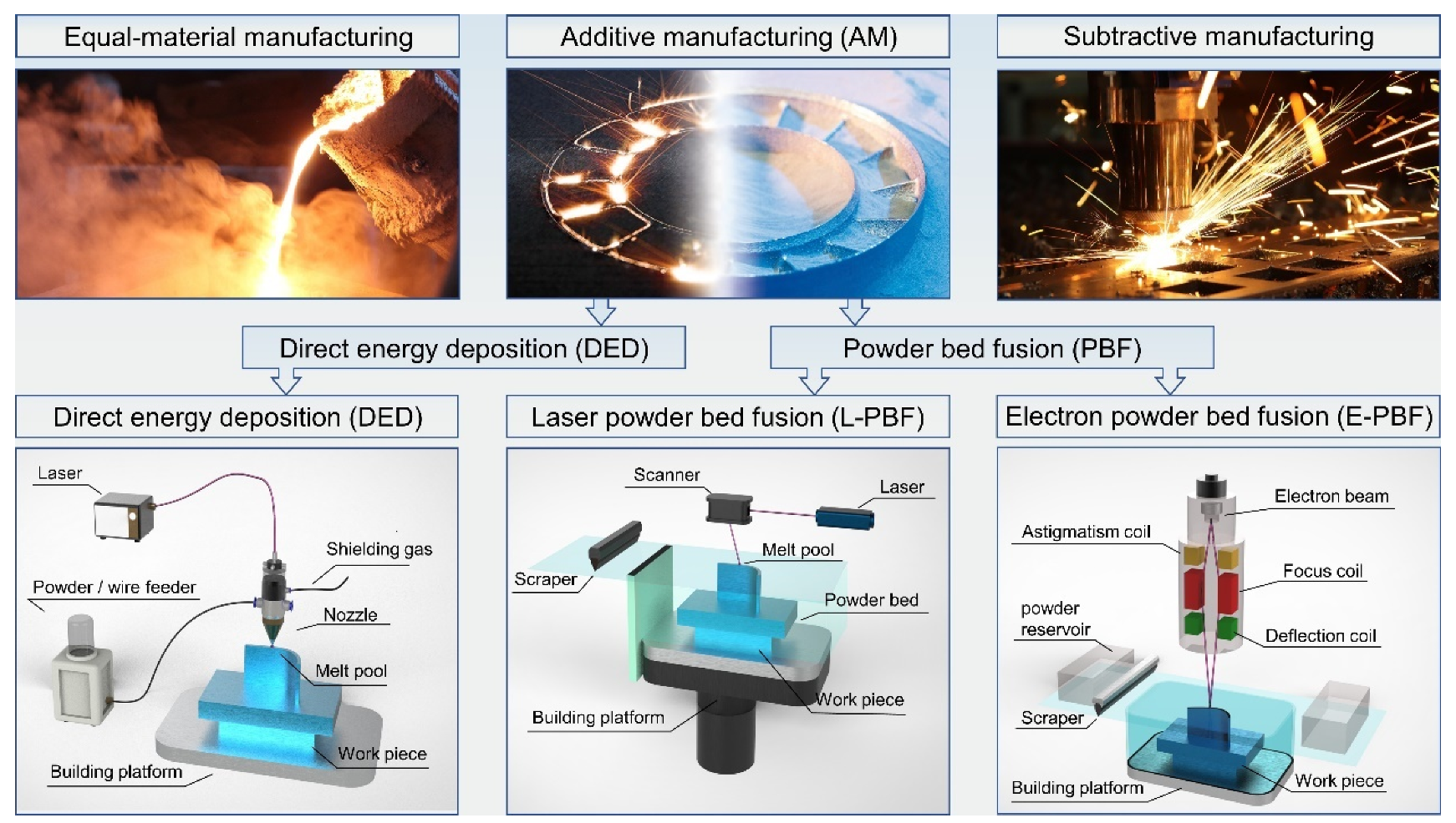
Spatter is an inherent, unpreventable, and undesired phenomenon in laser powder bed fusion (L-PBF) additive manufacturing. Spatter, metal vapor and molten pool are important physical phenomena in laser-matter interaction. During L-PBF, the spatter formation mechanism can be demonstrated as the hot spatter ejection mainly driven by the instability of the molten pool due to the vapor-induced recoil pressure, and the cold spatter ejection mainly driven by the vapor-induced entrainment of the shielding gas. Spatter behavior has an intrinsic correlation with the forming quality in L-PBF because it leads to metallurgical defects and the degradation of mechanical properties. This impact becomes more severe in the fabrication of large-sized parts during the multi-laser L-PBF process. Therefore, investigations of spatter generation and countermeasures have become more urgent.
- spatter
- laser powder bed fusion
- in situ detection
- generation mechanism
1. Introduction
2. Laser Powder Bed Fusion Spatter In Situ Detection Device
2.1. Visible-Light High-Speed Detector
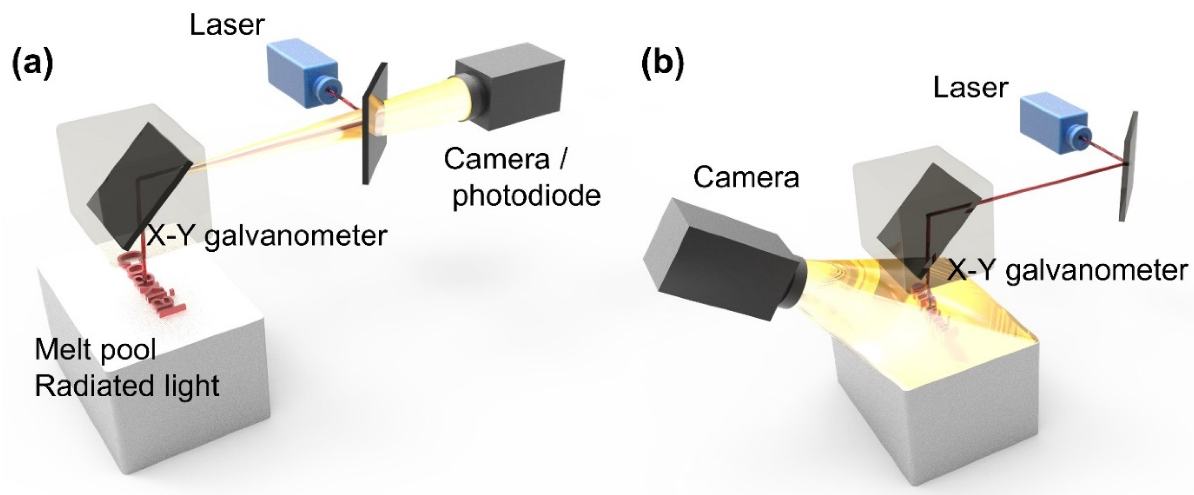
2.2. Invisible-Light In Situ Detection
2.3. Data Processing during Spatter Detection
2.4. Full-Cycle Detection of Spatter in L-PBF
-
Initial stage (generation, adjacent to the melt pool): The positions of the generation of both the cold spatters and hot spatters are adjacent to the melt pool. The ultra-high-frame-rate in situ detection using a high-temporal-spatial-resolution off-axis camera combined with the illumination light source can obtain a clear morphology of spatters, which helps to reveal the mechanism of the spatter generation.
-
Flight stage (ejection, away from the powder bed): The amount of spatter and the ejection angle significantly affect the internal defect of the part. The spatter trajectory, ejection velocity, ejection angle, and spatter size of the spatter should be obtained to investigate the intrinsic correlation between the spatter and the defect. A long monitoring time, high-frame-rate in situ detection system, along with the laser path using multi-sensors, is applied to capture the spatter flight (even with 3D information). The high-throughput data during L-PBF process can be used for the statistics analysis of spatter characterization. In general, only hot spatters are detected in this stage to reduce the processing pressure of the monitoring system.
-
Fall-back stage (re-deposition, close to the powder bed): The spatter eventually redeposits on the powder bed and parts, which affect re-coating and part quality. A layer-by-layer in situ detection with a wide field-of-view and high-spatial-resolution camera can obtain high quality images of the powder and parts. The image data employing algorithms extract and confirm the size and location of the redeposited spatter, which helps in predicting the forming quality of the parts and the location of the defect.
2.5. Differences In Situ Detection between Spatter and Melt Pool
- (1)
-
Compared with the detection of the melt pool, the spatter, with a micro size and extensive range of motion in the 3D space, is much more difficult to be detected, which requires multiple sensors, up to four sensors, with micron spatial resolution.
- (2)
-
Additionally, the melt pool is generated by the action of the laser in the metal powder bed, and its trajectory can be predicted according to the pre-defined laser path. In contrast, the trajectory of spatter is hard to be predicted due to the high-speed random motion in the 3D space, which requires sensors with a higher temporal resolution up to microseconds to detect the whole process of motion trajectory deflection.
- (3)
-
The data of spatter collected using sensors with high spatial resolution and high temporal resolution are several orders larger than the data of melt pool detection. Therefore, the data processing of spatter detection is more complex, which puts higher demands on the algorithm.
3. Mechanism of Spatter Generation
3.1. Spatter Classification
3.2. Study of Droplet Spatter Ejected from “Liquid Base” of Melt Pool
3.3. Study of Powder Spatter Ejected from “Solid Base” of Substrate
3.4. Study of Spatter Generation Mechanism in Multi-Laser-PBF Fabrication Process
4. Disadvantage of Spatter
5. Spatter Countermeasures
5.1. Process Parameters
5.2. Equipment and Materials for L-PBF
| Materials | Spatter Countermeasures | References | |
|---|---|---|---|
| L-PBF equipment | 316L, Aluminum |
Uniformity of flow field | Philo et al. (2018) [61] Xiao et al. (2021) [62] |
| 316L | Prevent powder from blowing away | Zhang et al. (2020) [63] | |
| 316L | High gravity powder bed | Koike et al. (2021) [64][65] | |
| Powder materials | 316L, 13-93 bioactive glass | Increasing the viscosity of melt | Leung et al. (2018) [66] |
| AISI 4130; 316L | Reducing the oxygen content of powder | Heiden et al. (2019) [67] Fedina et al. (2020) [68] Fedina et al. (2021) [69] |
6. Conclusions
- (1)
-
In situ detection system for spatter during L-PBF: The detection methods are based on the physical properties (trajectory and brightness) of the spatter and melt pool. The variances in the trajectory and brightness lead to differences in the sensors and light sources of the detection system.
-
Sensor: Due to the complex and unpredictable trajectories of the spatters in the 3D space compared to the melt pool, detection requires multiple sensors and sophisticated algorithms. A 3D detection solution with a quadruple-eye sensor combined with algorithms has been applied in a visible-light detection system. The emergence of 3D detection solutions provides more information in three dimensions, which improves the accuracy of the spatter detection.
-
Light source: Compared to the bright high-temperature melt pool, the spatters consist of both bright hot droplet spatters and dark cold powder spatters. The motion of dark cold powder spatter can hardly be captured without an external light source. Therefore, a visible light source must be applied to enable the detecting of two types of spatters.
-
- (2)
-
Mechanism of spatter generation in L-PBF: spatter can be divided into droplet spatter from the “liquid base” of the melt pool and powder spatter from the “solid base” of the substrate.
-
Droplet spatter from the “Liquid base” of the melt pool: The droplet spatter originates from the instability of the melt pool. The Marangoni effect and the metal vapor recoil pressure generated on the surface of the melt pool lead to the spatter ejection from “liquid base” of the melt pool.
-
Powder spatter from the “Solid base” of the substrate: Powder spatter is induced by the entrainment effect of the ambient gas flow driven by the metal vapor. A low-pressure area is generated near the high-speed moving metal vapor, and the surrounding inert protective gas will be “entrained” to the vicinity of the melt pool, driving the powder spatter to be ejected from the “solid base” of the substrate.
-
- (3)
-
Spatter effects during L-PBF: Spatter has negative effects not only on the equipment and quality of parts, but also on the whole life cycle of the powder. Therefore, spatter significantly affects both the current L-PBF manufacturing and the subsequent L-PBF manufacturing.
-
Equipment: the laser light path will be obstructed by the ejected spatter, and the scraper will be damaged by the redeposited spatter.
-
Current L-PBF manufacturing: redeposited spatter can cause deterioration in the part structure and mechanical property.
-
Subsequent L-PBF manufacturing: the spatters redeposit into the powder bed to be inclusions, resulting in a decrease in the quality of the re-cycle powder and affecting the subsequent L-PBF manufacturing.
-
- (4)
-
Countermeasures for spatter in L-PBF: for the full cycle of spatter (generation–ejection–redeposition), the countermeasures for spatter are divided into spatter generation suppression and spatter removal.
-
Spatter generation suppression: the generation of spatter can be suppressed by optimizing the laser volumetric energy density (e.g., raising the scanning velocity, lowering the laser power, decreasing the layer thickness, and increasing the laser spot), laser beam mode (Bessel beams), and pressure of the building chamber.
-
Spatter removal efficiency: The gas flow removes process by-products from the process zone to enable an undisturbed process. Simulation framework methods (CFD and DEM) and a full-scale geometric model are employed to optimize the flow filed structure. A high-velocity gas flow under a certain value (counter-Coanda effect) applied in the center of the powder bed greatly improves the efficiency of spatter removal.
-
This entry is adapted from the peer-reviewed paper 10.3390/mi13081366
References
- DebRoy, T.; Mukherjee, T.; Wei, H.L.; Elmer, J.W.; Milewski, J.O. Metallurgy, mechanistic models and machine learning in metal printing. Nat. Rev. Mater. 2020, 6, 48–68.
- Gu, D.; Shi, X.; Poprawe, R.; Bourell, D.L.; Setchi, R.; Zhu, J. Material-structure-performance integrated laser-metal additive manufacturing. Science 2021, 372, eabg1487.
- MacDonald, E.; Wicker, R. Multiprocess 3D printing for increasing component functionality. Science 2016, 353, aaf2093.
- Wei, H.; Mukherjee, T.; Zhang, W.; Zuback, J.; Knapp, G.; De, A.; DebRoy, T. Mechanistic models for additive manufacturing of metallic components. Prog. Mater. Sci. 2020, 116, 100703.
- Office of the Under Secretary of Defense, Research and Engineering (USD(R&E)). Department of Defense Additive Manufacturing Strategy. Available online: https://www.cto.mil/dod-additive-manufacturing-strategy/ (accessed on 3 May 2022).
- U.S. Department of Defense. DoD Instruction 5000.93, “Use of Additive Manufacturing in the DoD”. Available online: https://www.defense.gov/News/News-Stories/Article/Article/2712969/dod-promotes-additive-manufacturing-expansion-standardization-training-through/ (accessed on 3 May 2022).
- National Science and Technology Information System, Public Service Platform. The 2022 Annual Project Application Guide for the Key Projects of Additive Manufacturing and Laser Manufacturing Under the 14th Five-Year National Key R&D Program. Available online: https://service.most.gov.cn/kjjh_tztg_all/20220427/4894.html (accessed on 3 May 2022).
- Yang, Y. Analysis of Classifications and Characteristic of Additive Manufacturing (3D Print). Adv. Aeronaut. Sci. Eng. 2019, 10, 309–318. (In Chinese)
- Lu, B.H.; Li, D.C. Development of the additive manufacturing (3D printing) technology. Mach. Build. Autom. 2013, 42, 1–4. (In Chinese)
- Ian Gibson, D.R. Brent Stucker. Additive Manufacturing Technologies 3D Printing, Rapid Prototyping, and Direct Digital Manufacturing; Springer: New York, NY, USA, 2015.
- Frazier, W.E. Metal additive manufacturing: A review. J. Mater. Eng. Perform. 2014, 23, 1917–1928.
- Mellor, S.; Hao, L.; Zhang, D. Additive manufacturing: A framework for implementation. Int. J. Prod. Econ. 2014, 149, 194–201.
- Zhang, L.; Li, Y.; Li, S.; Gong, P.; Chen, Q.; Geng, H.; Sun, M.; Sun, Q.; Hao, L. Fabrication of Titanium and Copper-Coated Diamond/Copper Composites via Selective Laser Melting. Micromachines 2022, 13, 724.
- Wang, X.; Jiang, J.; Tian, Y. A Review on Macroscopic and Microstructural Features of Metallic Coating Created by Pulsed Laser Material Deposition. Micromachines 2022, 13, 659.
- Xu, Z.; Wang, D.; Song, W.; Tang, C.; Sun, P.; Yang, J.; Hu, Q.; Zeng, X. Microstructure and Wear of W-Particle-Reinforced Al Alloys Prepared by Laser Melt Injection. Micromachines 2022, 13, 699.
- Cardon, A.; Mareau, C.; Ayed, Y.; Van Der Veen, S.; Giraud, E.; Santo, P.D. Heat treatment simulation of Ti-6Al-4V parts produced by selective laser melting. Addit. Manuf. 2020, 39, 101766.
- Bartlett, J.L.; Li, X. An overview of residual stresses in metal powder bed fusion. Addit. Manuf. 2019, 27, 131–149.
- Grasso, M. In Situ Monitoring of Powder Bed Fusion Homogeneity in Electron Beam Melting. Materials 2021, 14, 7015.
- Sun, S.; Brandt, M.; Easton, M. Powder bed fusion processes: An overview. Laser Addit. Manuf. 2017, 55–77.
- King, W.E.; Anderson, A.T.; Ferencz, R.M.; Hodge, N.E.; Kamath, C.; Khairallah, S.A.; Rubenchik, A.M. Laser powder bed fusion additive manufacturing of metals; physics, computational, and materials challenges. Appl. Phys. Rev. 2015, 2, 041304.
- Ji, H.R.; Zhao, M.C.; Xie, B.; Zhao, Y.C.; Yin, D.F.; Gao, C.D.; Shuai, C.J.; Atrens, A. Corrosion and antibacterial performance of novel selective-laser-melted (SLMed) Ti-xCu biomedical alloys. J. Alloy. Compd. 2021, 864, 158415.
- Aachen Center for Additive Manufacturing. Seminar 3D Printing with SLM – Challenges for Prediction of Deformation and Integration in Industrial Process Chains on 16 May 2017. Available online: https://acam.rwth-campus.com/news/seminar-3d-printing-with-slm-on-may-16-2017/ (accessed on 3 May 2022).
- Liu, Y.; Meng, J.; Zhu, L.; Chen, H.; Li, Z.; Li, S.; Wang, D.; Wang, Y.; Kosiba, K. Dynamic compressive properties and underlying failure mechanisms of selective laser melted Ti-6Al-4V alloy under high temperature and strain rate conditions. Addit. Manuf. 2022, 54, 102772.
- Wang, W.; Takata, N.; Suzuki, A.; Kobashi, M.; Kato, M. Microstructural Variations in Laser Powder Bed Fused Al–15%Fe Alloy at Intermediate Temperatures. Materials 2022, 15, 4497.
- Zhang, X.; Chueh, Y.-H.; Wei, C.; Sun, Z.; Yan, J.; Li, L. Additive manufacturing of three-dimensional metal-glass functionally gradient material components by laser powder bed fusion with in situ powder mixing. Addit. Manuf. 2020, 33, 101113.
- Song, C.; Hu, Z.; Xiao, Y.; Li, Y.; Yang, Y. Study on Interfacial Bonding Properties of NiTi/CuSn10 Dissimilar Materials by Selective Laser Melting. Micromachines 2022, 13, 494.
- Grasso, M.; Colosimo, B.M. Process defects and in situ monitoring methods in metal powder bed fusion: A review. Meas. Sci. Technol. 2017, 28, 044005.
- Zhao, C.; Fezzaa, K.; Cunningham, R.W.; Wen, H.; De Carlo, F.; Chen, L.; Rollett, A.D.; Sun, T. Real-time monitoring of laser powder bed fusion process using high-speed X-ray imaging and diffraction. Sci. Rep. 2017, 7, 3602.
- Fabbro, R. Melt pool and keyhole behaviour analysis for deep penetration laser welding. J. Phys. D Appl. Phys. 2010, 43, 445501.
- Sames, W.J.; List, F.A.; Pannala, S.; Dehoff, R.R.; Babu, S.S. The metallurgy and processing science of metal additive manufacturing. Int. Mater. Rev. 2016, 61, 315–360.
- Matthews, M.J.; Guss, G.; Khairallah, S.A.; Rubenchik, A.M.; Depond, P.J.; King, W.E. Denudation of metal powder layers in laser powder bed fusion processes. Acta Mater. 2016, 114, 33–42.
- Yadroitsev, I.; Gusarov, A.; Yadroitsava, I.; Smurov, I. Single track formation in selective laser melting of metal powders. J. Mater. Process. Technol. 2010, 210, 1624–1631.
- Riedlbauer, D.; Scharowsky, T.; Singer, R.F.; Steinmann, P.; Körner, C.; Mergheim, J. Macroscopic simulation and experimental measurement of melt pool characteristics in selective electron beam melting of Ti-6Al-4V. Int. J. Adv. Manuf. Technol. 2016, 88, 1309–1317.
- Bidare, P.; Bitharas, I.; Ward, R.; Attallah, M.; Moore, A.J. Laser powder bed fusion in high-pressure atmospheres. Int. J. Adv. Manuf. Technol. 2018, 99, 543–555.
- Tan, Z.; Fang, Q.; Li, H.; Liu, S.; Zhu, W.; Yang, D. Neural network based image segmentation for spatter extraction during laser-based powder bed fusion processing. Opt. Laser Technol. 2020, 130, 106347.
- Eschner, E.; Staudt, T.; Schmidt, M. 3D particle tracking velocimetry for the determination of temporally resolved particle trajectories within laser powder bed fusion of metals. Int. J. Extreme Manuf. 2019, 1, 035002.
- Liu, Y.; Yang, Y.; Mai, S.; Wang, D.; Song, C. Investigation into spatter behavior during selective laser melting of AISI 316L stainless steel powder. Mater. Des. 2015, 87, 797–806.
- Khairallah, S.A.; Anderson, A.T.; Rubenchik, A.; King, W.E. Laser powder-bed fusion additive manufacturing: Physics of complex melt flow and formation mechanisms of pores, spatter, and denudation zones. Acta Mater. 2016, 108, 36–45.
- Khairallah, S.A.; Martin, A.A.; Lee, J.R.I.; Guss, G.; Calta, N.P.; Hammons, J.A.; Nielsen, M.H.; Chaput, K.; Schwalbach, E.; Shah, M.N.; et al. Controlling interdependent meso-nanosecond dynamics and defect generation in metal 3D printing. Science 2020, 368, 660–665.
- Altmeppen, J.; Nekic, R.; Wagenblast, P.; Staudacher, S. Transient simulation of particle transport and deposition in the laser powder bed fusion process: A new approach to model particle and heat ejection from the melt pool. Addit. Manuf. 2021, 46, 102135.
- Ly, S.; Rubenchik, A.M.; Khairallah, S.A.; Guss, G.; Matthews, M.J. Metal vapor micro-jet controls material redistribution in laser powder bed fusion additive manufacturing. Sci. Rep. 2017, 7, 4085.
- Leung, C.L.A.; Marussi, S.; Atwood, R.C.; Towrie, M.; Withers, P.; Lee, P.D. In situ X-ray imaging of defect and molten pool dynamics in laser additive manufacturing. Nat. Commun. 2018, 9, 1355.
- Chen, H.; Yan, W. Spattering and denudation in laser powder bed fusion process: Multiphase flow modelling. Acta Mater. 2020, 196, 154–167.
- Andani, M.T.; Dehghani, R.; Karamooz-Ravari, M.R.; Mirzaeifar, R.; Ni, J. Spatter formation in selective laser melting process using multi-laser technology. Mater. Des. 2017, 131, 460–469.
- Yin, J.; Wang, D.; Wei, H.; Yang, L.; Ke, L.; Hu, M.; Xiong, W.; Wang, G.; Zhu, H.; Zeng, X. Dual-beam laser-matter interaction at overlap region during multi-laser powder bed fusion manufacturing. Addit. Manuf. 2021, 46, 102178.
- Nassar, A.R.; Gundermann, M.A.; Reutzel, E.; Guerrier, P.; Krane, M.H.; Weldon, M.J. Formation processes for large ejecta and interactions with melt pool formation in powder bed fusion additive manufacturing. Sci. Rep. 2019, 9, 5038.
- Wang, D.; Wu, S.; Fu, F.; Mai, S.; Yang, Y.; Liu, Y.; Song, C. Mechanisms and characteristics of spatter generation in SLM processing and its effect on the properties. Mater. Des. 2017, 117, 121–130.
- Spierings, A.; Herres, N.; Levy, G. Influence of the particle size distribution on surface quality and mechanical properties in AM steel parts. Rapid Prototyp. J. 2011, 17, 195–202.
- Li, R.; Shi, Y.; Wang, Z.; Wang, L.; Liu, J.; Jiang, W. Densification behavior of gas and water atomized 316L stainless steel powder during selective laser melting. Appl. Surf. Sci. 2010, 256, 4350–4356.
- Kruth, J.P.; Froyen, L.; Van Vaerenbergh, J.; Mercelis, P.; Rombouts, M.; Lauwers, B. Selective laser melting of iron-based powder. J. Mater. Processing Technol. 2004, 149, 616–622.
- Schwerz, C.; Raza, A.; Lei, X.; Nyborg, L.; Hryha, E.; Wirdelius, H. In-situ detection of redeposited spatter and its influence on the formation of internal flaws in laser powder bed fusion. Addit. Manuf. 2021, 47, 102370.
- Sutton, A.T.; Kriewall, C.S.; Leu, M.C.; Newkirk, J.W.; Brown, B. Characterization of laser spatter and condensate generated during the selective laser melting of 304L stainless steel powder. Addit. Manuf. 2019, 31, 100904.
- Aucott, L.; Dong, H.; Mirihanage, W.; Atwood, R.; Kidess, A.; Gao, S.; Wen, S.; Marsden, J.; Feng, S.; Tong, M.; et al. Revealing internal flow behaviour in arc welding and additive manufacturing of metals. Nat. Commun. 2018, 9, 1–7.
- Wang, D.; Ye, G.; Dou, W.; Zhang, M.; Yang, Y.; Mai, S.; Liu, Y. Influence of spatter particles contamination on densification behavior and tensile properties of CoCrW manufactured by selective laser melting. Opt. Laser Technol. 2019, 121, 105678.
- Sartin, B.; Pond, T.; Griffith, B.; Everhart, W.; Elder, L.; Wenski, E.; Cook, C.; Wieliczka, D.; King, W.; Rubenchik, A. 316L powder reuse for metal additive manufacturing. In Proceedings of the 2017 International Solid Freeform Fabrication Symposium, Austin, TX, USA, 7–9 August 2017; pp. 351–364.
- Delacroix, T.; Lomello, F.; Schuster, F.; Maskrot, H.; Garandet, J.-P. Influence of powder recycling on 316L stainless steel feedstocks and printed parts in laser powder bed fusion. Addit. Manuf. 2021, 50, 102553.
- Quintana, O.A.; Alvarez, J.; Mcmillan, R.; Tong, W.; Tomonto, C. Effects of Reusing Ti-6Al-4V Powder in a Selective Laser Melting Additive System Operated in an Industrial Setting. JOM 2018, 70, 1863–1869.
- Cordova, L.; Campos, M.; Tinga, T. Revealing the Effects of Powder Reuse for Selective Laser Melting by Powder Characterization. JOM 2019, 71, 1062–1072.
- Nezhadfar, P.D.; Soltani-Tehrani, A.; Sterling, A.; Tsolas, N.; Shamsaei, N. The effects of powder recycling on the mechanical properties of additively manufactured 17-4 PH stainless steel. In Proceedings of the 2018 International Solid Freeform Fabrication Symposium, Austin, TX, USA, 13–15 August 2018; pp. 1292–1300.
- He, X.; Kong, D.; Zhou, Y.; Wang, L.; Ni, X.; Zhang, L.; Wu, W.; Li, R.; Li, X.; Dong, C. Powder recycling effects on porosity development and mechanical properties of Hastelloy X alloy during laser powder bed fusion process. Addit. Manuf. 2022, 55, 102840.
- Philo, A.M.; Butcher, D.; Sillars, S.; Sutcliffe, C.J.; Sienz, J.; Brown, S.G.R.; Lavery, N.P. A Multiphase CFD Model for the Prediction of Particulate Accumulation in a Laser Powder Bed Fusion Process. In Proceedings of the CFD Modeling and Simulation in Materials Processing 2018; Springer: Cham, Switzerland, 2018; pp. 65–76.
- Xiao, J.; Xie, Y. Wind field simulation and optimization of 3D metal printing device with SLM. Mag. Equip. Mach. 2021, 2, 34–39. (In Chinese)
- Zhang, X.; Cheng, B.; Tuffile, C. Simulation study of the spatter removal process and optimization design of gas flow system in laser powder bed fusion. Addit. Manuf. 2020, 32, 101049.
- Koike, R.; Sugiura, Y. Metal powder bed fusion in high gravity. CIRP Ann. 2021, 70, 191–194.
- Sugiura, Y.; Koike, R. High-gravitational effect on process stabilization for metal powder bed fusion. Addit. Manuf. 2021, 46, 102153.
- Leung, C.L.A.; Marussi, S.; Towrie, M.; Garcia, J.D.V.; Atwood, R.C.; Bodey, A.J.; Jones, J.R.; Withers, P.J.; Lee, P.D. Laser-matter interactions in additive manufacturing of stainless steel SS316L and 13–93 bioactive glass revealed by in situ X-ray imaging. Addit. Manuf. 2018, 24, 647–657.
- Heiden, M.J.; Deibler, L.A.; Rodelas, J.M.; Koepke, J.R.; Tung, D.J.; Saiz, D.J.; Jared, B.H. Evolution of 316L stainless steel feedstock due to laser powder bed fusion process. Addit. Manuf. 2018, 25, 84–103.
- Fedina, T.; Sundqvist, J.; Powell, J.; Kaplan, A.F. A comparative study of water and gas atomized low alloy steel powders for additive manufacturing. Addit. Manuf. 2020, 36, 101675.
- Fedina, T.; Sundqvist, J.; Kaplan, A.F.H. Spattering and oxidation phenomena during recycling of low alloy steel powder in Laser Powder Bed Fusion. Mater. Today Commun. 2021, 27, 102241.