Anodizing is an electrochemical process by which the thickness of the natural oxide layer present on metals is increased. Anodizing is used to improve the corrosion and wear resistance of the substrate, to enhance the adhesion of coatings and for aesthetics reasons. The properties, chemistry and morphology of the resulting anodic oxide film depend on the anodizing parameters chosen.
- anodizing
- aluminium
- corrosion protection
- anodic layers
- anodic oxide
1.Introduction
Anodizing is an electrochemical process in which the operating conditions such as the temperature of the electrolyte and the electrode, the electrolyte pH and chemical composition, as well as the current density involved play a crucial role and influence the final properties, chemistry, and morphology of the resulting anodic oxide film. This section discusses the working principles of anodizing, the barrier and porous anodic layer types and the effect that the operating conditions have on the anodizing process itself and on the properties of the resulting anodic oxide layer.
2. Working Principles
Anodizing is an electrochemical process to artificially thicken the oxide film on a metal surface, creating an oxide layer of up to several micrometers thick. This artificial oxide film forms on aluminum when a current at sufficient voltage flows through an electrolyte in which the aluminum is the anode and a suitable material is the cathode [1]. The involved mobile species in the anodizing of pure aluminum in aqueous solutions are Al3+ cations, and O2− or OH− anions [2][3]. The oxidation of aluminum at the aluminum/oxide interface generates the Al3+ cations, while O2− or OH− anions form at the oxide/solution interface by the stripping of H+ from H2O molecules [2].
Ionic migration through the oxide under a high electric field (in the order of 108 to 109 V/m) enables the growth of the anodic oxide film [2]. The high electric field is generated by the potential drop, caused by the insulating properties of the aluminum oxide at the metal/oxide/electrolyte interface [4]. O2− and OH− anions migrate through the film towards the oxide/metal interface. Once there, they react with Al3+ cations resulting in oxide formation [3]. Some of the available Al3+ cations are not consumed at the oxide/metal interface and they migrate towards the electrolyte. At the oxide/electrolyte interface, additional alumina can be formed by the reaction of the Al3+ cations that have migrated from the oxide/metal interface with available O2− anions [3][5][6]. Under certain conditions (that will be discussed later on) the Al3+ cations are ejected into the electrolyte [4]. Ion migration and dissolution during anodizing is schematically represented in Figure 2.
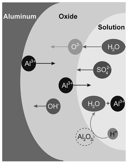
Figure 2. Schematic illustration of ions movement and dissolution of oxide in sulfuric acid solution. Reprinted with permission from [5]; Copyright 2008 John Wiley and Sons.
Besides the oxide formation reaction, other reactions, known as side reactions, related with the nature of the substrate alloy or the electrolyte, can occur and have a significant impact on the anodizing process and its efficiency. An example of this is the deposition of dissolved metals (e.g., copper) present as alloying element or the oxygen evolution reaction [7][8][9][10][11][12][13][14][15][16][17][18][19][20][21]. The effect of alloying elements, as well as the effect of the electrolyte nature will be further discussed in Sections 3.1 and 4.
Regarding the crystallinity of the anodic oxide formed, a large number of anodic coatings have been studied. It has been found that all of them consist largely of amorphous oxide, with a percentage of γ-Al2O3 formed in some cases [3][5][11][12]. In general, the lower the amount of species incorporated from the electrolyte, the higher the oxide crystallinity [13]. Still, some authors report on completely amorphous anodic oxides and attribute the γ-Al2O3 percentage to an artefact caused by the interaction of the oxide layer with the electron beam during transmission electron microscopy [3][5][14]. An effect on the anodic oxide crystallinity by the pre-treatment steps cannot be ruled out [15].
3. Barrier Anodic Layers and Porous Anodic Layers
A so-called barrier-type anodic film is grown when the anodizing is performed in pH neutral electrolytes with a relatively low reactivity towards the anodic film. In such electrolytes, e.g., borate or tartrate solutions, the formed oxide is insoluble [5]. In this conditions, no Al3+ cations are lost into the electrolyte and barrier oxides can be grown at high current efficiencies close to 100 % [4]. The current efficiency is measured by the ratio between the amount of current used for oxide formation versus the total current applied during the process [16].
During barrier anodizing the oxide layer grows at both the aluminum/oxide interface and the oxide/electrolyte interface. It was found that 60 % of the oxide growth occurs at the aluminum/oxide interface, while 40 % of the film thickness forms at the oxide/electrolyte interface, as shown in Figure 3 [2]. The growth of the film continues until the resistance of the film prevents the current from reaching the anode [15]. At this stage, the barrier-type anodic film suffers a dielectric breakdown [3]. This phenomenon gives rise to localized sparking and is reflected by voltage or current instabilities during the anodizing process [2][3].
Generally, barrier anodizing is performed at low current densities, typically between 0.01 and 1 A/dm2. The chemical composition of barrier anodic oxides is not pure alumina since electrolyte ions incorporate into the film [2][3][6]. Incorporated electrolyte species typically account for about 1 at% [2]. Furthermore, barrier films are thin (typically up to hundreds of nanometers) and dielectrically compact [5][12][15].
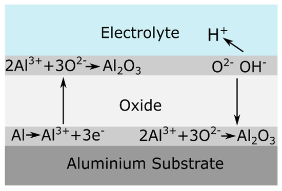
Figure 3. Schematic representation of ionic processes taking place during barrier oxide growth. Reprinted from [2]; Copyright 2009 VUBPRESS.
On the contrary, if the anodic oxide film is soluble in the electrolyte, a porous oxide film forms. These porous oxide layers are the ones relevant for aerospace applications. The pores are oriented perpendicular to the metal surface at the center of a cell and the cells ordered in a hexagonal array [3][4][5]. A thin barrier layer of scalloped morphology is present at the pore base. The morphology of an ideal porous anodic layer is schematically illustrated in Figure 4.
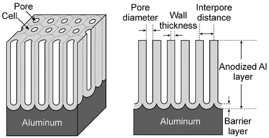
Figure 4. Schematic representation of an ideal porous anodic oxide. Reprinted with permission from [5]. Copyright 2008 John Wiley and Sons.
The barrier layer is formed first, before the porous layer growth starts. Its thickness is proportional to the applied voltage, and once formed it remains constant during the anodizing process [5]. This layer is thin enough to allow a continuous ionic flow [3]. The continuous ionic flow, together with the access of the electrolyte, and therefore of the current, to the oxide/metal interface through the porous structure, lead to a continuous film growth [15]. This does not mean that the film thickness is necessarily constantly increasing. In fact, the film growth rate gradually reduces as the electrical resistance increases with film thickness [15]. When the film growth rate is equal to the film dissolution rate, the actual film thickness will remain constant. This mechanism enables the growth of a much thicker porous anodic oxide layers compared to barrier oxides. Typical porous layers can be grown up to a few hundred microns.
When a porous anodic film is being formed, Al3+ cations do not react with O2− anions at the oxide/electrolyte interface. Instead they are ejected into the electrolyte, either by field-assisted dissolution or by field-assisted direct anion ejection [2][3][17]. Therefore, the oxide growth only takes place at the oxide/metal interface. The total process efficiency is approximately 60 % since about 40 % of the Al3+ cations are lost into the electrolyte [17][18]. As the film growth proceeds, the oxide formed is pushed away from the oxide/metal interface. This means that the outer part of the film, which is the oxide formed during the first instants of the process, is in contact with the electrolyte for the entire anodizing time. This can lead to a significant chemical attack at the outer part of the film [15]. This leads to thinning of the pore walls and to wider pore mouths. When this attack is severe, the pores in the uppermost part of the film lose their structural stability and collapse. This phenomenon is known as chalking and is characterized by a slightly white-colored powdery film with reduced hardness and lower adhesion properties.
The exact mechanism of pore formation has been a subject of debate over the last decades among the scientific community. Until recently, the most widely accepted theory explaining porous formation was the field-assisted dissolution theory that was first proposed by O’Sullivan et al. [19]. The field assisted dissolution model proposes that the constant thickness of the barrier layer, which is independent from the duration of the anodizing process, implies that an equilibrium exists between the film formation rate at the metal/oxide interface and the film dissolution rate at the oxide/electrolyte interface close to the pore base. However, taking into account the chemical dissolution rate of the oxide in the open circuit (when no current is applied), an equilibrium between film formation and film dissolution is unlikely, since the dissolution rate is several orders of magnitude smaller than the oxide formation rate [20]. Therefore, the hypothesis of the field assisted dissolution theory is that the dissolution rate of aluminum oxide increases in the presence of a high external electric field by stretching or breaking the Al–O bond [20]. This increased dissolution rate under a high electric field is then able to balance the oxide formation rate. The field assisted dissolution theory explains pore nucleation by local concentrations of the electric field, associated with defects or oxide thickness non-uniformities [20]. This theory has been recently refuted by a research group from the University of Manchester [21][22][23]. Instead, their research suggests that it is plastic flow caused by stresses present in the growing anodic oxide that is responsible for pore formation [21][22][23]. Pores, they suggest, are formed by the flow of aluminum oxide from the barrier layer towards the pore walls. This mechanism is referred to as the field assisted flow theory [21][22][23]. Different origins for this stress are reported [2]: the high electric field that is generated in the oxide, inducing a compressive electrostriction pressure [24], the difference in volume between the oxide and the consumed metal [22][26], and the migration of a large number of ionic species through the oxide [26][27][28].
The validity of the field assisted flow theory has been demonstrated by the deposition of a thin layer of tungsten, used as tracer. After anodizing, the tungsten tracer was found evenly distributed at the pore walls, indicating that the oxide flows from the barrier layer towards the pore walls [21][22][23]. However, Garcia-Vergara et al. [22] showed that this behavior is, to a certain extent, electrolyte dependent. Findings compatible with the field assisted flow theory are reported after anodizing in sulfuric acid electrolyte, while growth behavior compatible with the dissolution model was found after anodizing in borax electrolyte.
4. Effect of the Applied Voltage or the Applied Current
Anodizing processes can be carried out potentiostatically, i.e., by imposing a voltage to the system and letting it freely adjust the current; or galvanostatically, imposing a current and letting the system freely adjust the voltage. In general, increasing the applied voltage in a voltage-controlled process is equivalent to increasing the current in a current-controlled process.
Generally, an increase in potential leads to thicker anodic films with thicker barrier layers, larger pore cells and wider pores. In fact, it has been found that the thickness of the barrier layer is proportional to the formation voltage. Rates of 1.3–1.4 nm/V in the case of barrier layers and 1.2 nm/V for the barrier layer at the base of porous anodic oxide have been reported [3][5][15]. These rates are considered almost universal. Other anodizing parameters seem to have little to no effect on the barrier layer thickness [3][4][5][15].
When anodizing potentiostatically, the applied voltage can be changed during the process. When a large voltage variation is applied, the oxide film morphology will adapt to the new conditions [15] and a transition from the oxide formed under the previous and the new conditions takes place. This transition varies depending on whether the change is a sudden potential drop or a sudden potential increase. In the case of a potential drop, a so called recovery effect takes place [15]. When the voltage is suddenly dropped, the current reduces to a very low value and it can take a long period of time, in the range of minutes, for the current to recover and reach the steady-state condition corresponding to the new voltage [15]. On the contrary, if the voltage is slowly reduced the current will adjust to the new condition much faster [15]. Besides the rate at which the potential is dropped, other factors influence the speed of current recovery, such as the values of the original and final voltage, the difference between voltages, and the temperature of the electrolyte [15][29]. The recovery effect is often related to the initial chemical thinning of the barrier layer, followed by a stage of field assisted dissolution in which the film is dissolved faster but also a certain degree of growth takes place at the metal/film interface. Finally, a new steady porous growth state is achieved. The observed current reduction is attributed to the delay between the applied potential and the thickness of the barrier layer underneath the pores [29][30]. From a morphological perspective van Put et al. [31] and Curioni et al. [30] showed that an oxide with varying morphology across its thickness is achieved when the potential is dropped during the process, with finer pores generated below the initially present larger pores.
Conversely, when the potential is increased, a current overshoot is observed and a new steady rate of film growth is reached relatively quickly [30]. The anodizing efficiency increases during a potential rise, because for a certain period of time the current exceeds the equilibrium current at the steady-state [31]. In this case, also a graded morphology is reported [30]. This is schematically visualized in Figure 5.
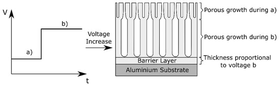
Figure 5. Schematic representation of the morphology effect of voltage variations during anodizing.
During processes of stepwise application of voltage, the thickness of the individual layers formed during each step correlates with the voltage applied [32]. Curioni et al. [30] explored this to create funneled morphologies on AA2024 T3 alloys anodized in 0.46 M sulfuric acid with the addition of 80 g/L tartaric acid in order to improve the anti-corrosion properties, as well as the adhesion performance. The desired morphology consists of an external region with a coarser morphology to improve paint adhesion, and an innermost region with a very fine and highly ordered morphology in order to hinder the penetration of a corrosive electrolyte. A transition area between the two regions should be present to prevent interfacial mechanical stresses. Such a morphology is achieved by applying an initial stage of potentiostatic anodizing at high potential, followed by a decreasing linear polarization to the final reduced potential and, finally, prolonged potentiostatic anodizing at the reduced potential. The main constraints on the design of a stepwise potential cycle are the minimum and maximum voltages applied during the low potential and high potential phases and the rate at which the potential is decreased [30]. The minimum potential needs to be sufficient to ensure the oxidation of second phase particles [32]. If the voltage is not high enough to oxidize the second phase particles, these remain in the oxide/alloy interface after anodizing and could serve as cathodic sites, enabling galvanic coupling and corrosion [30]. The effect of second phase particles during anodizing will be further discussed in Section 3.1. On the other hand, the maximum potential cannot exceed the potential leading to the onset of burning [2][30][33]. At voltages higher than a certain threshold burning takes place. Burning is a local film thickening phenomenon caused by a local current concentration and a local temperature increase [34][35]. The nature of the electrolyte determines the maximum anodizing voltage that is applicable before the onset of burning [30]. During burning a highly ordered pore arrangement is observed. This highly-ordered pore arrangement already appears at voltages slightly below the potential threshold [33]. This observation indicates that a very high electric field is the governing factor for the growth of a highly-ordered porous film [33]. According to Aerts [2], burning only takes place during the pore development phase, not in the first stages of anodizing when a compact barrier layer is formed. He suggests that burning is associated with a barrier layer thickness threshold. As previously mentioned, the barrier layer thickness is proportional to the formation voltage. Hence, a maximum barrier layer thickness implies a maximum potential that can be applied to avoid burning. Finally, during a stepwise potential change, the rate at which the potential is varied should be gentle enough to create a gradual transition between the internal fine oxide and the coarse morphology of the external oxide. Immersion experiments of anodic layers with a funneled-like morphology show promising results in pitting corrosion resistance; however, the effect of such a morphology on coating adhesion has not been reported [30].
An interesting alternative process to obtain a funnel-like structure is discussed by Chung et al. [36]. They propose the application of a small negative potential (−2 V) after DC anodizing. The hydrogen ions, positively charged, are attracted towards the surface and dissolve the anodic oxide in the uppermost region of the oxide, thereby widening the pore mouths. Moreover, there are no electrons involved in the dissolution reaction of alumina, so that no extra Joule’s heat is generated when applying the negative potential. To the authors’ knowledge, this possibility has not been further investigated, and therefore no information on its corrosion protection or adhesion performance is available.
Up to this point only the use of direct current (DC) has been discussed. Another aspect that has been investigated is the usage of alternating current (AC) for anodizing purposes. In general, AC and DC anodic layers are very similar in terms of morphology or chemical composition [37]. One important difference between AC and DC anodizing process is the evolution of hydrogen gas at the anode (the aluminum part) during the cathodic cycles [15][37][38]. For example, an alternate current at 50 Hz interrupts the oxide growth every 0.01 s, hydrogen gas evolves on the alloy surface for 0.01 s before the oxide growth reaction is resumed [37]. To obtain a comparable thickness, longer AC anodizing times are required compared to DC anodizing, since in AC processes the oxide growth is continuously interrupted. Additionally, at the beginning of each anodic cycle part of the current is used to build-up the high electric field that enables ionic migration so that oxide growth can start [37]. Consequently, part of the anodic charge is lost to processes other than oxide formation, further reducing the anodizing efficiency [37]. A maximum frequency exists, at which all the charge during the anodic cycle is consumed to build-up the electric field across the barrier layer and no oxide growth takes place [37].
For application in aerospace industry, a patent filled by Short Brothers [38] and subsidized by Bombardier claims a combination of an AC and DC process in a sulfuric and phosphoric acid mixed electrolyte, creating an oxide with a duplex structure. The outer part of the film consists of a porous structure with an average pore diameter in the range of 20–40 nm and a thickness of less than 1 µm. Underneath this outer layer, a less porous oxide with a thickness of up to 8 µm is formed. The objective of creating this duplex layer is the same as for the funnelled morphologies, aiming to optimize the adhesion of an organic coating by promoting mechanical interlocking and primer penetration into the open porous upper part of the oxide layer, while at the same time keeping a good barrier corrosion protection provided by the less porous oxide in the inner part of the film. Besides the Short Brothers patent [38], no other reference to such a duplex AC-DC oxide layer or process has been found.
5. Step Anodizing: Complex Anodic Layers
Complex anodic oxide layers can also be formed by a two-step anodizing process, in which the first step consists of anodizing in an acidic electrolyte obtaining a porous anodic layer, followed by anodizing in an electrolyte that does not dissolve the film. In this second anodizing step a barrier anodic film is formed underneath the porous one, creating a so called ultra-thick barrier layer. Such films have been investigated by Girginov et al. [39][40] as promising candidate materials for nano-scale dielectric capacitance systems due to its high breakdown voltages.
They fabricated porous anodic films on aluminum using a mixture of two aqueous solutions: 20 wt% H2SO4 and 4.5 wt% (COOH)2 at a constant current density. The second anodizing step was carried out in a neutral aqueous borate electrolyte (ABE). This second step has a two-fold effect: it generated a thick barrier layer below the original porous anodic film and it also partially fills up the pores from the original layer, as schematically illustrated in Figure 6.
To the best of the authors knowledge, there have been no studies on the possible applications of such ultra-thick oxide layers in corrosion protection applications.
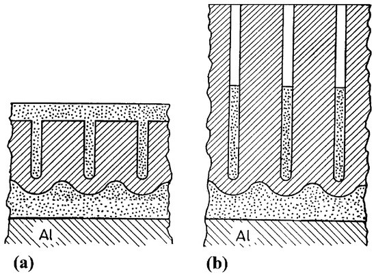
Figure 6. Schematic picture of complex anodic layers: (a) complex film obtained by filling a porous film (b) complex film obtained by filling a porous film with deep pores. Reprinted with permission from [39]; Copyright 2002 Elsevier.
6. Effect of the Electrolyte Temperature
During the process of aluminum anodizing, not only the mass transfer needs to be considered, but also the heat transfer [2]. Heat is produced during anodizing mainly by Joule heating due to ionic current passing through the highly resistive oxide layer on the aluminum electrode [2]. Aerts [2] dealt in his PhD thesis with the role of heat transfer and the role of the electrolyte and electrode (i.e., the aluminum part) temperature during anodizing. The electrolyte temperature has an effect on the oxide morphology, visualized in Figure 7. High electrolyte temperatures lead to pore widening close to the oxide/electrolyte interface [41]. This effect is caused by the higher aggressiveness of the electrolyte at higher temperatures, which accelerates the oxide dissolution reaction. The pore widening effect is gradually reduced towards the alloy/oxide interface [41]. In fact, the pore diameter is found to be proportional to the applied formation voltage and independent of the electrolyte temperature in regions close to the barrier layer [41].
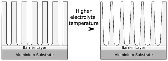
Figure 7. Schematic illustration of the effect on the anodic oxide morphology of increasing the electrolyte temperature.
The electrolyte temperature also has an influence on the microhardness of the film, which decreases with increasing electrolyte temperature [2]. To assess the significance of the electrode temperature, Aerts [2][41] studied anodizing in a cool electrolyte with a high electrode temperature and vice-versa, keeping the difference of temperature electrolyte-electrode constant. According to his findings, the electrode temperature affects the formation ratio of the oxide layer to a larger extent than the electrolyte temperature.
The impact of the electrolyte temperature on the oxide barrier layer thickness is controversial. In the literature claims can be found reporting barrier layer thinning with an increase of the electrolyte temperature [5][19], while others report no significant changes [16][29][42].
This entry is adapted from the peer-reviewed paper 10.3390/coatings10111106
References
- Brace, A.W.; Sheasby, P.G. The Technology of Anodizing Aluminum; Technicopy Limited: Gloucestershire, UK, 1979; ISBN 0-905228-08-1.
- Aerts, T. Study of the Influence of Temperature and Heat Transfer during Anodic Oxide Growth on Aluminum. Ph.D. Thesis, Vrije Universiteit Brussel, Ixelles, Belgium, 2009.
- Thompson, G.E. Porous anodic alumina: Fabrication, characterization and applications. Thin Solid Film. 1997, 297, 192–201.
- Abrahami, S. Cr(VI)-Free Pre-Treatments for Adhesive Bonding of Aerospace Aluminum Alloys. Ph.D. Thesis, Delft University of Technology, Delft, The Netherlands, 2016.
- Sulka, G.D. Highly Ordered Anodic Porous Alumina Formation by Self-Organized Anodizing. In Nanostructured Materials in Electrochemistry; John Wiley & Sons, Ltd.: Hoboken, NJ, USA, 2008; pp. 1-116. ISBN 978-3-527-62150-7.
- Xu, Y.; Thompson, G.E.; Wood, G.C.; Bethune, B. Anion incorporation and migration during barrier film formation on aluminum. Corros. Sci. 1987, 27, 83–102.
- Garcia Rubio, M. Optimisation of a Non-Chromium Containing Tartaric Acid/Sulfuric Acid Anodising Bath for Aluminum Alloy for Aerospace Industry Application. Ph.D. Thesis, Universidad Auntonoma de Madrid, Madrid, Spain, 2009.
- De Miera, M.S.; Curioni, M.; Skeldon, P.; Thompson, G.E. The behavior of second phase particles during anodizing of aluminum alloys. Corros. Sci. 2010, 52, 2489–2497
- De Miera, M.S.; Curioni, M.; Skeldon, P.; Thompson, G.E. Modelling the anodizing behavior of aluminum alloys in sulfuric acid through alloy analogues. Corros. Sci. 2008, 50, 3410–3415.
- Curioni, M.; Saenz de Miera, M.; Skeldon, P.; Thompson, G.E.; Ferguson, J. Macroscopic and Local Filming Behavior of AA2024 T3 Aluminum Alloy during Anodizing in Sulfuric Acid Electrolyte. J. Electrochem. Soc. 2008, 155, C387–C395
- Torrescano-Alvarez, J.M.; Curioni, M.; Skeldon, P. Effects of oxygen evolution on the voltage and film morphology during galvanostatic anodizing of AA 2024-T3 aluminum alloy in sulfuric acid at -2 and 24 °C. Electrochim. Acta 2018, 275, 172–181.
- Thompson, G.E.;Wood, G.C. 5-Anodic Films on Aluminum. In Treatise on Materials Science and Technology; Scully, J.C., Ed.; Elsevier: Amsterdam, The Netherlands, 1983; Volume 23, pp. 205–329. ISBN 0161-9160.
- Ono, S.; Ichinose, H.; Kawaguchi, T.; Masuko, N. The observation of anodic oxide films on aluminum by high resolution electron microscopy. Corros. Sci. 1990, 31, 249–254
- Palibroda, E.; Marginean, P. Considerations on the adsorbed water concentration of sulfuric porous aluminum oxide. Thin Solid Film. 1994, 240, 73–75.
- Wernick, S.; Pinner, R. Surface Treatment and Finishing of Aluminum and Its Alloys, 4th ed.; Robert Draper Ltd.: Sevenoaks, UK, 1972; Volume I.
- Voon, C.H.; Derman, M.N.; Hashim, U.; Ahmad, K.R.; Foo, K.L. Effect of Temperature of Oxalic Acid on the Fabrication of Porous Anodic Alumina from Al-Mn Alloys. J. Nanomater. 2013, 2013, 167047.
- Lee,W.; Park, S.-J. Porous Anodic Aluminum Oxide: Anodization and Templated Synthesis of Functional Nanostructures. Chem. Rev. 2014, 114, 7487–7556.
- Takahashi, H.; Nagayama, M. The determination of the porosity of anodic oxide films on aluminum by the pore-filling method. Corros. Sci. 1978, 18, 911–925
- O’Sullivan, J.P.; Wood, G.C. The morphology and mechanism of formation of porous anodic films on aluminum. Proc. R. Soc. London. A. Math. Phys. Sci. 1970, 317, 511–543
- Oh, J.; Thompson, C.V. The role of electric field in pore formation during aluminum anodization. Electrochim. Acta 2011, 56, 4044–4051.
- Garcia-Vergara, S.J.; Skeldon, P.; Thompson, G.E.; Hashimoto, T.; Habazaki, H. Compositional Evidence for Flow in Anodic Films on Aluminum under High Electric Fields. J. Electrochem. Soc. 2007, 154, C540–C545.
- Garcia-Vergara, S.J.; Skeldon, P.; Thompson, G.E.; Habazaki, H. Stress generated porosity in anodic alumina formed in sulfuric acid electrolyte. Corros. Sci. 2007, 49, 3772–3782.
- Skeldon, P.; Thompson, G.E.; Garcia-Vergara, S.J.; Iglesias-Rubianes, L.; Blanco-Pinzon, C.E. A Tracer Study of Porous Anodic Alumina. Electrochem. Solid-State Lett. 2006, 9, B47–B51.
- Sato, N. A theory for breakdown of anodic oxide films on metals. Electrochim. Acta 1971, 16, 1683–1692.
- Nelson, J.; Oriani, R. Stress generation during anodic oxidation of titanium and aluminum. Corros. Sci. 1993, 34, 307–326.
- Bradhurst, D.H.; Llewelyn Leach, J.S. The Mechanical Properties of Thin Anodic Films on Aluminum. J. Electrochem. Soc. 1966, 113, 1245.
- Wüthrich, N. Intrinsic stresses in anodic films on aluminum. Electrochim. Acta 1981, 26, 1617–1623.
- Moon, S.-M.; Pyun, S.-I. The mechanism of stress generation during the growth of anodic oxide films on pure aluminum in acidic solutions. Electrochim. Acta 1998, 43, 3117–3126.
- Sacco, L.; Florea, I.; Cojocaru, C.-S. Fabrication of porous anodic alumina (PAA) templates with straight pores and with hierarchical structures through exponential voltage decrease technique. Surf. Coat. Technol. 2019, 364, 248–255.
- Curioni, M.; Skeldon, P.; Thompson, G.E.; Ferguson, J. Graded Anodic Film Morphologies for Sustainable Exploitation of Aluminum Alloys in Aerospace. Adv. Mater. Res. 2008, 38, 48–55.
- Van Put, M.A.; Abrahami, S.T.; Elisseeva, O.; de Kok, J.M.M.; Mol, J.M.C.; Terryn, H. Potentiodynamic anodizing of aluminum alloys in Cr(VI)-free electrolytes. Surf. Interface Anal. 2016, 48, 946–952.
- Iglesias-Rubianes, L.; Garcia-Vergara, S.J.; Skeldon, P.; Thompson, G.E.; Ferguson, J.; Beneke, M. Cyclic oxidation processes during anodizing of Al–Cu alloys. Electrochim. Acta 2007, 52, 7148–7157.
- Ono, S.; Saito, M.; Asoh, H. Self-ordering of anodic porous alumina induced by local current concentration: Burning. Electrochem. Solid-State Lett. 2004, 7, B21–B24.
- De Graeve, I.; Terryn, H.; Thompson, G.E. Influence of local heat development on film thickness for anodizing aluminum in sulfuric acid. J. Electrochem. Soc. 2003, 150, B158.
- Tu, G.; Chen, I.; Shimizu, K. The temperature rise and burning for high rate anodizing of aluminum in oxalic acid. J. Jpn. Inst. Light Met. 1990, 40, 382–389.
- Chung, C.K.; Liao, M.W.; Chang, H.C.; Lee, C.T. E ects of temperature and voltage mode on nanoporous anodic aluminum oxide films by one-step anodization. Thin Solid Film. 2011, 520, 1554–1558.
- Graeve, I.D.; Terryn, H.; Thompson, G.E. AC-anodising of aluminum: Contribution to electrical and effciency study. Electrochim. Acta 2006, 52, 1127–1134.
- Ashcroft, I.; Cartwright, T.; Bahrani, D.; Critchlow, G. Anodising aluminum alloy. U.S. Patent 7922889B2, 12 April 2011.
- Girginov, A.A.; Zahariev, A.S.; Machkova, M.S. Kinetics of formation of complex anodic oxide films on aluminum. Mater. Chem. Phys. 2002, 76, 274–278.
- Li, D.; Jiang, C.; Ren, X.; Long, M.; Jiang, J. Fabrication of porous anodic alumina membranes with ultrathick barrier layer. Mater. Lett.-Mater Lett 2008, 62, 3228–3231.
- Aerts, T.; Jorcin, J.-B.; De Graeve, I.; Terryn, H. Comparison between the influence of applied electrode and electrolyte temperatures on porous anodizing of aluminum. Electrochim. Acta 2010, 55, 3957–3965.
- Abd-Elnaiem, A.M.; Gaber, A. Parametric study on the anodization of pure aluminum thin film used in fabricating nano-pores template. Int. J. Electrochem. Sci 2013, 8, 9741–9751.