1. Waste Heat Recovery Technologies
As it is known, modern ICE are characterized by an overall efficiency of 40%, so most of the energy generated by them is dissipated, mainly through exhaust gases in the exhaust system and in the cooling system. As you may know, about one-third of the energy contained in the fuel burned in a light diesel engine is expelled with the exhaust gases through the exhaust system
[1][2]. For this reason, numerous studies are being carried out to recover part of the thermal losses in the exhaust system and convert them into electrical energy stored in the vehicle’s battery. The most important thing, however, is the assessment of the heat source because the nature of the exhaust flow changes during the engine operation
[3]. According to Wang et al.
[4], significant energy savings can be achieved by proper recovery of waste heat from ICE. Among the various waste heat recovery technologies in vehicles, the TEG has attracted much attention among researchers around the world
[3][5][6][7][8][9][10]. Its high reliability is due to its compact design (without any moving parts), and the ability to convert heat directly into electricity is another noted advantage.
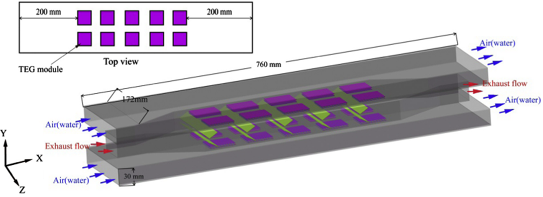
The diagram of the exhaust system in the ETEG thermoelectric generator is shown in
Figure 1. This system includes TEG modules and channels of the heat source and heat sink through which the engine exhaust gases flow. Twenty TEG modules (10 on each side) were installed on both sides of the engine exhaust system
[5]. The exhaust channel system serves as the heat source, and the air flows through the cooling channel (upper and lower exhaust channel) as a heat sink. The presented TEG module consists of a total of 160 TEG units, electrically connected in series and thermally in parallel.
Figure 1. An example of a thermoelectric generator system for energy recovery from ICE exhaust
[5].
Stobart et al.
[11] investigated an ATEG with 16 TEMs in a square arrangement (4 columns each containing 4 TEMs; here, the term column refers to the position perpendicular to the direction of the engine exhaust pipe), achieving a maximum power output of over 30 W. The following dimensions were selected for the modeled TEMs: 65 × 65 × 4 mm
3, to mimic commercially available HZ14
®TEMs (supplied by Hi-Z Technology)
[11]. This study also used computational fluid dynamics (CFD) calculations to predict in detail the impact of design parameter choices. In addition, the study aimed at validating the CFD calculations using a mathematical model to accurately predict the TEG power output. Heat transfer and pressure drop studies for six structures of internal heat exchangers in a passenger car with a 1.2 dm
3 petrol engine using CFD modeling were also carried out by Bai et al.
[12]. It has been shown that the serial plate structure provides the greatest heat transfer and the greatest pressure drop, and that there is a compromise between these parameters. In turn, Su et al.
[13] analyzed three internal structures of heat exchangers for TEGs based on car exhaust: fishbone, pleated and diffuse. Studies have proven that the accordion-shaped design provides better uniform temperature distribution in the system. Unfortunately, both of these studies do not present specific values of electric and net power. In another study, Liu et al.
[14] conducted an analysis of the temperature distribution in a heat exchanger mounted in the exhaust system of a naturally aspirated spark ignition engine with a capacity of 2.0 dm
3. In this study, two systems of internal heat exchangers with different geometries were compared, the first in the shape of a fishbone and the second with a chaotic structure. The authors concluded that a heat exchanger with a chaotic structure achieves better results (maximum electrical power of about 180 W).
The transmission of energy from the engine exhaust of two types of vehicles, a 3.5-ton van and a heavy 40-ton vehicle, at constant speed and the World Harmonized Transition Cycle (WHTC) is presented in
[15]. The simulation evaluated the effect of two different designs of heat exchangers, either with flat fins or staggered stripes, on electrical power and net power output. The influence of the height, spacing and length of the fins, as well as the width and length of the heat exchanger and the height of the thermocouple legs were investigated. The analysis was carried out under fixed conditions, assuming typical extra-urban driving speeds, mass flows and exhaust gas and coolant temperatures for both vehicles. In both tested heat exchangers (flat and offset), a compromise is needed to obtain high electrical power and net power simultaneously. With the criteria used, the flat fin exchanger provides better performance than offset ribbons, especially as a result of the pumping force. Analysis of the size of the TEG shows that doubling the length for maximum electrical power is more efficient than doubling the width
[15]. However, doubling the width of the exchanger is more efficient in terms of net power output. It was found that for typical domestic driving conditions, as well as for the heat exchanger and the external dimensions of the TEG found in the parametric test, the efficiency of energy harvesting is low
[15]. Thus, the best energy recovery efficiency recorded is around 2%, with an average thermoelectric material efficiency of around 4.4% for a light vehicle
[15]. Moreover, for a heavy truck, the results of the parametric analysis indicate the achievement of over 800 W of electric power. In this way, this energy can be used to generate the vehicle’s required electrical network. Thus, this can be used in determining the requirement for the electrical network of a given vehicle. The potential profits from the use of TEG modules in a steady state Sports Utility Vehicle (SUV) were analyzed by Karri et al.
[16]. In their research, they generated electricity in the range of 100–450 W, which translated into fuel savings of about 2.3%. It is obvious that the best results were noticed in trucks, which produce more exhaust gases, which does not mean that passenger cars are not interesting, especially those used mostly in city traffic.
In a study by Lu et al.
[17], two types of structures related to the improvement of heat exchange from the exhaust gas of a car with a spark-ignition engine were tested. The first type of structure is rectangular staggered tape fins, and the second structure consists of metal foams. It was shown that the electrical power obtained for metal foams was definitely higher (in the range of approx. 130–294 W) than for offset tape ends. Unfortunately, with metallic foams, there is a greater pressure drop, and although the total system output power increases, the resulting net power output is lower.
In the work of Ibrahim et al.
[18] the characteristics of car exhaust heat recovery by TEMs using a rectangular exhaust gas exhaust system were investigated. They found that by placing a porous material inside the flue exhaust system, the conversion efficiency of thermoelectric energy increases the heat exchange from the gas stream flowing in the hot side duct to the surface of the TEM. Kim et al.
[6] used the exhaust system of a six-cylinder diesel engine with turbocharging as a source of heat. The ICE worked in various conditions determined by three different engine speeds (i.e., 1000, 1500 and 2000 rpm). The tests determined the influence of the flue gas flow rate on the TEG output power. Then, based on the analysis of the experiment results, a contour map was developed for the TEG output power, expressed as a function of engine load as well as rotational speed. As a result, the output power of the TEG module was found to increase with engine load or engine speed. Summing up the research, the maximum output power was 119 W at 2000 rpm with BMEP 0.6 MPa, and the maximum energy conversion efficiency was in the range of 0.9–2.8%
[6].
In
[19], the efficiency of waste heat recovery for the TEG module equipped with a porous plate-type carrier (perforated plate) was experimentally tested. The obtained results of experimental studies showed that at the engine speed of 1400 rpm, the maximum power output of 98.3 W was obtained with the lowest insert porosity (0.121), and with the optimal insert porosity (0.416), the maximum energy conversion efficiency was 2.83%
[19]. Increasing the conversion efficiency and the output power of the tested TEG module can be achieved by using a porous internal medium, the values of which are 0.461 and 0.32, respectively. It was ultimately shown that a plate-type porous medium with a porosity greater than 0.32 should not be used in the current configuration of the TEG module because the back pressure in the passenger car exhaust system would exceed the allowable limit of 3 kPa.
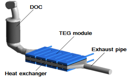
Figure 2 shows an exemplary configuration of the TEG system with a preceding diesel oxidation catalytic converter (DOC).
Figure 2. TEG system with a preceding DOC.
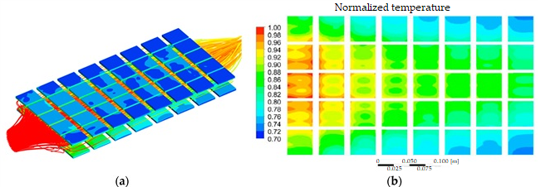
From the CFD simulation, the surface temperature distribution on the hot and cold sides is obtained as shown in
Figure 3. More details on the applied equations and numerical CFD simulations of the model can be found in
[20].
Figure 3. (
a) Simulation of flue gas flow in the TEG module and (
b) temperature distribution in the modules (upper surfaces)
[21].
The scientific literature presents numerous studies devoted to the modeling of thermal waste energy harvesting systems in automotive applications. Meng et al.
[22] developed a multi-physics control-volume TEG model for waste heat recovery from automobile exhaust. In these studies, the constant state of exhaust gas was taken into account, and the thermoelectric material used was Bi
2Te
3. This study analyzed and discussed in detail the number and size of thermocouples used in the system and the direction of flow in the heat exchanger on the cold side. Temperature inequality occurring along the flow direction and its impact on TEG parameters are presented. In the articles by Kumar et al.
[23][24], a numerical model was developed for the TEG corresponding to the conditions found in a light commercial vehicle. Another mathematical model of TEG was presented by Wang et al.
[4]. Their model operates in a steady state and uses the engine exhaust in the vehicle as a heat source. Yu et al.
[25][26] developed a numerical model based on which they found that the performance of the TEGs improved as the driving speed of the pickup vehicle increased. A range of power values of 18–220 W was obtained when the driving speed was increased from 20 km/h to 120 km/h, and the transient behavior of the TEG modules in various driving conditions was tested.
In turn, Ma et al.
[27] tested the performance of a TEG system equipped with plate-fin heat exchangers for the effect of longitudinal vortex generators (LVGs). These tests showed that there is great potential at LVGs to improve the efficiency of TEG modules. The input heat and open-circuit voltage in the TEG module with LVG under basic system operating conditions are increased and range from 41% to 75% compared to the normal smooth TEG channel
[27].
Research in the field of TEG is not only the domain of scientific centers but also of automotive companies, who are working tirelessly on solutions for energy recovery in the vehicles they produce. For example, BMW has strategies for commercializing vehicles with TEG installation and combining TEG and catalytic converter functions to improve system compactness
[28]. They were also involved in the production of highly efficient and environmentally friendly thermoelectric modules. On the other hand, General Motors has developed a TEG with a rectangular configuration, aimed at the Chevrolet Suburban, which includes two different types of TEG modules
[29].
2. Braking Energy Recovery
Parallel to the progress of energy management technology in the propulsion system
[30], work is underway on the recovery of energy from the vehicle braking process
[31][32][33][34][35]. Braking energy in a hybrid vehicle can be recovered and recycled by the regenerative braking system
[36][37][38], which significantly saves energy and reduces the emission of harmful gases into the atmosphere. In the literature, you can find many works that refer to the recovery of energy from the braking force. Most of the studies, however, refer to EV
[34][36][39][40] or hybrid vehicles
[41][42][43], and only a few refer to those powered by an ICE
[33][44] and other machines
[45]. The reason for this may be achieving significantly lower benefits compared to hybrid or EV. According to Held et al., test cycle simulations with a variable speed profile show that 7% of energy can be saved without increasing travel time or deviating from the normal driving pattern
[44].
Thanks to the use of the regenerative braking system, it is possible to use the engine to convert the kinetic energy of braking into electric energy and store it in the vehicle’s battery. The electric energy obtained in this way can then be used for further driving. In this case, we obtain a more efficient use of electricity, which translates into a greater range of the vehicle. For these reasons, it was important to maximize the recovery of braking energy under safe braking conditions and was the main goal of research on energy flow management in hybrid and electric vehicles.
The regenerative braking strategy for rear-wheel drive EV proposed by Zhang et al.
[46] improves the efficiency of regenerative braking up to approx. 47%. In the experiment of Qiu et al., this model was experimentally verified, and the obtained results confirmed the effectiveness of this strategy for a constant input of 58.56% and for a dynamic action of over 69%
[47]. In turn, Itani et al. compared flywheels with supercapacitors as the second source of energy for EV driven by the front axle
[48]. Their results showed the superiority of ultra-capacitors in terms of mass, specific energy and specific power. Reusing braking energy was more convenient and safer for the batteries during regenerative braking
[48].
Lu et al.
[49] presented research on a strategy for controlling the regenerative braking of a fully electric composite energy bus based on the use of engine performance. In this study, they achieved a relative increase in braking energy recovery of nearly 48%. Research results conducted by Chu et al.
[50] show that based on the World Light Vehicle Test Cycle (WLTC), the energy recovery rate can reach 30.4%, while ensuring braking safety even when braking with high intensity. Similar values for the WLTC test were obtained by Sandrini et al.
[51], where the energy saved was 29.5 to 30.3 percent. In this study, the braking energy recovery logic was tested using a simulation on a front-, rear- and all-wheel drive compact car.
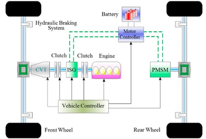
In the research presented by Yang et al.
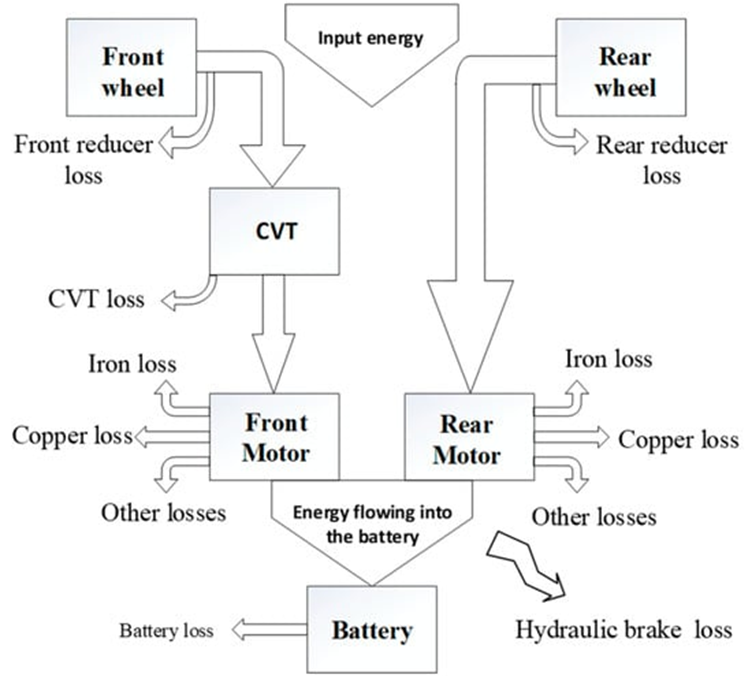
[34], a hybrid electric vehicle system was used, the schematic diagram of which is shown in
Figure 4. When high power demand is required, both motors can work simultaneously. Both axles of the vehicle are equipped with electric motors, which ensures good dynamics in purely electric mode, and it is also possible to obtain more energy during braking.
Figure 4. Schematic diagram of dual motor hybrid electric vehicle
[34]. CVT—continuously variable transmission; PMSM—permanent magnet synchronous motor; ISG—integrated starter generator.
The vehicle controller is responsible for collecting data on vehicle speed, brake pedal position and master cylinder pressure, among others. After detecting the signal from the brake pedal, the driving status of the vehicle is quickly determined; then, the control signal via the Controller Area Network (CAN) bus is sent to the downstream controller
[34]. The downstream controller, on the other hand, identifies the correlation according to the control signal, after which it sends signals to the hydraulic control unit and the motor control unit according to a predetermined algorithm to execute the control instructions from the driver.
Figure 5 shows the graph of energy consumption, where the losses of individual system elements in the braking process are marked.
Figure 5. Graph of energy consumption and losses during braking
[34].
As shown in the diagram in Figure 5, energy losses occur in every element of the system, starting from the wheels of the vehicle, through the CVT transmission, to the motors and the energy stored in the battery. Other energy losses not related to the braking process, such as motion resistance or wind resistance, are omitted at this point.
Another braking strategy analysis for a Formula SAE electric race car, for steering the vehicle wheels on the front and rear axles, was presented by Henao-Muñoz et al.
[52]. The proposed braking strategy is aimed at increasing the recovery energy through the appropriate distribution of braking forces between the wheels on both axles of the vehicle. In this study, three braking strategies were compared with regard to braking energy yield and vehicle stability. The results of the simulations show that the proposed management strategy allows for greater energy recovery while avoiding blocking both the rear and front wheels of the vehicle
[52].
Similar studies for a Formula SAE electric racing car were conducted by Dolara et al.
[53]. All components of the EV and hybrid lithium–ion batteries as well as ultracapacitors are used to store the kinetic energy of regenerative braking in the Kinetic Energy Recovery System (KERS)
[53]. Their results show the ability of the converter to operate in resonant mode in both boost and step down modes. The noted disadvantage of this solution is the presence of high current peaks in the resonant coil. On the other hand, the use of more than one interlaced converter and the adoption of an appropriate efficiency factor enable the correct operation of this system.
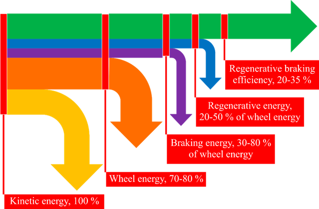
Summing up the considerations on the distribution of energy recovered during braking, the following graph of energy distribution in an EV can be generated (Figure 6).
Figure 6. Energy distribution in EVs
[54].
Analyzing the graph in
Figure 6, it can be concluded that braking can absorb from 30% to 80% of the vehicle’s kinetic energy. This share depends on energy management and the implementation of the braking process. Due to the increased range, extended mileage and increased efficiency of electric vehicles, it is so important to properly manage and recover energy. In addition to the overall improvement of the vehicle’s efficiency, regeneration can significantly extend the service life of the braking system, because in such operating conditions, the mechanical parts of the system wear much more slowly
[54].
3. Energy Harvesting from Vehicle Suspension
Regardless of the drive that a motor vehicle is equipped with, each has a suspension system whose task is to dampen vibrations from the ground in order to ensure adequate vehicle stability, safety and comfort of passengers. That is why this vehicle system can also be used to obtain additional energy, which under normal conditions (without recovery devices) is damped in the suspension and consequently lost. Due to the fact that only 12–30% of the energy contained in the fuel is used to propel the vehicle in order to overcome the friction of the road surface and air resistance
[55], and one of the main losses is the dissipation of vibrations in the suspension (shock absorber)
[56], such an important issue is the technology of obtaining energy from the vibrations of the vehicle suspension system
[57][58].
As shown in study
[59], for a medium-sized vehicle moving at a speed of 96.5 km/h, the average power obtained from the suspension system is in the range of 100–400 W, on B- and C-class roads. As presented by Zhang et al.
[60], based on the tests carried out by Audi AG, it is possible to recover energy with an average power of approx. 150 W from the energy harvesting system. Large differences in the presented values of the obtained power occur due to the type of the test section of the road on which the vehicles were moving. Thus, for a passenger car moving on a new section of the German motorway, it is only 3 W, while on an uneven national road, the energy efficiency obtained from the system was even 613 W. In turn, Li et al.
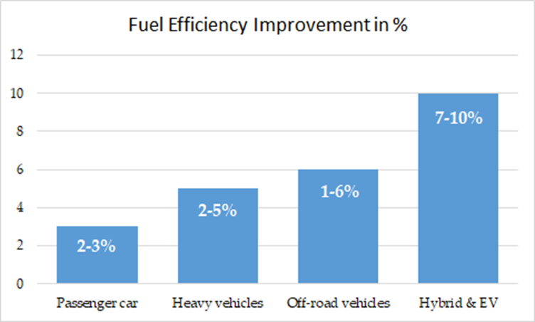
[56], show that with optimal load resistance (at 7.5 Ω) and harmonic excitation with an amplitude of 8 mm and a frequency of 2 Hz, a maximum of 248.8 W of instantaneous power can be obtained with an average of 114.1 W and a maximum of 38.81% efficiency of energy obtained from the vehicle suspension system. In cars, collecting dissipated kinetic energy during damping can save fuel by about 2–10% of the car’s total fuel consumption
[61].
Figure 7 shows the possibilities of fuel savings due to the use of systems for obtaining kinetic energy during damping for various types of vehicle.
Figure 7. Fuel savings for different types of vehicles using energy harvesting systems.
Analyzing the data presented in Figure 8, it can be concluded that off-road vehicles and trucks as well as overloaded vehicles show a greater potential for fuel savings (up to 6%) compared to passenger cars, which give only a half of this result, and that is up to 3% fuel savings. However, as shown in Figure 8, the best results can be obtained with electric and hybrid vehicles. This is due to the differences in vibration intensity levels for individual vehicles. For this reason, energy harvesting systems from the suspension system should be of interest primarily to fleet customers.
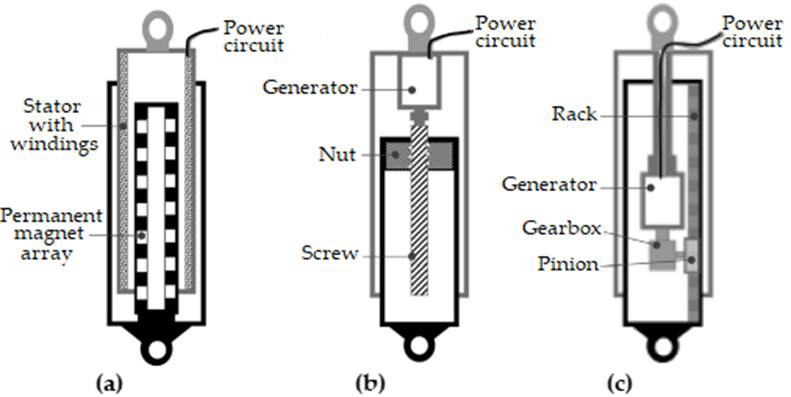
The key element that converts the mechanical energy of vibrations into electrical energy in the suspension system is a special energy shock absorber. It mainly includes two elements: the energy conversion unit (linear or rotary electric motor) as well as the transmission devices (from reciprocating to rotary motion)
[62]. Therefore, vibration energy flows into the vehicle’s suspension system, causing the shock absorber piston rod to move vertically up and down sequentially. Electricity could be generated from these perpendicular oscillations in two ways: directly by the linear electromagnetic harvesters or indirectly by the rotary electromagnetic harvesters
[63]. Schematics of various electromagnetic regenerative shock absorbers used in the vehicle suspension system are shown in
Figure 9.
Figure 9. The electromagnetic regenerative shock absorbers (a) linear motor, (b) ball screw and (c) rack-pinion.
Zhang et al.
[60], used an electro-hydraulic shock absorber to collect energy in off-road vehicles, thanks to which they obtained an average regenerative power of 110.6 W. They also showed that a trade-off is necessary between energy harvesting characteristics and shock damping. Li et al.
[56] showed the construction of energy-receiving shock absorber receiving energy and the optimization of the control system, according to the diagram shown in
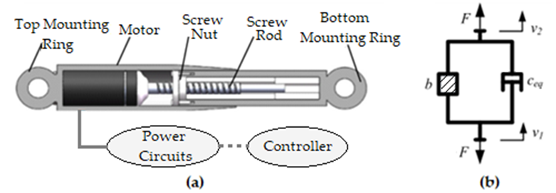
Figure 10a. The construction of the shock absorber consists mainly of two elements—the motor and the ball screw. The task of the ball screw is to transform the vibrations that are generated between the vehicle body and the chassis into the rotation of the motor. The electric motor mounted in the shock absorber acts as a power generator that converts the kinetic energy of the suspension system into electricity, which is stored in the battery for further use, while ensuring the damping force
[56] and proper vehicle stability.
Figure 10. Structural diagram of the ball screw of the shock absorber—(a) and equivalent to the dynamic model—(b).
Since the system is affected by the moment of inertia of the motor rotor and the screw rod, the shock absorber for energy harvesting can be treated as a conventional oil shock absorber connected in parallel with an inerter, as shown in
Figure 10b
[62]. The individual symbols marked in the figure mean the following:
F is the total shock absorber force;
v1 and
v2 are vehicle body and chassis velocities, respectively;
b is inertia value; and
ceq is the equivalent damping coefficient. The PMSM generator (synchronous motor with permanent magnets) and the buck-boost converter, which is used to collect electricity, bring positive effects. Based on the test results, it can be said that the proposed control system and control strategy were characterized by a high response speed (i.e., 4 Hz) and a small tracking error, which amounted to 6.44%, compared to the set value of the damping coefficient
[56]. It was found that this is a good basis for further research on the energy-harvesting semi-active suspension system
[56]. In addition, the tests showed a high efficiency of energy collection from the tested suspension, ranging from 40.72% to 70.55% with sinusoidal excitation and random road excitation.
In the studies presented in
[63], it was shown that vehicle vibrations caused by road irregularities can produce an average power of 350 W for a medium-sized passenger car (equipped with four energy-harvesting shock absorbers). However, for larger vehicles, harvesting power can be significantly higher than that of a sedan vehicle. The regenerative electromagnetic shock absorber has a relatively small load capacity, so it is more suitable for passenger cars, minivans, etc. An electro-hydraulic shock absorber can provide more damping force that is typically required in off-road vehicles. Therefore, it can be concluded that there is a large potential for recovering energy dissipated from the vehicle suspension system, which can be used to power, among others, comfort-enhancing systems. More detailed information on the collection of dissipated energy from the vehicle suspension system and the design of systems for energy harvesting can be found in the available scientific literature
[56][59][61][64].
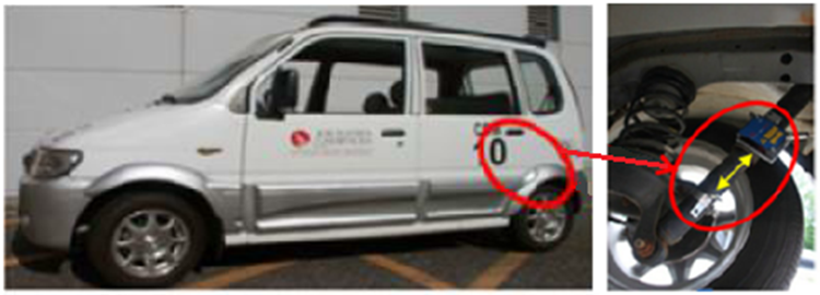
Figure 11 shows an example of the position of the shock absorber equipped with the energy harvesting system on the rear axle of the minivan vehicle.
Figure 11. Location of the shock absorber to collect energy in the minivan vehicle
[59].
According to Al-Yafeai et al.
[65], for passenger cars moving at a low speed of about 47 km/h, about 200 W of power dissipated in the suspension shock absorbers was recorded. Other studies presented above also confirm the high potential of generating energy in the vehicle suspension system. The energy yield increases depending on the type of vehicle (passenger car, van, truck) and the type of surface on which it moves. Therefore, this amount of energy cannot be ignored and is worthy of interest as well as harvested from the system.
As the presented literature research has shown, the energy yield from the vehicle suspension system, depending on the type of vehicle and the harvester used, is quite diverse. The ranges of recovered power range from several dozen watts to over 600 W, but, on average, it is up to about 300 W for a medium-sized passenger car. This energy can be used to power various electrical systems in the vehicle, such as comfort devices.
This entry is adapted from the peer-reviewed paper 10.3390/en16093787