Your browser does not fully support modern features. Please upgrade for a smoother experience.
Please note this is a comparison between Version 1 by YiPing Han and Version 2 by Jason Zhu.
Structural health monitoring is currently a crucial measure for the analysis of structural safety. As a structural asset management approach, it can provide a cost-effective measure and has been used successfully in a variety of structures. TIn recent years, the development of fiber optic sensing technology and vision sensing technology has led to further advances in structural health monitoring.
- fiber optic sensing technology
- vision sensing technology
- integration
- structural health monitoring
- SHM
1. Introduction
The rapid development of various industries in today’s society has caused the composition, form, and function of many structures to become increasingly complex [1]. Especially since the 1990s, there has been an increasing emphasis on monitoring the quality and longevity of modern structures, due to the implementation of engineering projects such as large concrete buildings, large steel structures, and geotechnical structures. Long-term exposure to complex working conditions will inevitably result in varying degrees of damage and defects in these structures [2]. These potential damages and defects will make a structure much less stable and safe, thus increasing the likelihood of catastrophic accidents.
If these damages and defects are not foreseen and monitored in a timely manner, they can not only cause significant property damage but also pose a great threat to personal safety. Therefore, there is a great need for real-time health monitoring and assessment of structures to improve their safety performance. Structural health monitoring (SHM) is a technology that can meet this need very well, and it has become a popular topic of research in the engineering and scientific community worldwide [3][4][3,4].
The concept of SHM was first proposed and researched within the field of aviation [5], and it is based on the idea of mimicking the human nervous system [6]. The SHM system consists of sensors, data acquisition and transmission systems, structural warning and assessment systems, and data management systems [7]. It uses sensors integrated into the structure to obtain information related to the health of the structure, such as strain and temperature, in real-time. It then uses a transmission system to store this information in a data management system. Finally, it processes this information using a structural warning and assessment system to obtain the health status of the structure. Thus, the sensors are the crucial tools by which the SHM system obtains information, and are considered the sensory organs of the SHM system [8]. Therefore, the implementation of SHM systems relies heavily on the support of sensing technology.
5. Basics and Principles of Vision Sensing Technology
Computer vision, a simulation of biological vision using computers and related devices, is an important part of the field of artificial intelligence (AI) [9][197]. The goal of its research is to provide computers with the ability to perceive three-dimensional (3D) environmental information through two-dimensional (2D) images [10][198]. In recent years, with the development of digital camera technology and computer processing ability, various applications of computer vision technology have become possible [11][199]. One of the applications is the use of a vision sensor system for SHM [12][25]. The vision sensor system is an SHM system for the long-range, non-contact, non-damage monitoring of structures [9][197]. It is composed of cameras and vision sensors as the main components, with computer image recognition and tracking algorithms as the core. The components of the vision sensing system and the relationship between them are shown in Figure 1. A vision sensor is an instrument that uses optical elements and imaging devices to obtain image information about the external environment. The vision sensor is the direct source of information for the entire vision sensor system. It consists mainly of one or two image sensors, sometimes with light projectors and other auxiliary equipment. The primary function of the vision sensor is to acquire enough of the raw images to be processed by the system. Image sensors can use laser scanners, Charge Coupled Devices (CCD), or Complementary Metal-Oxide-Semiconductors (CMOS), etc.
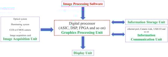
Figure 1. The components of the vision sensing system and the relationship between them.
The main principle of vision sensor technology is image processing, where the image captured by the camera is processed to calculate the characteristic quantities of the object (area, the center of gravity, length, position, etc.) and output the data and judgment results [13][200]. Vision sensors can capture light from an entire image with thousands of pixels. The clarity and detail of an image are usually described in terms of resolution, expressed in terms of the number of pixels. After capturing an image, the vision sensor compares it to a baseline image stored in memory to perform an analysis. This can be used to directly identify fractures or spalling [14][15][201,202].
As an important component of visual sensing technology, digital image correlation (DIC) has been widely used in structural health monitoring (SHM) [16][203]. DIC is an optical measurement method that can obtain information about the deformation field (such as displacement field, strain field, etc.) on the surface of an object. It needs to perform certain correlation operations on the two speckle patterns of the object surface taken before and after the deformation. It was first proposed by Yamaguchi et al. in 1981 [17][204]. These researchers measured the in-plane displacement of the object by creating stripes on the surface of the object and using a laser speckle in combination with a linear sensor. However, the accuracy of the test results was low because of the non-linear experimental process. Later, Peters and Ranson [18][205] proposed to divide the deformation field into different size analysis regions (i.e., subsets), and performed correlation calculations on the subsets before and after the deformation. This was also early two-dimensional digital image correlation technology (2D DIC). However, 2D DIC can only measure the in-plane displacement of the object, and cannot accurately calculate the off-plane displacement. To overcome this limitation, Luo, Chao, et al. [19][206] combined the concept of binocular stereo vision with the 2D DIC technique and proposed a three-dimensional digital image correlation measurement method (3D DIC). It captures information about the object by using two cameras at the same time to build a three-dimensional model of the object, and can analyze the three-dimensional image of the object.
3. Progress of Vision Sensing Technology
Speckle patterns are an important feature of the DIC technique, and their quality has a significant impact on measurement accuracy. Therefore, the progress of DIC technology is inseparable from the optimization of speckle patterns [20][21][209,210]. In addition, some of the advances in DIC technology are focused on the number of cameras. For example, with the addition of additional optical elements, 3D deformation measurement of structures can be achieved with a single camera [22][211]. This technique negates the need for two precisely synchronized cameras and significantly minimizes hardware costs. Other studies have expanded the measurement range and improved measurement accuracy by increasing the number of cameras [23][24][212,213]. In addition, camera calibration is critical in the implementation of DIC technology, and there is a well-established and widely accepted standardized technique [25][214]. Of course, new calibration methods are constantly proposed to accommodate more complex application scenarios [26][27][215,216].
In addition to advances in analysis methods and operations, advances in software algorithms have contributed to making DIC technology a robust and mature technology. There have been many reviews summarizing the progress of DIC algorithms, and the next section, focuses on summarizing the many vision-based algorithms proposed in recent years. It includes edge detectors [28][217], thresholding [29][218], segmentation [30][219], and filter-based algorithms [31][220]. Especially when using modern algorithms that implement higher-order interpolation filters, the bias caused by the image-matching algorithm is very low, even for very poor speckle quality [32][221]. In addition, Yang et al. [33][222] applied the discrete cosine transform and wavelet transform techniques to the DIC algorithm to obtain accurate displacement and strain fields by using only 5% of the original image size. With the advancement of computer computing power, in addition to DIC-related algorithms based on global finite elements [34][223], methods based on machine learning and artificial intelligence have emerged [35][36][224,225]. Among the emerging machine learning algorithms for signal processing, convolutional neural networks (CNN) for local damage assessment and anomaly detection of structures have become a notable trend [37][226]. However, many machine learning algorithms work well only under a common assumption that the training and test data have the same distribution and feature space [38][227]. This assumption is obviously difficult to satisfied considering the practical applications, especially in the execution of SHM. To solve this problem, transfer learning (TL) has been taken as a promising approach [39][228]. Of course, the latest development of the digital twin (DT) offers another new option for better implementation of SHM [40][229]. In conclusion, the continuous improvement and development of the DIC algorithm makes DIC matching faster and more accurate, while the integration with some popular algorithms makes it more advanced and intelligent.
4. SHM Applications of Vision Sensing Technology
4.1. Laboratory Investigations
The development of various technologies continues to drive the advancement of DIC technology. Experiments related to the use of DIC technology for measuring strain and displacement of structures have been increasing and have matured. For instance, the 2D DIC method was used in the laboratory by Hoult et al. [41][230] to measure strains in steel specimens under uniaxial loading; the results were compared with those of strain gauges and the two were in high agreement. In the experiments of Ellenberg et al. [42][231], the 3D DIC method was used to measure the static displacements of specimens in the laboratory with sub-pixel accuracy. In addition to measuring strain and displacement of specimens, vision sensing techniques are more often used to probe crack development in the laboratory. One of the most typical tests is the measurement of crack width and crack slip in reinforced concrete (RC) structures using the DIC technique [43][232].
In addition to RC structures, Hallee et al. [14][201] tested their ability to capture cracks in masonry structures by training CNN. The results show that the CNN architecture suitable for concrete crack detection is not applicable to the detection of cracks in masonry structures. The latest experimental investigation of using DIC technology for SHM is mainly to investigate the reliability of new sensing technologies, such as fiber optic sensing technology. There are also studies to demonstrate the advantages and development potential of combining DIC and other sensing technologies.
In addition to the normal test environment, DIC technology has attracted many scholars to use it in the field of high-temperature measurements and to conduct in-depth research. Since Turner and Russell first discussed the limitations and development potential of the DIC method for high-temperature applications in 1990 [44][233], high-temperature DIC research with increasing upper-temperature limits has been conducted. In recent years, Liang et al. [45][234] used in situ scanning electron microscopy (SEM) to measure the high-temperature deformation and fatigue properties of nickel-based single crystal high-temperature alloys up to 800 °C. In 2020, Pan et al. [46][235] applied DIC to the ultra-high temperature field (over 3000 °C) using an electron beam heating technique and successfully performed full-field thermal strain measurements on tungsten specimens. In the same year, Chen et al. [47][236] used a single polarization camera and a polarizing beam splitter to synchronously capture two full-frame sub-images with orthogonal polarization directions. They built a single-camera stereo polarization DIC system and validated the effectiveness and accuracy of the proposed technique through high-temperature testing. Similarly, Wang et al. [48][237] proposed a full-field thermal deformation measurement method based on high-temperature DIC using a polarization camera as the image acquisition system in combination with the optical filtering system. Finally, they used the built system to perform thermal deformation tests on ceramic materials. The results show that the system can achieve high contrast and clear image acquisition under high-temperature conditions. The fundamentals of high-temperature DIC and some of the challenges it faces are described in detail in a recent review; interested readers can read the reference [49][238] for further information.
4.2. Field Applications
With the development of DIC technology and its wide application in the laboratory, its advantages are becoming more and more obvious. It not only has the advantages of non-contact, simple operation, full-field measurement, a wide range of use, and high measurement accuracy, but also has very low requirements for the device [50][239]. Therefore, DIC technology has been widely used in engineering projects to monitor the health of structures. McCormick and Lord used the 2D DIC method to measure the vertical displacements of a highway bridge deck with four 32-ton trucks loaded statically [51][240]. Yoneyama et al. [52][241] used the 2D DIC method to estimate the deflection of the main beam of a bridge carrying a 20-ton truck. Aiming also to measure bridge deflection, Winkler et al. [53][242] monitored and evaluated the Warton bridge with a three-car train operating on it using DIC. Recently, to obtain full-field deflection measurements of bridges more easily, Tian et al. [54][243] proposed a new method based on off-axis DIC, which uses a “straight-line fitting scheme” to measure the full-field deflection over multiple points. This measurement is consistent with the data obtained with conventional displacement meters. Among the reported factors affecting measurement accuracy are internal factors (e.g., relevant algorithms, mathematical functions, etc.) and external factors (e.g., measurement environment, instrument parameters, and target characteristics). The effectiveness and practicality of the method have been verified by the application of SHM for indoor cantilever girders and high-speed railway concrete bridges. In these field test operations, the DIC is implemented by mounting the target to the bottom of the girders to measure the bridge deflections [55][244]. In addition to measuring bridge deflection, DIC is also used to monitor the development of cracks in reinforced concrete bridges in the field [56][245].
The above-mentioned field applications of DIC technology are generally used for static monitoring of structures. Some researchers have also investigated the use of the DIC technique for the dynamic monitoring of structures accordingly. For example, the combination of DIC technology and UAV technology has been used for the health inspection of structures. For example, Reagan applied the 3D DIC method to the long-term monitoring of bridge deformation using an unmanned aerial vehicle (UAV) carrying a stereo camera [57][246]. Narazaki et al. [58][247] proposed a vision-based autonomous UAV navigation planning method for rapid post-earthquake inspections of reinforced concrete railway bridge viaducts. The results show that the method can achieve centimeter-level accuracy and has great potential for application in post-earthquake structural inspection. Du et al. [59][248] investigated the dynamic response of the stay cable Guanhe bridge by using two measurement techniques, DIC and digital image processing (DIP), in combination with a conventional accelerometer.
Measuring the dynamic response of a structure under excitation, such as displacement and acceleration, and performing modal analysis and system identification to obtain the dynamic characteristics of the structural system is an important element of SHM. Several other vision-based methods have been used for the dynamic monitoring of structures. Feng et al. [60][249] first demonstrated the accuracy of vision sensors in dense full-field displacement measurements by experimenting with a simply supported beam structure in the laboratory. In this experiment, the structure frequency and vibration patterns were obtained from the displacement measurements of 30 measurement points of the structure by one camera. They were in high agreement with the results obtained using six accelerometers. The vision sensor was subsequently applied to remote (camera at approximately 300 m from the bridge’s mid-span location), real-time, and multi-point (3 measurement loci) dynamic displacement measurements of the Manhattan Bridge under the excitation of an operating train.
With the trend of digitalization, Min et al. [61][250] explored the feasibility of real-time dynamic displacement monitoring with smartphones to make computer vision techniques simpler and easier to implement. They developed a new application for the iPhone in the iOS environment to perform vision-based displacement measurements. In an outdoor shaker test, the method achieved sub-millimeter displacement measurement accuracy at a distance of 33 m from the target, and the dynamic displacement measurement results matched well with those of a conventional laser displacement sensor. Subsequently, Kromanis et al. [62][251] demonstrated the capability of smartphone technology to provide accurate information about structural deformation when combined with appropriate image processing software in a laboratory setting. Interested readers are referred to the recent comprehensive review on smartphone-related sensor technologies and their applications in SHM by Malekloo et al. [63][252]. In conclusion, vision sensing technology applied to SHM is developing rapidly and it has been considered a new generation of sensing technology in SHM applications [64][10].
From the above description, it is clear that vision sensing technology has the following main advantages compared to fiber optic sensing technology:
-
High accuracy: the vision sensor system can directly measure the overall displacement of the structure; the overall displacement of the structure more directly reflects the changes in the overall stiffness of the structure, and it has the characteristics of artificial intelligence, so it can reflect the overall state of the structure more accurately. In addition, the test instrument can be placed further away—even up to several hundred meters away—and can also achieve the desired accuracy.
-
High flexibility: through the lens of the camera and computer image processing algorithms, with the use of non-contact vision sensing technology for displacement measurement, it is not necessary to consider the complex method by which to embed the sensor into the structure; vision sensing technology can be in the form of non-contact distribution sensing technology, tracking multiple changing targets over a long distance to obtain synchronized data.
-
Low cost: vision sensing systems do not require a large amount of time for sensor installation, do not require physical contact with the structure, and can be controlled remotely, saving time and equipment costs, especially for bridges. Moreover, no traffic control is required for installation [12][25].
5. Integration with Fiber Optic Sensing Technology
The main feature of fiber optic sensing technology is contact measurement, while vision sensing technology is non-contact measurement. For SHM, it is a multidisciplinary research project. Both contact and non-contact measurements on structures are necessary to obtain a more accurate health status of them. There have been a large number of experimental studies combining these two technologies, in particular DFOS and DIC. This integration will facilitate the mutual verification and validation of the results measured by both techniques. In addition, it allows the integration of external strains measured by vision sensing techniques with internal strains measured by fiber optic sensing techniques, which allows for more comprehensive health information of the structure and more accurate predictions.
In 2021, Berrocal et al. [65][253] combined the DIC technique with fiber optic sensing to investigate the accuracy and reliability of DFOS under monotonic and cyclic loading. They also verified the ability of DFOS to estimate the crack width, where the role of DIC is reflected in obtaining accurate and reliable information about the crack formation and development. The experimental results show that most of the errors in crack location and crack width calculated based on DFOS strain measurements are less than ±3 cm and ±20 µm, respectively, compared to the DIC results. These results are in good agreement with their subsequent studies. In subsequent studies, their main contribution was to demonstrate that robust fiber optic cables with protective cladding, well-suited for field applications, also have good strain measurement performance [66][254]. They have a certain strain attenuation compared to the commonly used thin polyimide-coated distributed fiber optic sensors bonded to steel bars.
Some studies similarly use DIC results as an accurate and reliable check. Sawicki et al. [67][255] evaluated the ability of two fiber optic sensors to monitor strains and discontinuities in Ultra-High-Performance Fiber Reinforced Cementitious composites (UHPFRC) by comparing them with the DIC method and the extensometer method. Experimental results show that the use of the extensometer is limited to the elastic and strain-hardening phases for all phases of the structural response of the substrate. The DIC technique is suitable for detecting and tracking localized fictitious cracks during the cracking phase of a structure, but not for observing the strain changes in the structure during the elastic phase. This is due to the large measurement noise that can exist in the elastic phase. DFOS technology enables precise monitoring of the elastic, strain hardening, and softening stages of UHPFRC.
Similar to the previously described study, to obtain improved accuracy and resolution, Zhang et al. [68][256] applied OFDR to investigate the ability of DFOS to detect concrete cracking and large-strain steel deformation. In the process of their research, they used several types of fiber optic cables. To provide practical guidelines for choosing cables, they established a framework for evaluating cable sensitivity and survivability. Similarly, to check the accuracy of DFOS measurements, they also used DIC results for comparison and analyzed the results of both. To investigate the bond stress and surface slip between concrete and steel rebars in cracked and non-cracked RC tensile members of different sizes, Bado et al. [69][257] performed extensive experiments by applying DOFS to the surface of the steel rebars and measured these parameters. To verify the accuracy of these measurements, they also introduced DIC technology as a profiling validation and troubleshooting tool. The DIC was used to collect surface data of the RC structure, which was checked against the local strain data of the reinforcement measured by DOFS. Finally, they observed a good agreement between these two results. This demonstrates the viability and integration application potential of the DOFS/DIC combination for RC structural testing.
There have been some explorations of the combined application of DOFS and DIC. For example, Bado et al. [70][258] investigated the potential and performance of combined DOFS and DIC techniques for internal and external strain monitoring in RC ties. Their results indicate that the combined use of DOFS and DIC provides researchers with an excellent monitoring system. This system provides a complete picture of the internal strain distribution of the member through continuous interaction and inspection between external and internal strain measurements. The concrete mix they used was formed by mixing water and other materials in a certain ratio, and the FOS were bonded to the steel bars in the setup. The entire structure was deformed by the action of the hydraulic actuator and the camera was set to take pictures at regular intervals. Cantone et al. [71][259] considered that the DIC technique can only collect concrete surface data and cannot directly measure the local strain state of the reinforcement. They obtained high-quality results by attaching Fiber Optical Measurement systems (FOM) to the surface of the rebar. This takes advantage of the fact that the FOM allows high-strain gradients to be observed in the bar along its axis for different locations in the cross-section. They combined these two techniques to test three different types of structural elements to re-investigate the interaction between reinforcing steel and concrete from a new perspective. Finally, they show the implications of such interactions on a series of phenomena associated with brittle failure modes.
Similarly, Mata-Falcón et al. [32][221] explored the application of a combination of distributed fiber optic strain measurements on steel reinforcement and DIC measurements on concrete surfaces. They presented the advantages of combining the two measurement techniques: (i) to mutually validate their results, (ii) to relate the stress distribution in the reinforcement to the concrete kinematics, and by this (iii) to investigate the load distribution in the different element parts overtime on a very intuitive basis. Besides that, their main contribution was to discuss the assessment of measurement uncertainty of DIC and FOS in large-scale structural tests. The experimental results showed that the average fiber strain results agreed very well with the DIC results (deviation of about 50 μm/m), and the crack locations predicted by the two measurement methods matched perfectly. Recently, Saeedifar et al. [72][260] similarly integrated FOS and DIC for SHM of an adhesively bonded bi-material full-scale joint. Their results showed that the measurements obtained by FOS and DIC converged. In addition, they integrated acoustic emission sensing (AE) technology to perform a large number of measurements on structures in the quasi-static tensile test.