Electro-thermal modeling is a process of creating a mathematical model to simulate the electrical and thermal behavior of an electric motor drive system. This modeling technique is used to predict the performance of the motor under different operating conditions and to optimize its design for efficiency and reliability. Electric motor drives are used in a wide range of applications, including industrial machinery, electric vehicles, and renewable energy systems. However, these systems can suffer from decreased efficiency and reliability due to the impact of temperature on their performance. Electro-thermal modeling is used to address these issues by accurately simulating the motor's behavior under different temperature conditions. The modeling process involves using software tools to create a mathematical model that includes the electrical and thermal properties of the motor. This model can then be used to simulate the motor's behavior under different loads and temperatures, allowing engineers to predict the motor's performance and optimize its design. One key advantage of electro-thermal modeling is that it allows engineers to identify potential issues in the motor's design and operation before they occur in the real world. By analyzing the motor's behavior under different conditions, engineers can identify areas where the motor is operating inefficiently or experiencing excessive temperatures. They can then modify the motor's design or operating conditions to improve its efficiency and reliability. Thus, electro-thermal modeling is an essential tool for designing and optimizing electric motor drive systems. By accurately simulating the motor's behavior under different conditions, engineers can create more efficient, reliable, and long-lasting motor systems that meet the needs of various applications.
- Switching Loss
- Conduction Loss
- Foster Network
1. Electro-Thermal Modeling Strategy
The accurate estimation of semiconductor losses and thermal characteristics in power electronics systems is difficult, but important due to the influence on system efficiency and reliability. The dynamic electro-thermal model of a traction inverter is implemented using MATLABTM/Simulink. Conduction losses and switching losses (turn-on losses and turn-off losses) are the two types of power losses caused by a semiconductor device's PWM switching cycle [1],[2][1][2]. Fig. 1 Figure 1 depicts the whole assessment approach. The electrical domain is the switch model of the traction inverter which sends the drain-source voltage (Vds) and current (Ids) to the electro-thermal domain. The detailed loss modeling and temperature estimation model are implemented in electro-thermal domain. The loss modeling of this domain is done using a semiconductor datasheet. The losses and junction temperature estimation methods for a semiconductor device have been described below:
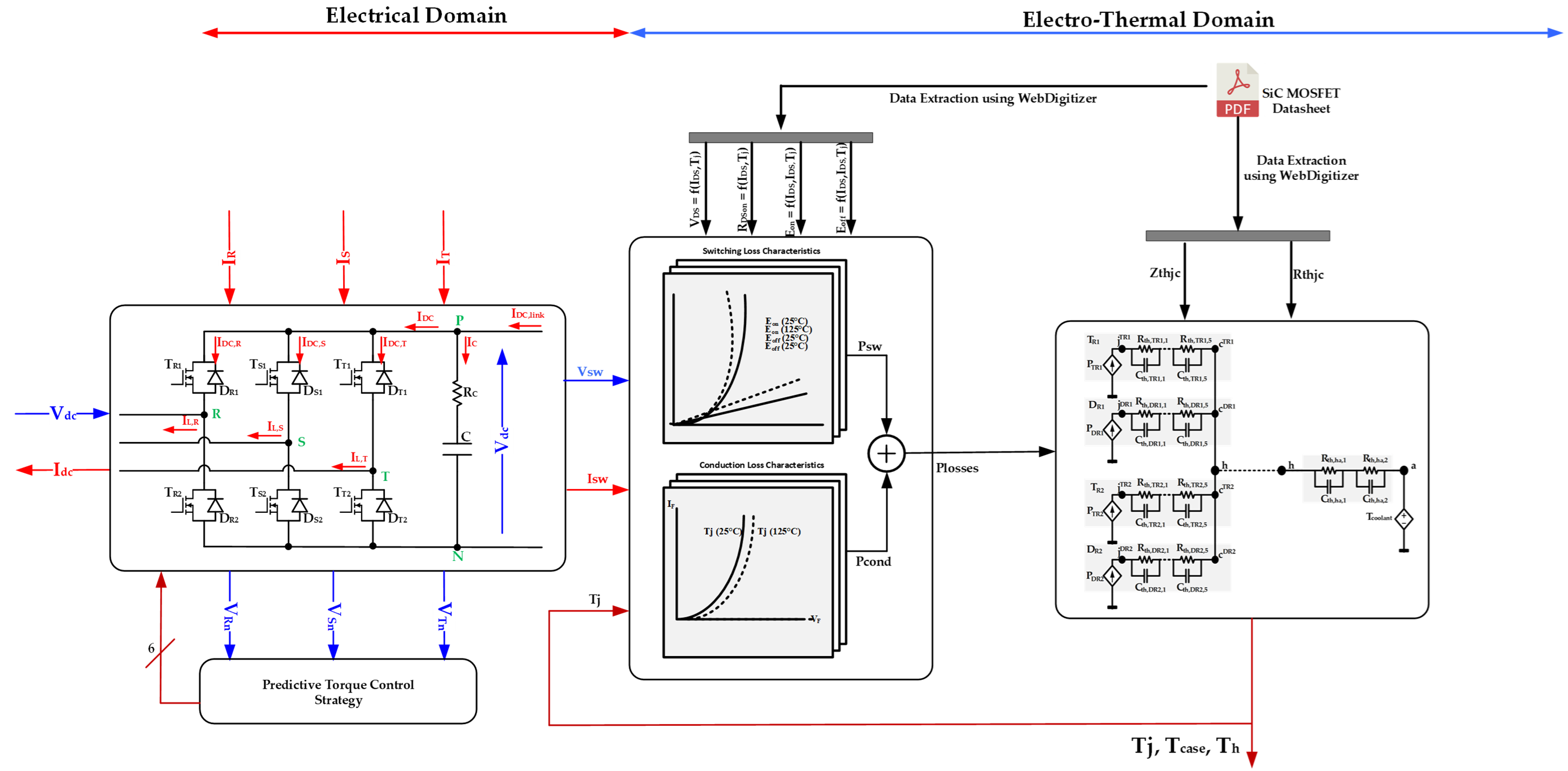
FigFigure 1. 1: The traction inverter electro-thermal assessment procedure with different predictive torque control strategies
A2. Switching Loss Estimation
The industrial semiconductor datasheet values are used to calculate an accurate assessment of switching losses in the device. The datasheet of the Cree SiC module of 1200V, 120A was used in this study. Due to the intricate physics of a switching process, a lookup table [1] technique for estimating switching power losses is more viable and simpler to apply. Lookup tables based on the correlation as shown in Eq. (1) – Eq. (2) are used to estimate switching losses in the device using switching energies found in the datasheet, such as Eswon and Eswoff.
|
(1) |
|
|
(2) |
![]() (1)
(1)
![]()
(2)
where k represents the kth PWM switching pulse index. Hence, the total switching energy is computed by Eq. (3):
|
(3) |
![]() (3)
(3)
The switching power losses can be calculated from the energy losses, using Eq. (4):
![]()
|
(4) |
(4)
where “fsw” is the operating switching frequency. The reverse recovery characteristics now describe the switching losses of a diode. The reverse recovery, on the other hand, may be estimated using Qrr and trr. The switching on loss of a diode is not significant according to the CREE datasheet. As a result, the diode's switching losses are relatively low. We can also estimate the reverse recovery losses of MOSFET in MATLAB/Simulink using Eq. (5) in case of information lacking in the datasheet.
|
(5) |
![]()
(5)
where “If” is the diode current. The diode switching losses can be calculated using Eq. (6).
|
(6) |
![]()
(6)
The total power losses of a MOSFET can be estimated with Eq. (7):
|
(7) |
![]() (7)
(7)
B3. Conduction Losses Estimation
The MOSFET conduction loss is the function of voltage and current between drain and source which can be estimated using Eq. (8) – Eq. (11)
|
(8) |
![]() (8)
(8)
Vds and Ids represent the voltage between drain-source and current through the MOSFET respectively. Moreover, drain-to-source voltage (Vds) depends on Ids and MOSFET junction temperature Tj. An expression is represented in Eq. (9):
![]()
|
(9) |
(9)
This voltage may be approximated using a lookup table interpolation approach [3], [4][3][4]. This lookup table reflects the datasheet properties; hence, every simulation sample can provide information based on the module's datasheet. By multiplying sample-to-sample data of Vds with Ids, one may calculate the MOSFET's power conduction losses. The conduction losses of the diode are calculated using Eq. (10) – Eq. (11):
|
(10) |
|
|
(11) |
![]() (10)
(10)
![]()
(11)
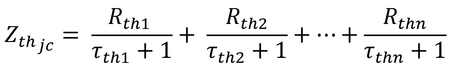
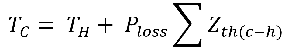
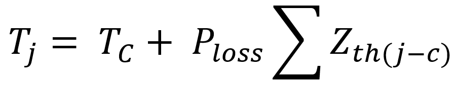
C4. Thermal Modeling
This work does not include extensive step-by-step thermal simulation. The thermal modeling approach for power electronic converters, on the other hand, is detailed in [5], [6][5][6]. The accuracy of the junction and case temperature estimation is the major topic of this work. The dynamic thermal model of junction-to-case, case-to-heatsink, and heatsink-to-ambient temperature characteristics is necessary for accurate temperature-dependent modeling of the inverter semiconductors. The thermal resistances (Rth) and capacitances (Cth) of the semiconductor layers are the most important components of the thermal model. The datasheet has Rth and Cth values which are standard for the corresponding switches. The junction temperature (Tj) and case temperature (Tc) and heatsink temperature (Th) can be calculated using the values of Rth and Cth by following Eq. (12) – Eq. (16):
 |
(12) |
|
(13) |
|
|
(14) |
|
 |
(15) |
 |
(16) |
(12)
![]()
(13)
![]()
(14)
(15)
(16)
where Zth(j-c) is the junction to case thermal resistance (°C/W), Zth(c-h) is the case to heatsink thermal resistance (°C/W), Tclnt is the inlet coolant temperature and Rth(c-h) is the equivalent thermal resistance between case and heatsink.
The physical structure of a semiconductor's thermal model is usually represented as a cascaded RC network [7] which known as Foster networks [8], as seen in FigFigure 2. 2. Foster network is the preferred technique for the semiconductor thermal analysis. The RC branches of the Foster network do not represent any physical layer of semiconductor switch, but the mathematical model of Foster network acts like a Cauer model with less complexity but still good accuracy. The transfer functions are used to calculate the junction temperature in MATLAB/Simulink [9].
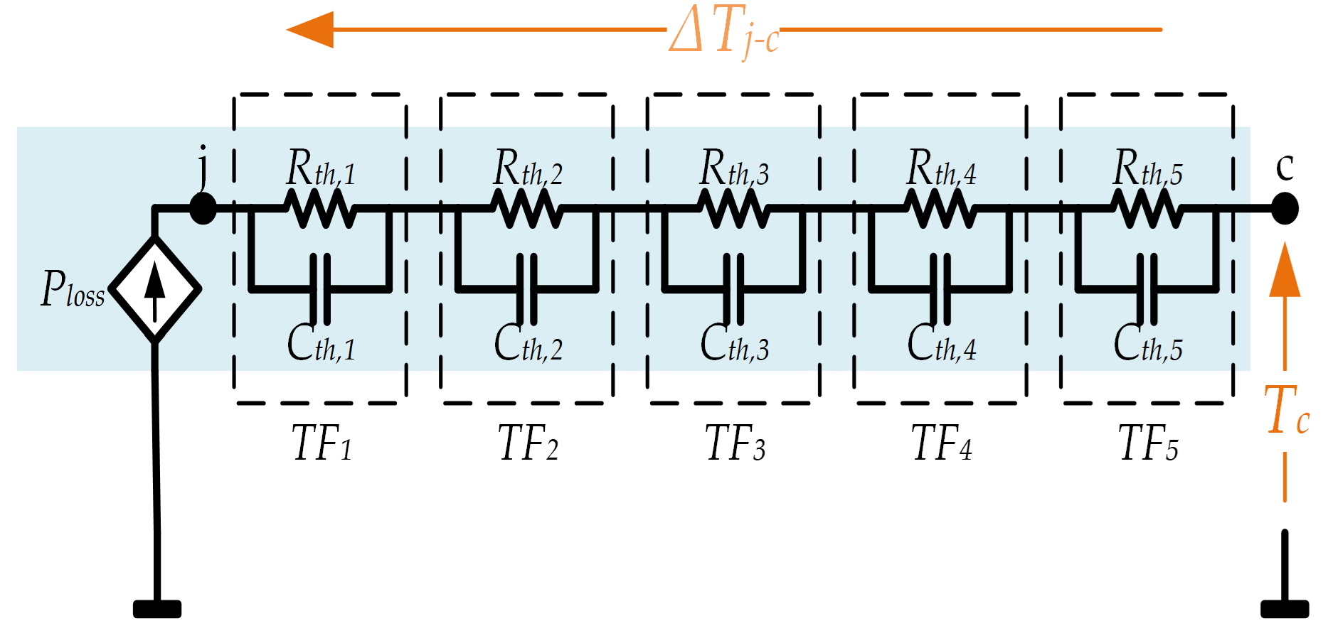
FigFigure 2. 2: 5-layer semiconductor foster network.
E5. Electrical Losses Performance
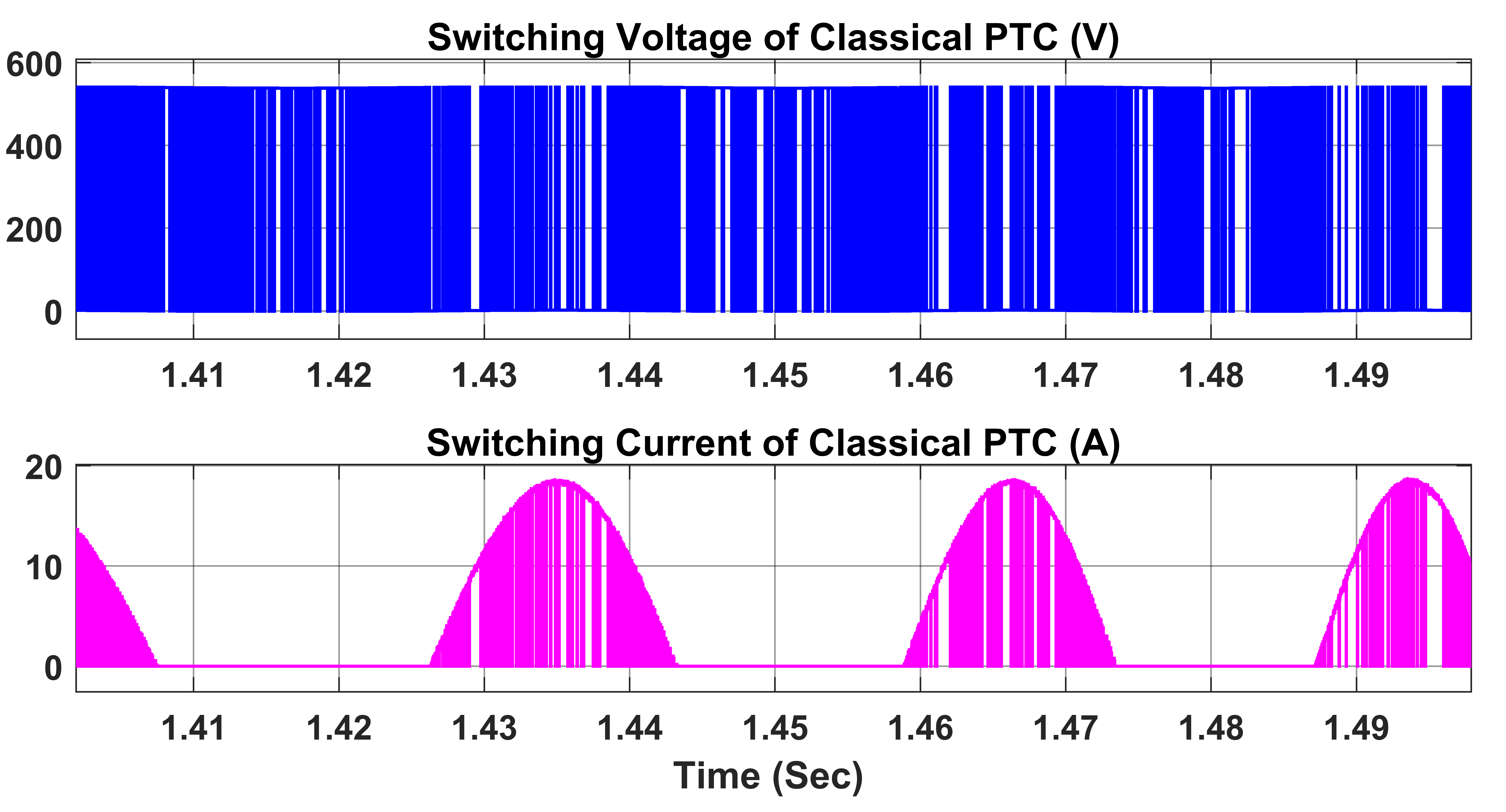
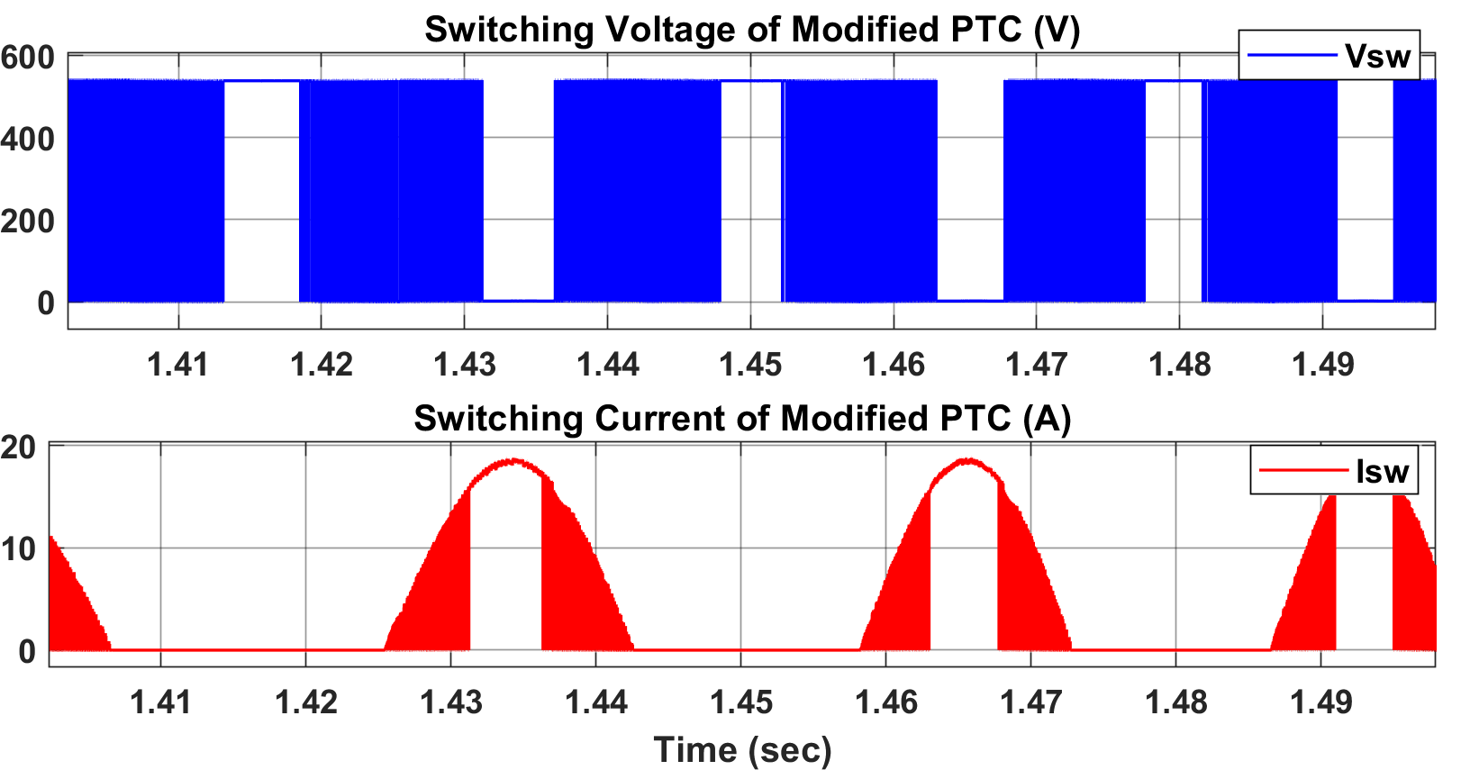
The switching currents of MOSFET in different control techniques are compared in FigFigure 3. 3. It is evident that some clamping occurred throughout the changeover process. The reason for this is that while switching, the zero-vector sequence is used. The zero-vector selection method has a direct impact on the inverter switch current waveforms. Fig.Figure 4 4 shows the switching losses profile for the upper switch of phase-A half-bridge module of the inverter, both for the suggested technique and for the traditional approach. A significant reduction can be noticed in On-Off switching energy losses.
 (a)
(a)
 (b)
(b)
Fig. 3Figure 3. The switching current and voltage profile for MOSFET: (a) Classical PTC, (b) Modified PTC
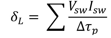
The switching losses for both PTC approaches were calculated using the switching loss figure (δL) presented in Eq. (17) where ∆τp represents the time period of p number of fundamental cycles. In this work, we consider 15 fundamental cycles. If only the upper side switch of phase-A is considered, the switch voltage and current are doubled anytime that switch transitions.
 |
(17) |
(17)
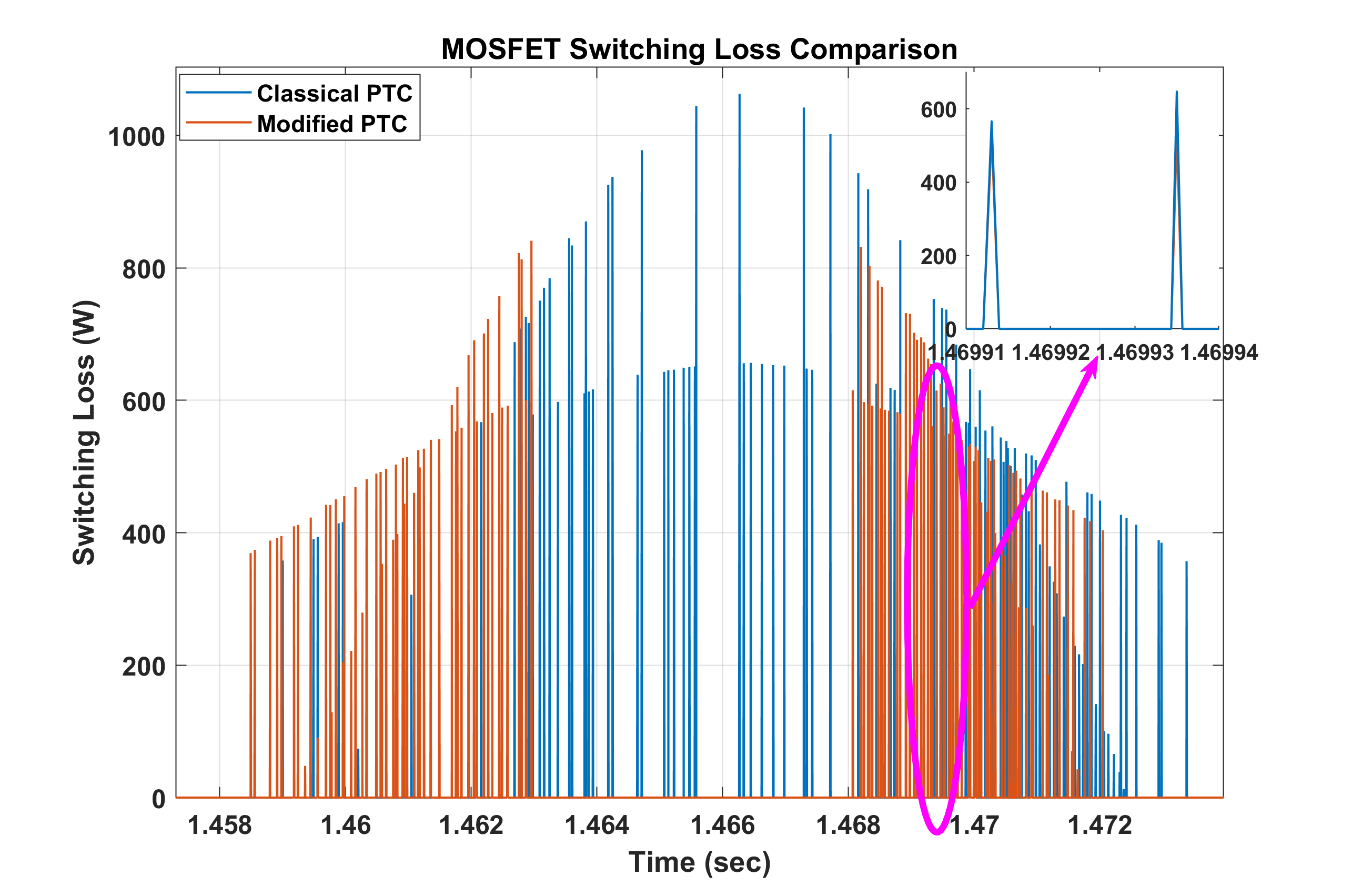 FigFigure 4. 4: Switching losses profile comparison for SiC MOSFET switch.
 Fig
Fig
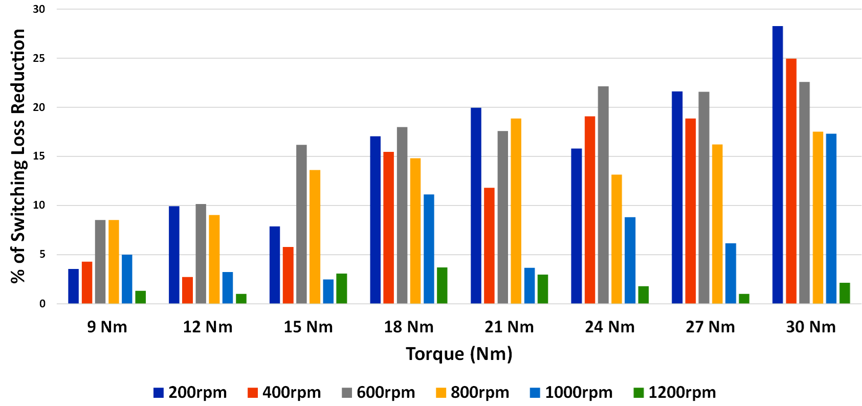
Figure 5. 5: Percentage of switching losses reduction comparison by using modified PTC.
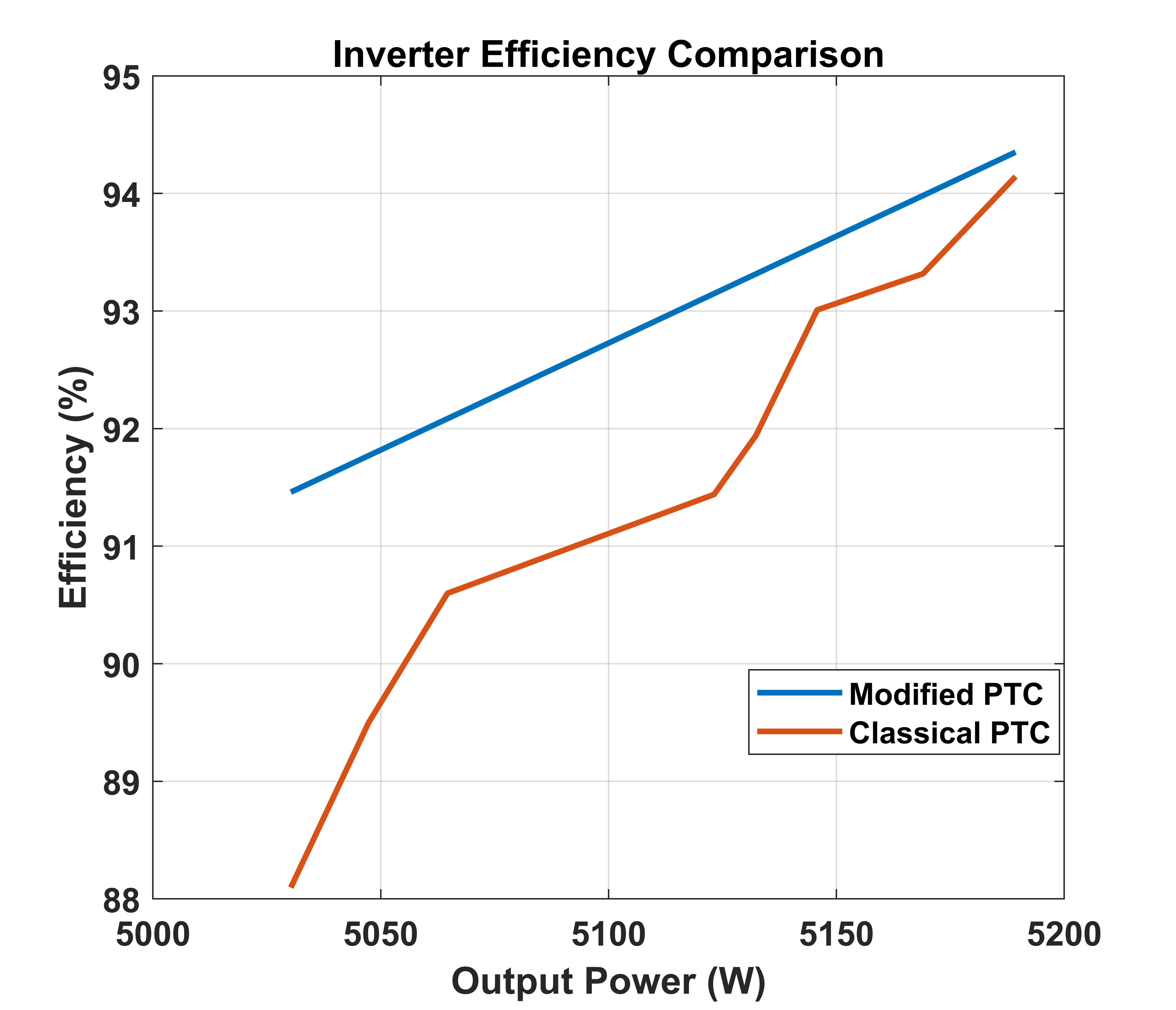
FigFigure 6. 6: Traction inverter efficiency for 5.5kW motor drive operation.
From Fig. 5Figure 5, it is noticeable that the δL is significantly reduced in the low speed-high torque region. At rated speed the controller performance is not significant enough to reduce the switching losses. Numerically, it is estimated that the switching losses are significantly reduced by 20% using the modified PTC. The efficiency comparison is also shown in Fig. 6 Figure 6 which indicates a 2-4% increase in efficiency by using the modified PTC based on reduced active voltage vector.
F6. Thermal Performance
The semiconductor device losses are impacted by the thermal performance. The magnified junction temperature profile is shown in Fig.7 Figure 7 during the torque reference change from 15 Nm to 30 Nm. The overall peak of Tj cycle is reduced up to 3% on average for 3.8sec operation. The case temperature is shown in Fig. 8Figure 8 which also depicts that the average case temperature during modified PTC is around 6% less than the classical PTC strategy. Similarly, the heatsink temperature is also reduced for modified PTC which is shown in FigFigure 9. 9.
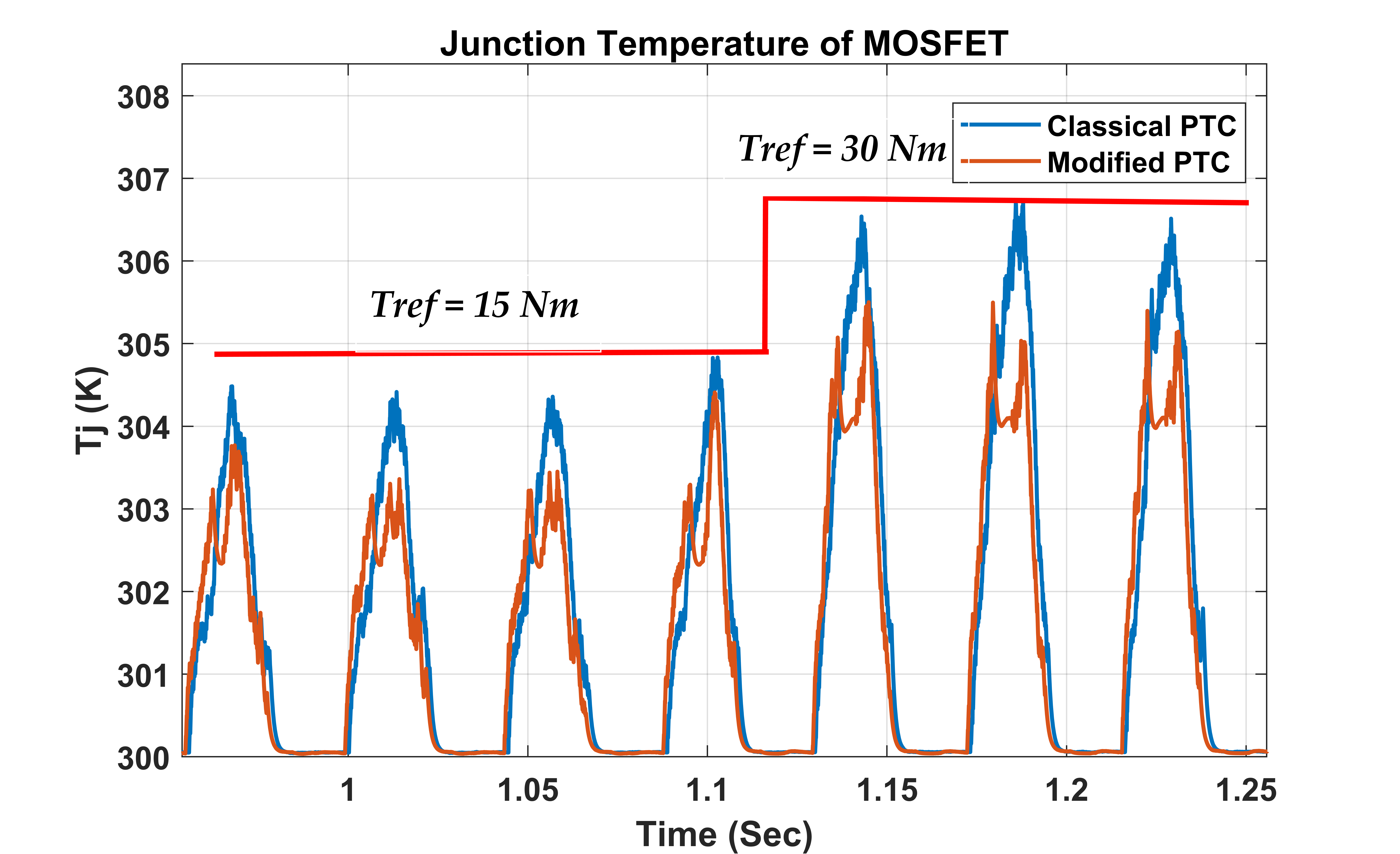
FigFigure 7. 7: Junction temperature transition when the torque changed from 15Nm to 30Nm for different PTC strategy.
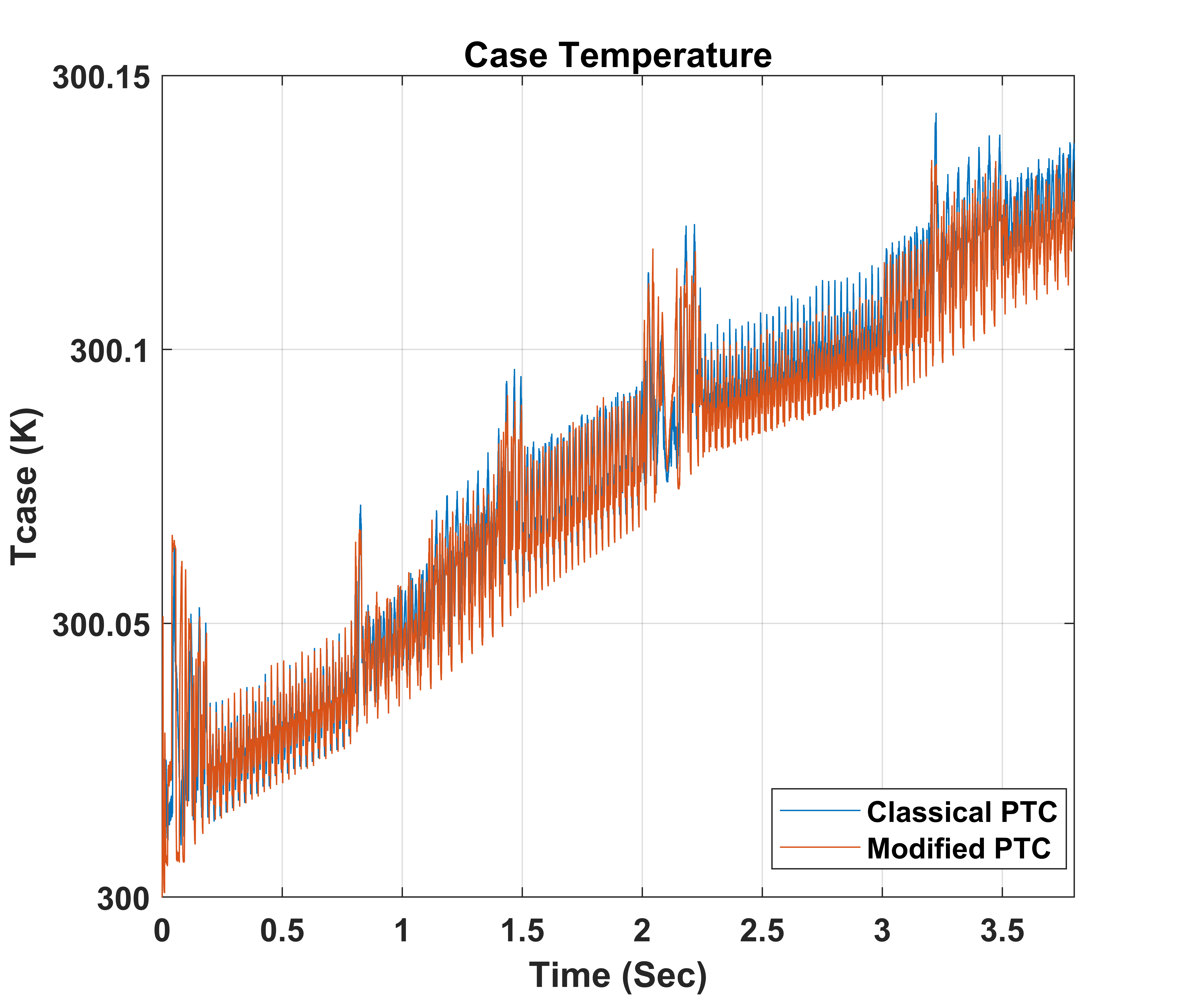 FigFigure 8. 8: The case temperature profile in two different control techniques.
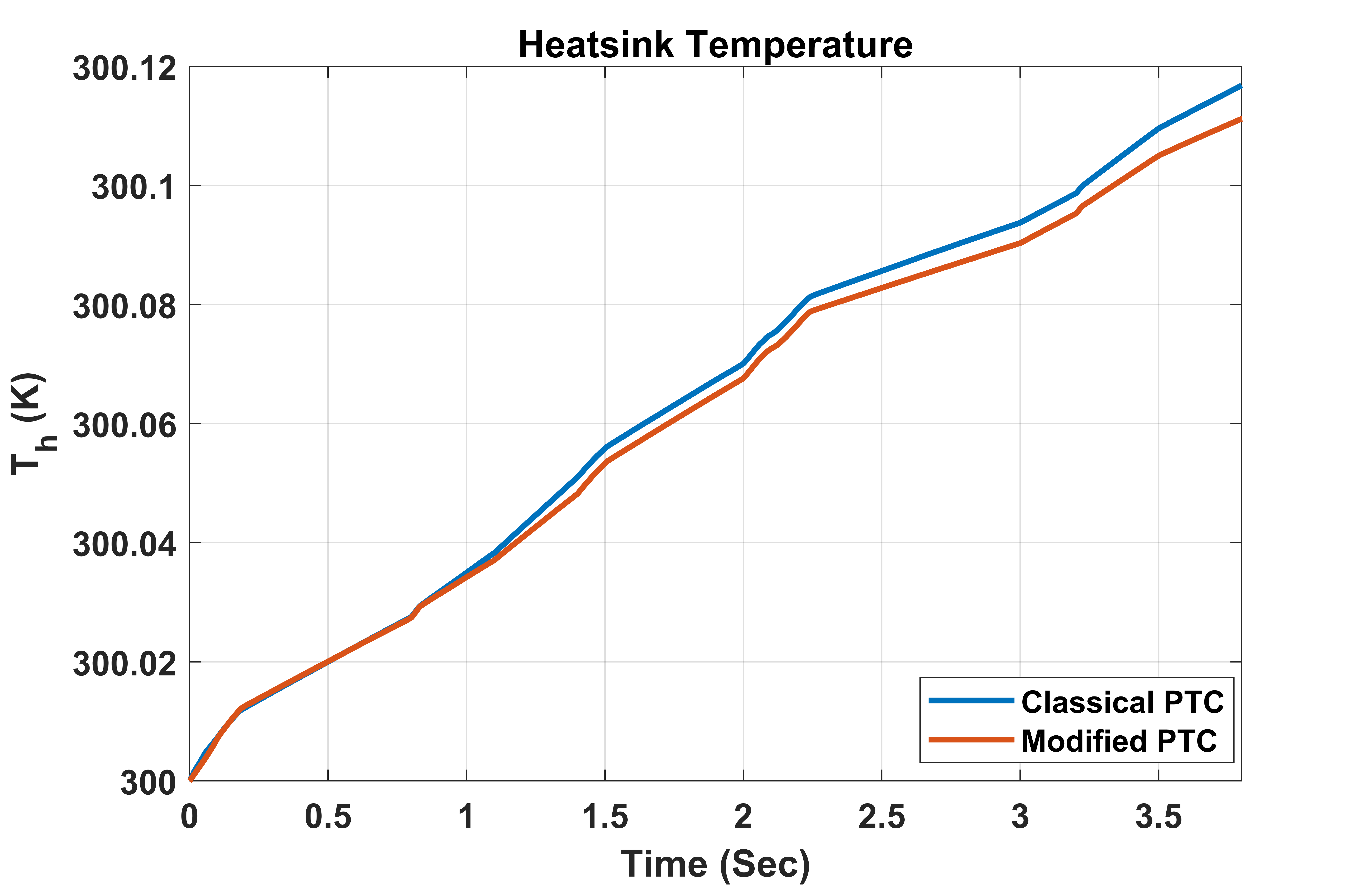 Fig. 9: Figure 9. The heatsink temperature profile in two different control techniques.
Reference
[1]. N. Torsæter, “Evaluation of Switching Characteristics, Switching Losses and Snubber Design for a Full SiC Half-Bridge Power Module.” NTNU, 2016.
[2]. Rasool et al., "Design Optimization and Electro-Thermal Modeling of an Off-Board Charging System for Electric Bus Applications," in IEEE Access, vol. 9, pp. 84501-84519, 2021
[3]. Zhou, M. S. Khanniche, P. Igic, S. M. Towers, and P. A. Mawby, “Power loss calculation and thermal modelling for a three phase inverter drive system,” J. Electr. Syst., pp. 33–46, 2005.
[4]. Richmond, “Hard Switched Silicon IGBT’s? Cut Switching Losses in Half with Silicon Carbide Schottky Diodes,” Mater. CREE, vol. 1, 2003.
[5]. Urkizu, J.; Mazuela, M.; Alacano, A.; Aizpuru, I.; Chakraborty, S.; Hegazy, O.; Vetten, M.; Klink, R. Electric Vehicle Inverter Electro-Thermal Models Oriented to Simulation Speed and Accuracy Multi-Objective Targets. Energies 2019, 12, 3608.
[6]. Chakraborty et al., "Scalable Modeling Approach and Robust Hardware-in-the-Loop Testing of an Optimized Interleaved Bidirectional HV DC/DC Converter for Electric Vehicle Drivetrains," in IEEE Access, vol. 8, pp. 115515-115536, 2020.
[7]. Sintamarean, F. Blaabjerg, and H. Wang, ``A novel electro-thermal model for wide bandgap semiconductor based devices,'' in Proc. 15th Eur. Conf. Power Electron. Appl. (EPE), Sep. 2013, pp. 1_10.
[8]. Ciceo, Y. Mollet, M. Sarrazin, J. Gyselinck, H. Van der Auweraer, and C. Martis, ``Model-based design and testing for electric vehicle driveability analysis,'' in Proc. IEEE 16th Int. Conf. Environ. Electr. Eng. (EEEIC), Jun. 2016, pp. 1_4.
[9]. Hegazy, R. Barrero, J. Van Mierlo, M. E. Baghdad, P. Lataire and T. Coosemans, "Control, analysis and comparison of different control strategies of electric motor for battery electric vehicles applications," 2013 15th European Conference on Power Electronics and Applications (EPE), 2013, pp. 1-13, doi: 10.1109/EPE.2013.6631906.
References
- N. Torsæter, “Evaluation of Switching Characteristics, Switching Losses and Snubber Design for a Full SiC Half-Bridge Power Module.” NTNU, 2016.
- Rasool et al., "Design Optimization and Electro-Thermal Modeling of an Off-Board Charging System for Electric Bus Applications," in IEEE Access, vol. 9, pp. 84501-84519, 2021
- Zhou, M. S. Khanniche, P. Igic, S. M. Towers, and P. A. Mawby, “Power loss calculation and thermal modelling for a three phase inverter drive system,” J. Electr. Syst., pp. 33–46, 2005.
- Richmond, “Hard Switched Silicon IGBT’s? Cut Switching Losses in Half with Silicon Carbide Schottky Diodes,” Mater. CREE, vol. 1, 2003.
- Urkizu, J.; Mazuela, M.; Alacano, A.; Aizpuru, I.; Chakraborty, S.; Hegazy, O.; Vetten, M.; Klink, R. Electric Vehicle Inverter Electro-Thermal Models Oriented to Simulation Speed and Accuracy Multi-Objective Targets. Energies 2019, 12, 3608.
- Chakraborty et al., "Scalable Modeling Approach and Robust Hardware-in-the-Loop Testing of an Optimized Interleaved Bidirectional HV DC/DC Converter for Electric Vehicle Drivetrains," in IEEE Access, vol. 8, pp. 115515-115536, 2020.
- Sintamarean, F. Blaabjerg, and H. Wang, ``A novel electro-thermal model for wide bandgap semiconductor based devices,'' in Proc. 15th Eur. Conf. Power Electron. Appl. (EPE), Sep. 2013, pp. 1_10.
- Ciceo, Y. Mollet, M. Sarrazin, J. Gyselinck, H. Van der Auweraer, and C. Martis, ``Model-based design and testing for electric vehicle driveability analysis,'' in Proc. IEEE 16th Int. Conf. Environ. Electr. Eng. (EEEIC), Jun. 2016, pp. 1_4.
- Hegazy, R. Barrero, J. Van Mierlo, M. E. Baghdad, P. Lataire and T. Coosemans, "Control, analysis and comparison of different control strategies of electric motor for battery electric vehicles applications," 2013 15th European Conference on Power Electronics and Applications (EPE), 2013, pp. 1-13, doi: 10.1109/EPE.2013.6631906.