Your browser does not fully support modern features. Please upgrade for a smoother experience.
Please note this is a comparison between Version 2 by Camila Xu and Version 1 by Berke Ogulcan Parlak.
Pipelines are considered the most efficient way to transport oil and gas resources. However, this advantage of pipelines may be lost if pipeline integrity is not ensured. Geometric deformations, metal losses, and crack-type anomalies caused by various reasons in the pipeline threaten the integrity of the pipeline. Therefore, it is important to examine the causes of occurrence, hazard potentials, and management methods of pipeline anomalies as part of pipeline integrity management.
- oil
- natural gas
- pipeline
- anomaly
- geometric deformation
- metal loss
- cracking
1. Introduction
Today’s main energy sources are petroleum and natural gas. If the primary energy consumption in the United States (US) is analyzed based on sources, oil accounts for 35% of the total and natural gas accounts for 23% [1]. The transportation of these energy sources is important in terms of accessing energy. Pipelines are considered the most efficient way to transport oil and gas resources [2]. Furthermore, it surpasses other modes of transportation such as road, train, air, and sea when traveling long distances in terms of convenience, cost, safety, and environmental friendliness. As a result, almost all natural gas is transported via pipelines. For instance, about 97% of the natural gas and oil transported in Canada is carried through pipelines. As of 2017, the entire length of gas and oil pipelines in the world is estimated to be approximately 3,550,000 km, with gas pipelines measuring 2,965,600 km in length and oil pipelines measuring 584,000 km [3].
Oil and natural gas pipelines spanning kilometers are susceptible to accidents for a variety of reasons. The main causes of pipeline accidents are corrosion, gouges, plain and kinked dents, smooth dents on welds, smooth dents with other types of anomalies, manufacturing defects in the pipe body, girth and seam weld defects, and cracking [4]. If these anomalies are not addressed, they may result in pipeline failures such as leaks or ruptures, resulting in increases in costs, environmental risks, and even catastrophic accidents. According to the data of the US Department of Transportation Pipeline and Hazardous Materials Safety Administration, there were 681 accidents labeled as serious in the US between 2002 and 2021. In these accidents, 260 people lost their lives, 1112 people were injured and USD11,043,742,158 financial losses occurred. Apart from that, as a result of the rupture of the pipeline in Michigan in July 2010, 1,000,000 barrels of oil leaked and caused great damage to the environment [5].
2. Types of Pipeline Anomalies
Anomalies occur in oil and natural gas pipelines for various reasons. The formation process of these anomalies can be examined in three classes. While corrosion anomalies in the pipeline occur depending on time, anomalies caused by mechanical damage or disasters occur independent of time. Anomalies originating from fabrication such as bends, buckles, and wrinkles are classified as stable. The management process of anomalies is associated with these formation processes. Therefore, the formation process of anomalies is important for pipeline integrity management (PIM). PIM is a systematic approach to ensuring the safe operation of pipelines. This process involves identifying and mitigating potential hazards that could lead to pipeline accidents. PIM can be divided into three main categories: assessment, planning, and management. Assessment involves close observation of the internal and external sections of pipelines to identify any anomalies and determine the overall condition of the pipelines. Planning encompasses all the activities aimed at maintaining or repairing pipelines, such as defining operations and procedures, conducting inspections, and performing maintenance and monitoring. Management includes tasks such as data management audits, fit-for-service evaluations, burst pressure assessments, and third-party verification. Through this comprehensive approach, PIM plays a vital role in protecting the environment and communities. Pipeline anomalies can cause structural stress on the pipeline and increase the risk of pipeline failure. As such, it is important to examine the causes of occurrence, hazard potentials, and management methods of pipeline anomalies as part of PIM.2.1. Geometric Deformation
The pipeline may be subject to operational distortions such as pressure fluctuations, excessive mechanical forces, poor workmanship, or third-party damage. These distortions are the main source of geometric deformations in the pipeline. Geometric deformations in the pipeline can be listed as metal movement, denting, metal removal, cold working of the underlying metal, and puncturing [6]. Among them, the dent is one of the three most common typical anomalies (i.e., corrosion, dents, and cracks) encountered in oil and gas pipelines [7]. Dents are formed on the surface of pipes due to external loads such as excavation activities during the construction of pipelines [8]. Dents can be classified as plaint dents [9] and composite dents [10]. Plaint dents pose no major threat to pipeline integrity (PI), whereas composite dents pose a greater threat to PI [11]. Dents cause stress and strain concentration [12][13]. Therefore, dent management is an important issue for PIM. Different approaches can be used for dent management. Warman et al. [14] presented an approach that Duke Energy Gas Transmission has implemented for dent management. This approach involved characterizing dents and mechanical damage in the pipeline system by integrating data collected from high-resolution in-line inspection (ILI) tools operated over 2000 miles. Torres and Piazza [15] developed a new engineering tool for the integrity management of dents using finite element analysis. This tool was used to develop fatigue life trends. There are other studies on the management and characterization of geometric deformations in the literature [16][17][18]. However, the most common use for detecting geometric deformations is pigs with mechanical contact (MC) probes.2.2. Metal Loss
The pipeline may be exposed to rusting, cavitation, and corrosive substances over time. These reasons are the main source of metal losses in the pipeline. Metal loss can manifest itself as gouging, corrosion, and erosion. Among them, corrosion is one of the most important problems affecting safety in oil and gas pipelines, as shown in Figure 1, and accounts for approximately 30% of all equipment failures [19]. Corrosion continually reduces the pipe-wall thickness and can significantly accelerate the formation of leaks [20]. Accurate estimation of the corrosion rate is of primary importance for integrity management planning of a pipeline [22]. Machine-learning-based approaches are suitable approaches to predict the behavior of corrosion occurring in pipelines [23]. Hamed et al. [24] proposed a nonparametric calibration model based on k-nearest neighbor interpolation to improve field data collected from ultrasonic testing (UT) and magnetic flux leakage (MFL). The model improved the accuracy of pipeline wall-thickness measurements. In this way, the life of the critical part of the pipeline can be better predicted. ILI tools are widely used for corrosion detection in oil and gas pipelines [25]. ILI is accepted as the optimum approach to detect and characterize the anomalies as well as reveal the growth rate information of the active anomalies in the pipeline [26]. Low and Selman [27] outlined the capabilities and limitations of ILI methods used to inspect corroded pipelines. Huyse et al. [28] presented a study that tested the performance of various ILI methods on top of the line (TOL) corrosion. According to the study, MFL technology showed the best success in detecting TOL corrosion. Palmer and Schneider [29] revealed that hybrid sensor technology, which combines different ILI methods such as UT, electromagnetic acoustic transducer (EMAT), MFL, and eddy current (EC), will be effective in sizing complex metal losses.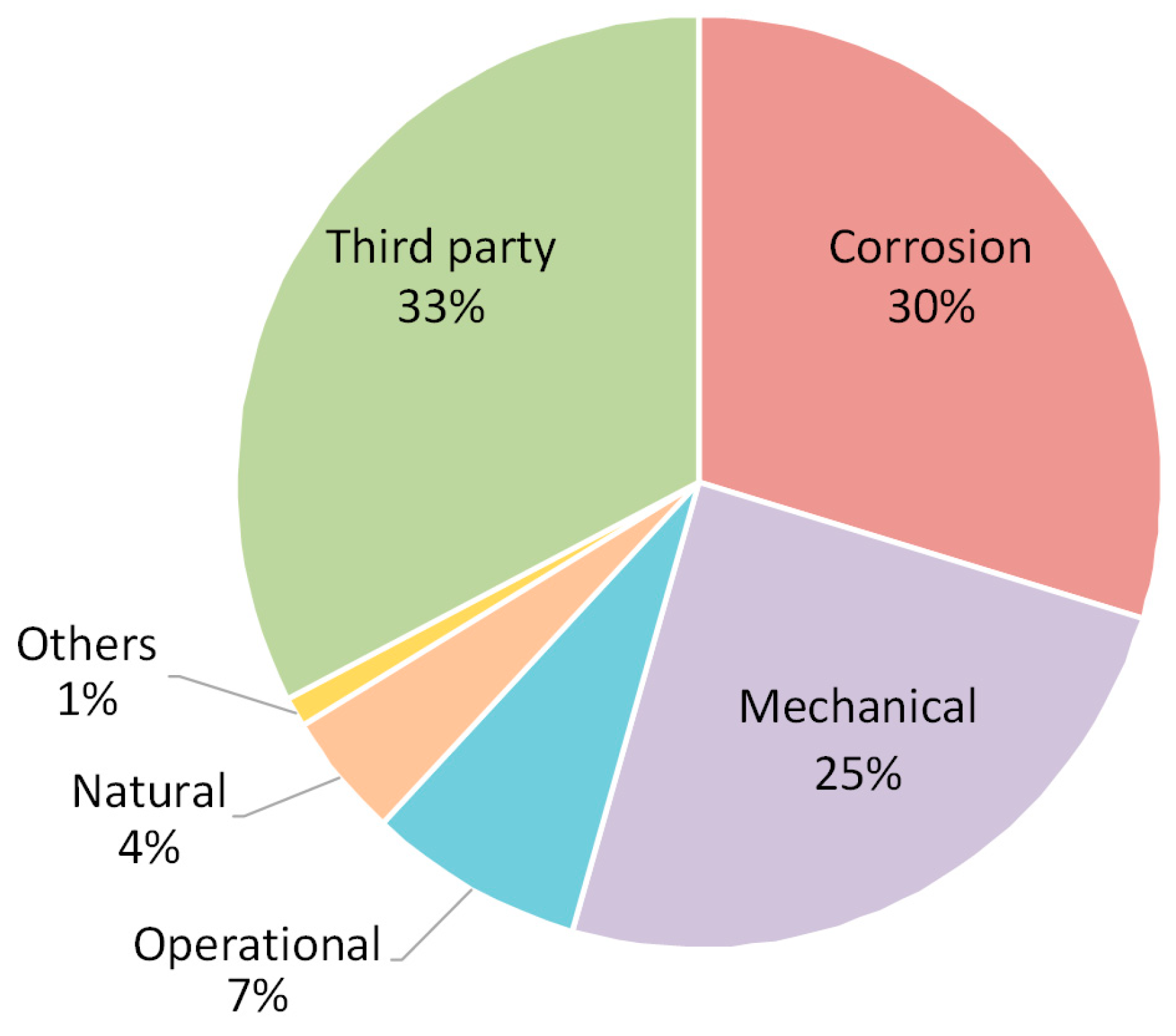
2.3. Cracking
Pipelines are constantly exposed to environmental effects, external loads, and ground movements due to their nature. These effects are the main source of cracking in pipelines. In addition, cracks often occur in a hybrid form in oil and natural gas pipelines. Examples of these hybrid anomalies are crack in corrosion (CIC), stress corrosion cracking (SCC), and crack in dent (CID). Crack-like anomalies may occur simultaneously with corrosion anomalies and represent a new hybrid form of an anomaly called CIC [30]. Bedairi et al. [31] presented a study for predicting the failure pressures of CIC anomalies to determine the applicability of PI assessment methods. The predicted failure pressures were conservative when compared to the experimental results, with a mean difference of 17.4% for five different CIC anomalies with various depths. SCC is defined as the growth of crack formation in a corrosive environment. These cracks often have a high aspect ratio and pose a major threat to the PI [32]. As a result, estimating the crack growth rate (CGR) of SCCs is critical. Song [33] developed a mathematical model for this purpose. The developed model was used to predict CGRs with two methods called the potentiodynamic polarization curve and the Butler–Volmer equation. The potentiodynamic polarization curve was good at predicting high CGRs, while the Butler–Volmer equation was good at predicting low CGRs. Ryakhovskikh and Bogdanov [34] determined the conditions for operating a pipeline with SCC cracks by considering the temporal variations of the CGR to certain accident statistics. The findings showed that pipes with crack depths between 0.1 and 0.25 δ (where δ is the pipe-wall thickness) could be left operating until a scheduled inspection if the CGR is estimated. Palmer et al. [35] presented a case study on CGR estimation based on repeated EMAT data. The method simply involved passing the EMAT sensor over the relevant crack periodically. Estimated CGRs determined during the presented case study showed reasonable results in line with the available literature. Dents adjacent to welds can cause cracks to develop in the welds and cause a combined anomaly referred to as a CID or dent–crack anomaly [36]. These anomalies can lead to major accidents such as bursts in the pipeline. The effect of the location of the CID anomaly on burst pressure has been discussed in the literature [37][38][39]. ILI is frequently used in the management of oil and gas pipeline cracks. UT has proven to be the most suitable and reliable technology for crack detection in pipelines [40]. However, the application of UT technology requires a liquid medium. Therefore, EMAT is used as a substitute for UT technology in gas pipelines.References
- Fichman, B.T. Annual Energy Review 2009 (No. DOE/EIA-0384); Technical Report; U.S. Department of Energy Office of Scientific and Technical Information: Washington, DC, USA, 2010.
- Zhou, W. System Reliability of Corroding Pipelines. Int. J. Press. Vessel. Pip. 2010, 87, 587–595.
- Lu, H.; Iseley, T.; Behbahani, S.; Fu, L. Leakage Detection Techniques for Oil and Gas Pipelines: State-of-the-Art. Tunn. Undergr. Sp. Technol. 2020, 98.
- Vilkys, T.; Rudzinskas, V.; Prentkovskis, O.; Tretjakovas, J.; Višniakov, N.; Maruschak, P. Evaluation of Failure Pressure for Gas Pipelines with Combined Defects. Metals 2018, 8, 346.
- Liu, S.; Liang, Y. Statistics of Catastrophic Hazardous Liquid Pipeline Accidents. Reliab. Eng. Syst. Saf. 2021, 208, 107389.
- The American Society of Mechanical Engineers. ASME B31. 4. Pipeline Transportation Systems for Liquid Hydrocarbons and Other Liquids; The American Society of Mechanical Engineers: New York, NY, USA, 2009.
- Shuai, Y.; Wang, X.-H.; Shuai, J.; Zhao, Y.-Z.; Zhang, X.; Tang, C. Mechanical Behavior Investigation on the Formation of the Plain Dent of an API 5L L245 Pipeline Subjected to Concentrated Lateral Load. Eng. Fail. Anal. 2020, 108, 104189.
- Alexander, C.R. Review of Experimental and Analytical Investigations of Dented Pipelines. In Proceedings of the ASME Conference on Pressure Vessel and Piping Operations, Applications and Components, New York, NY, USA, 1–3 February 1999; pp. 197–209.
- Kec, J.; Cerny, I. Stress-Strain Assessment of Dents in Wall of High Pressure Gas Pipeline. Procedia Struct. Integr. 2017, 5, 340–346.
- Akbari Alashti, R.; Jafari, S.; Hosseinipour, S.J. Experimental and Numerical Investigation of Ductile Damage Effect on Load Bearing Capacity of a Dented API XB Pipe Subjected to Internal Pressure. Eng. Fail. Anal. 2015, 47, 208–228.
- Zhang, P.; Lan, H.; Dou, X.; Wang, J.; Zha, S. Review of Load-Bearing Capacity of Dented Pipes under Typical Loads. Eng. Fail. Anal. 2021, 120.
- Wu, Y.; Xiao, J.; Zhang, P. The Analysis of Damage Degree of Oil and Gas Pipeline with Type II Plain Dent. Eng. Fail. Anal. 2016, 66, 212–222.
- Yan, S.; Shen, X.; Jin, Z.; Ye, H. On Elastic-Plastic Collapse of Subsea Pipelines under External Hydrostatic Pressure and Denting Force. Appl. Ocean Res. 2016, 58, 305–321.
- Warman, D.J.; Johnston, D.; Mackenzie, J.D.; Rapp, S.; Travers, B. Management of Pipeline Dents and Mechanical Damage in Gas Pipelines. In Proceedings of the Volume 2: Integrity Management; Poster Session; Student Paper Competition, Calgary, AB, Canada, 1 January 2006; ASMEDC: New York, NY, USA, 2006; Volume 2, pp. 551–560.
- Tiku, S.; Eshraghi, A.; Semiga, V.; Torres, L.; Piazza, M. Improved Pipeline Dent Integrity Management. In Proceedings of the Volume 1: Pipelines and Facilities Integrity, Calgary, AB, Canada, 26 September 2016; American Society of Mechanical Engineers: New York, NY, USA, 2016; Volume 1, pp. 1–10.
- Co, V.; Ironside, S.; Ellis, C.; Wilkie, G. Characterization of Mechanical Damage Through Use of the Tri-Axial Magnetic Flux Leakage Technology. In Proceedings of the Proceedings of the 6th International Pipeline Conference, Calgary, AB, Canada, 1 January 2006; ASMEDC: New York, NY, USA, 2006; Volume 2, pp. 677–684.
- Wang, R.Y.; Kania, R.; Arumugam, U.; Gao, M. Characterization of Topside Mechanical Damage. In Proceedings of the 10th International Pipeline Conference, Calgary, AB, Canada, 29 September 2014; American Society of Mechanical Engineers: New York, NY, USA, 2014.
- Torres, L.A.; Fowler, M.J.; Stenerson, J.G. Assessment of In-Line Inspection Performance and Interpretation of Field Measurements for Characterization of Complex Dents. In Proceedings of the Volume 1: Pipelines and Facilities Integrity, Calgary, AB, Canada, 26 September 2016; American Society of Mechanical Engineers: New York, NY, USA, 2016; pp. 1–8.
- Zakikhani, K.; Nasiri, F.; Zayed, T. A Review of Failure Prediction Models for Oil and Gas Pipelines. J. Pipeline Syst. Eng. Pract. 2020, 11, 03119001.
- Wright, R.F.; Lu, P.; Devkota, J.; Lu, F.; Ziomek-Moroz, M.; Ohodnicki, P.R. Corrosion Sensors for Structural Health Monitoring of Oil and Natural Gas Infrastructure: A Review. Sensors 2019, 19, 3964.
- Zakikhani, K.; Zayed, T.; Abdrabou, B.; Senouci, A. Modeling Failure of Oil Pipelines. J. Perform. Constr. Facil. 2020, 34, 04019088.
- Huyse, L.; van Roodselaar, A. Effects of Inline Inspection Sizing Uncertainties on the Accuracy of the Largest Features and Corrosion Rate Statistics. In Proceedings of the 2010 8th International Pipeline Conference, Calgary, AB, Canada, 1 January 2010; ASMEDC: New York, NY, USA, 2010; Volume 4, pp. 403–413.
- Soomro, A.A.; Mokhtar, A.A.; Kurnia, J.C.; Lashari, N.; Lu, H.; Sambo, C. Integrity Assessment of Corroded Oil and Gas Pipelines Using Machine Learning: A Systematic Review. Eng. Fail. Anal. 2022, 131, 105810.
- Hamed, Y.; Shafie, A.; Mustaffa, Z.; Rusma, N. Error-Reduction Approach for Corrosion Measurements of Pipeline Inline Inspection Tools. Meas. Control 2019, 52, 28–36.
- Rathod, V.R.; Anand, R.S.; Ashok, A. Comparative Analysis of NDE Techniques with Image Processing. Nondestruct. Test. Eval. 2012, 27, 305–326.
- Brockhaus, S.; Ginten, M.; Klein, S.; Teckert, M.; Stawicki, O.; Oevermann, D.; Meyer, S.; Storey, D. In-Line Inspection (ILI) Methods for Detecting Corrosion in Underground Pipelines. In Underground Pipeline Corrosion; Elsevier: Amsterdam, The Netherlands, 2014; pp. 255–285. ISBN 9780857095091.
- Low, A.; Selman, C. In-Line Inspection Programs for Corroded Pipelines. In Proceedings of the Annual Conference of the Australasian Corrosion Association 2013: Corrosion and Prevention, Brisbane, Australia, 10–13 November 2013; pp. 588–599.
- Huyse, L.; van Roodselaar, A.; Onderdonk, J.; Wimolsukpirakul, B.; Baker, J.; Beuker, T.; Palmer, J.; Jemari, N.A. Improvements in the Accurate Estimation of Top of the Line Internal Corrosion of Subsea Pipelines on the Basis of In-Line Inspection Data. In Proceedings of the 2010 8th International Pipeline Conference, Calgary, AB, Canada, 1 January 2010; ASMEDC: New York, NY, USA, 2010; Volume 1, pp. 75–82.
- Palmer, J.; Schneider, E. Reliable Sizing of Complex Metal Loss through Combined ILI Data Sets for Internal & External Anomalies in Gaseous & Liquid. In Proceedings of the 8th Pipeline Technology Conference, Berlin, Germany, 8–11 May 2013.
- Cronin, D.; Plumtree, A.; Sen, M.; Kania, R. Assessment of Crack in Corrosion Defects in Natural Gas Transmission Pipelines. In Proceedings of the 2008 7th International Pipeline Conference, Calgary, AB, Canada, 1 January 2008; ASMEDC: New York, NY, USA, 2008; Volume 2, pp. 557–565.
- Bedairi, B.; Cronin, D.; Hosseini, A.; Plumtree, A. Failure Prediction for Crack-in-Corrosion Defects in Natural Gas Transmission Pipelines. Int. J. Press. Vessel. Pip. 2012, 96–97, 90–99.
- Manfredi, C.; Otegui, J. Failures by SCC in Buried Pipelines. Eng. Fail. Anal. 2002, 9, 495–509.
- Song, F.M. Predicting the Mechanisms and Crack Growth Rates of Pipelines Undergoing Stress Corrosion Cracking at High PH. Corros. Sci. 2009, 51, 2657–2674.
- Ryakhovskikh, I.V.; Bogdanov, R.I. Model of Stress Corrosion Cracking and Practical Guidelines for Pipelines Operation. Eng. Fail. Anal. 2021, 121.
- Palmer, M.; Davies, C.; Ginten, M.; Palmer-Jones, R. Detection of Crack Initiation Based on Repeat In-Line Inspection. In Proceedings of the Volume 1: Pipelines and Facilities Integrity, Calgary, AB, Canada, 26–30 September 2016; American Society of Mechanical Engineers: New York, NY, USA, 2016; Volume 1, pp. 1–12.
- Rosenfeld, M.J. Proposed New Guidelines for ASME B31. 8 on Assessment of Dents and Mechanical Damage: Topical Report; Gas Research Institute: Des Plaines, IL, USA, 2001.
- Okodi, A.; Li, Y.; Cheng, J.J.R.; Kainat, M.; Yoosef-Ghodsi, N.; Adeeb, S. Effect of Location of Crack in Dent on Burst Pressure of Pipeline with Combined Dent and Crack Defects. J. Pipeline Sci. Eng. 2021, 1, 252–263.
- Rafi, A.; Silva, J.; Kenno, S.; Das, S.; Kania, R.; Wang, R.Y. Strength of Line Pipe With Dent and Crack Defect. In Proceedings of the Proceedings of the 8th International Pipelines Conference, Calgary, AB, Canada, 1 January 2010; ASMEDC: New York, NY, USA, 2010.
- Ghaednia, H.; Das, S.; Wang, R.; Kania, R. Safe Burst Strength of a Pipeline with Dent–Crack Defect: Effect of Crack Depth and Operating Pressure. Eng. Fail. Anal. 2015, 55, 288–299.
- Reber, K.; Beller, M.; Uzelac, N.I. How Do Defect Assessment Methods Influence the Choice and Construction of In-Line Inspection Tools. In Proceedings of the 4th International Pipeline Conference, Parts A and B., Calgary, AB, Canada, 1 January 2002; ASMEDC: New York, NY, USA, 2002; Volume B, pp. 2039–2044.
More