Your browser does not fully support modern features. Please upgrade for a smoother experience.
Please note this is a comparison between Version 2 by Dean Liu and Version 4 by olcay bay.
The OBC (on-board charger) is one of the interfacing parts of the EV (electric vehicle) that must interact with the external world via the connection to the utility grid or to dedicated electric vehicle supply equipment (EVSE) that is interfaced with the AC utility grid, ratings and requirements of which are beyond the control of manufacturers. For this reason, any vehicle occupying a built-in charger supposed follow certain regulations to be allowed in the market.
- on-board charger
- electric vehicle
- vehicle-to-grid (V2G)
1. Power Quality
For LV low-power equipment, limits are established in the IEC 61000-3-2 standard, where battery chargers are classified in Class A, whose scope encompasses all electrical equipment (both single-phase and three-phase) absorbing no more than 16 A (charging mode 1) and connected to the LV public network. For larger current levels, the reference standard is the IEC 61000-3-12 for electrical equipment absorbing more than 16 A and up to 75 A, thus encompassing the other two charging modes 2 and 3. Voltage harmonics and flicker resulting from interconnection of the OBC charger are regulated as per IEC 61000-3-3 and IEC 61000-3-11. The IEC power quality standards referred above focus on low frequency harmonics up to 40th. However, state-of-the-art power electronics converters with high switching frequency and low frequency distortions shift above the classical 40th harmonic frequency band to 2 kHz–150 kHz, namely in the supra-harmonics range [1]. Although this phenomenon is not addressed in the current version (2019) of IEC 61851-1, it is getting attention, e.g., IEC 61000-2-2:2017, of the scientific community [1].
2. Battery Pack Requirements
Due to the evaluation of battery pack systems, strict dimensional constraints on the OBCs are imposed during vehicle charging. Moreover, high-switching GaN-based OBC is subjected to cause a superimposed high-frequency ripple current on the battery pack system, and studies have depicted that batteries degrade faster under charging and discharging cycles with current ripples [2]. In [2][3], the long-term effects of superimposed current ripple at from 55 Hz up to 20 kHz on battery ageing using 18650 model batteries have been investigated. The results showed that, at the same number of cycles and same ripple current magnitude, the temperature rise of the batteries with highest frequency ripple is higher compared to the other specimens. Additionally, the BMS protection ranged in between 10–1 ms and cannot activate voltage protection timely to block the transient overcharge and over-discharge at frequencies above 100 Hz–1 kHz. Though specific requirements are not found in the literature, several requirements are listed from studies [2][3][4][5] for ensuring the proper reliability of a battery pack system: (a) <5% ripple current above 1 kHz frequency, (b) independent AC/DC conversion for lowering the ripple content on DC charge and discharge, and (c) ripple current superposition on various CC/CV charge/discharge modes for battery stack composed of 96 cells, as shown in Figure 1a and b. As lithium-ion batteries (LIB) are prone to lithium plating, it is important to reduce charging currents and ripple, particularly at a high state of charge level (SoC).
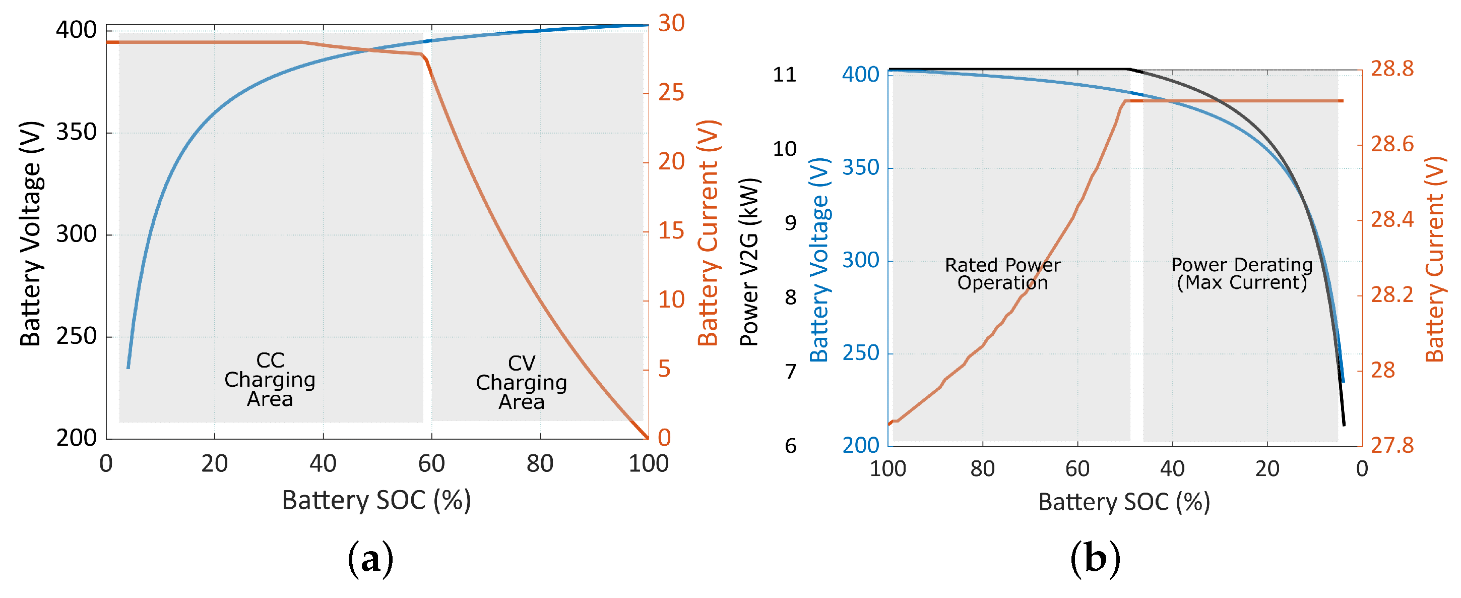
Figure 1. Typical battery current and voltage waveforms for (a) G2V, (b) V2G.
3. Electromagnetic Compatibility (EMC)
As a result of the high levels of switched currents and voltages as natural characteristics of a switching power supplies, they generate undesired electromagnetic emissions which are guided through conductors (frequency range of interest for conducted emissions: 150 kHz–30 MHz) or air (frequency range of interest for radiated emissions: 30 MHz–1 GHz) and which potentially lead to electromagnetic interference (EMI) with surrounding devices. Standard 61851-21-1 [6] defines electric vehicle on-board charger EMC requirements for conductive connection to an AC or DC supply, as per the methods described International Special Committee on Radio Interference–CISPR standards which apply to vehicles and electronic/electrical component intended for use in vehicles.
3.1. Conducted Emissions
IEC 61851-21-1 [6] defines measurements techniques and the conducted emission limits on AC or DC power lines. These guidelines distinguish between Class A (residential) and Class B (light industrial) environments, and set peak and quasi-peak limits for conducted emissions. As an automotive electronic product, essentially, limits defined by CISPR 25 and IEC 61000-6-3 [6] constitutes the basis of the OBC application. Conducted emission conformity tests also rely on the test methods, test apparatus and correction factors described in CISPR 12, CISPR 16 and CISPR 22 (replaced by CISPR 36 in 2017 [7]). Effective EMI filtering circuits are still necessary to limit the propagation of electrical noise, despite efforts to reduce conducted emissions through modulation schemes and soft-switching techniques [8].
3.2. Radiated Emissions
In addition to the requirements defined in CISPR 12, CISPR 36 [7] was developed based upon the need for a vehicle emissions standard covering the frequency range of 150 kHz to 30 MHz, excluding mild hybrid vehicles. Vehicles utilizing electric propulsion tend to produce emissions in the lower frequency bands not covered by CISPR 12 (a standard also for protection of off-board receivers at a 10-meter separation distance but in the frequency range of 30 MHz to 1000 MHz). In order to comply with the requirements for radiated disturbances, GaN-based OBC design needs to excel in layout techniques to reduce radiated emissions caused by switching oscillations.
4. V2G Functionality
Although bidirectional charging technology already exists, current editions of standards do not address bi-directional functions [9] to unlock the full capabilities of vehicle V2X features, e.g., requirements for anti-islanding protection [10]. The study reported in [11] reviews the status of V2G standards and addresses necessary improvements for widespread adoption of V2G functions. In summary, many V2X functions have not yet been fully commercialized, and research on GaN-based topologies for such functions is still in its early stages of development [12]. Table 1 provides an overview of the international standards relevant to on-board charging applications.
Table 1. International standards related to the OBC applications.
| Aspect | Standard | Description |
|---|---|---|
| General aspects | IEC 61851-1 | General requirements |
| EVSE | IEC 61851-22 | EV AC charging station |
| Connectors and inlets | IEC 62196-1 | General aspects |
| IEC 62196-2 | AC vehicle couplers | |
| Power quality | Current harmonic limits | |
| IEC 61000-3-2 | Below 16 A | |
| IEC 61000-3-12 | Between 16 A and 75 A | |
| Voltage harmonic and flicker | ||
| IEC 61000-3-3 | Below 16 A | |
| IEC 61000-3-1 | Between 16 A and 75 A | |
| Conducted emissions | IEC 61851-21 | OBC EMC requirements for conductive AC and DC charging |
| +IEC 61000-6-3 | EMC standard for residential, commercial, and light-industrial environments | |
| +CISPR 12 | Limits between 0.15 and 30 MHz | |
| +CISPR 16 | Test apparatus | |
| +CISPR 22 | Test setup and method | |
| +CISPR 25 | Instrumentation | |
| Radiated emissions | IEC 61851-21 | between 0.03 and 1 GHz |
| +CISPR 36 | between 0.15 and 30 MHz | |
| +CISPR 16 | Test apparatus | |
| +CISPR 22 | Test methods | |
| +CISPR 25 | Instrumentation | |
| Vehicle to grid | IEC ISO/IEC 15118 | V2G communication interface |
| IEC 61850-90-8 | ||
| Reliability | Automotive component reliability | |
| AEC-Q100 | IC’s | |
| AEC-Q200 | Passive components |
5. Safety
The IEC61851-1 [9][13] describes the minimum safety requirements for EV supply equipment with rated supply voltage up to 1 kV that a charger must meet, including the ingress protection (IP), creepage and clearance distances, temperature rise, protection against electric shock, protective circuit integrity, connection protocols, and overload and short circuit protection by referring to several international normative references. Among them, touch current and residual current limitations [14] strictly bind in the OBC performance and requirements. The corresponding limits are defined in accordance with IEC6 1140 [9] for Class I and II apparatuses with standard/basic and double/reinforced isolation, respectively [14]. An isolated OBC can be of Class I [14] or Class II type [15], but the former is more preferred due to cost concerns. The limit for the touch current that flows between any AC terminal and chassis of the vehicle is defined as 3.5 mA (rms) for 50 Hz. The limits imposed by UL2202 are sterner than the ones given by IEC 61851, in which the leakage current is limited with 0.75 mA (rms) for electrical equipment of Class I type [14]. Lastly, there are also non-isolated charger topologies presented in the literature [10][16][17]; however, there are many concerns regarding their implementation, which are essentially the generation of leakage current and threats for human beings and surrounding equipment. The IEC standard imposes leakage or residual current limit as 30 mA [14][18], which is monitored by EV supply equipment [14][18]. Inevitably, the majority of the state-of-the-art OBC designs adopt isolated converter topologies [14][15][17][19], since it provides a less challenging way to fulfill the stringent requirements of the standards [9] and alleviates interruption of the charging operation by false trips caused by common mode currents [15]. Hence, this article focuses only charging architectures based on galvanic isolation.
6. Reliability
The major concerns of the EV transition are user experience, driving range, safety, battery lifespan, charging time, control robustness, and aging, where the component stress and lifetime qualification are mainly examined in view of the standards of the Automotive Electronics Council (AEC) Q100-Q200 in the automotive industry [20]. AEC-Q100 (ICs) and Q200 (passive components) include four grades defining the environmental conditions, e.g., temperature and humidity, depending on the location of the equipment within the vehicle. In the OBC applications, ambient temperature is taken as 85 °C and 125 °C for BEV and PHEV, respectively [20], while for the latter, the decisive parameter is the coolant temperature, which is primarily affected by the ICE. Under these harsh operating conditions, WBG power semiconductors excel, especially GaN, ascribed to higher operating temperatures enabled by the high band gap [21].
References
- Mariscotti, A. Harmonic and Supraharmonic Emissions of Plug-In Electric Vehicle Chargers. Smart Cities 2022, 5, 496–521.
- Goldammer, E.; Gentejohann, M.; Schlüter, M.; Weber, D.; Wondrak, W.; Dieckerhoff, S.; Gühmann, C.; Kowal, J. The Impact of an Overlaid Ripple Current on Battery Aging: The Development of the SiCWell Dataset. Batteries 2022, 8, 11.
- Brand, M.J.; Hofmann, M.H.; Schuster, S.S.; Keil, P.; Jossen, A. The influence of current ripples on the lifetime of lithium-ion batteries. IEEE Trans. Veh. Technol. 2018, 67, 10438–10445.
- Keil, P.; Jossen, A. Charging protocols for lithium-ion batteries and their impact on cycle life—An experimental study with different 18650 high-power cells. J. Energy Storage 2016, 6, 125–141.
- De Breucker, S.; Engelen, K.; D’hulst, R.; Driesen, J. Impact of current ripple on Li-ion battery ageing. World Electr. Veh. J. 2013, 6, 532–540.
- EN 61851-21-1:2017; Electric Vehicle Conductive Charging System—Part 21-1 Electric Vehicle on-Board Charger EMC Requirements for Conductive Connection to AC/DC Supply. International Electrotechnical Commission (IEC): Geneva, Switzerland, 2019.
- IEC. International Special Committee on Radio Interference (CISPR); Guidance for Users of the CISPR Standards; International Electrotechnical Commission (IEC): Geneva, Switzerland, 2021; pp. 1–20.
- Sfakianakis, G.E.; Everts, J.; Lomonova, E.A. Overview of the requirements and implementations of bidirectional isolated AC-DC converters for automotive battery charging applications. In Proceedings of the 2015 Tenth International Conference on Ecological Vehicles and Renewable Energies (EVER), Monte Carlo, Monaco, 31 March–5 April 2015; pp. 1–12.
- IEC 61851-1:2019; Electric Vehicle Conductive Charging System—Part 1: General Requirements. International Electrotechnical Commission (IEC): Geneva, Switzerland, 2019.
- Khalid, M.; Ahmad, F.; Panigrahi, B.K.; Al-Fagih, L. A comprehensive review on advanced charging topologies and methodologies for electric vehicle battery. J. Energy Storage 2022, 53, 105084.
- Midhat, M. Paving the Way: Vehcile-to-Grid (V2G) Standards for Electric Vehicles. Available online: https://irecusa.org/wp-content/uploads/2022/01/Paving_the_Way_V2G-Standards_Jan.2022_FINAL.pdf (accessed on 15 July 2022).
- Yuan, J.; Dorn-Gomba, L.; Callegaro, A.D.; Reimers, J.; Emadi, A. A review of bidirectional on-board chargers for electric vehicles. IEEE Access 2021, 9, 51501–51518.
- Rata, M.; Rata, G.; Filote, C.; Raboaca, M.S.; Graur, A.; Afanasov, C.; Felseghi, A.R. The electricalvehicle simulator for charging station in mode 3 of IEC 61851-1 standard. Energies 2019, 13, 176.
- Valente, M.; Wijekoon, T.; Freijedo, F.; Pescetto, P.; Pellegrino, G.; Bojoi, R. Integrated on-board EV battery chargers: New perspectives and challenges for safety improvement. In Proceedings of the 2021 IEEE Workshop on Electrical Machines Design, Control and Diagnosis, WEMDCD 2021, Torino, Italy, 22–26 May 2021; pp. 349–356.
- Stengert, K. On-board 22 kW fast charger “nLG6”. In Proceedings of the 2013 World Electric Vehicle Symposium and Exhibition, EVS 27, Barcelona, Spain, 17–20 November 2013; pp. 1–11.
- Yilmaz, M.; Krein, P.T. Review of battery charger topologies, charging power levels, and infrastructure for plug-in electric and hybrid vehicles. IEEE Trans. Power Electron. 2013, 28, 2151–2169.
- Khaligh, A.; Dantonio, M. Global Trends in High-Power On-Board Chargers for Electric Vehicles. IEEE Trans. Veh. Technol. 2019, 68, 3306–3324.
- Krein, P.T. Electrostatic discharge issues in electric vehicles. IEEE Trans. Ind. Appl. 1996, 32, 1278–1284.
- Keshmiri, N.; Wang, D.; Agrawal, B.; Hou, R.; Emadi, A. Current Status and Future Trends of GaN HEMTs in Electrified Transportation. IEEE Access 2020, 8, 70553–70571.
- Chakraborty, S.; Hasan, M.M.; Paul, M.; Tran, D.D.; Geury, T.; Davari, P.; Blaabjerg, F.; El Baghdadi, M.; Hegazy, O. Real-Life Mission Profile Oriented Lifetime Estimation of a SiC Interleaved Bidirectional HV DC/DC Converter for Electric Vehicle Drivetrains. IEEE J. Emerg. Sel. Top. Power Electron. 2021.
- Lidow, A.; Strydom, J.; de Rooij, M.; Reusch, D. GaN Transistors for Efficient Power Conversion, 3rd ed.; Wiley: Hoboken, NJ, USA, 2020; Volume 9781118844, pp. 1–250.
More