Your browser does not fully support modern features. Please upgrade for a smoother experience.
Please note this is a comparison between Version 1 by Salman Azhar and Version 3 by Dean Liu.
Heritage Building Information Modeling (HBIM) is an essential technology for heritage documentation, conservation, and management. It enables people to understand, archive, advertise, and virtually reconstruct their built heritage. Creating highly accurate HBIM models requires the use of several reality capture tools, such as terrestrial laser scanning (TLS), photogrammetry, unmanned aerial vehicles (UAV), etc.
- BIM
- HBIM
- reality capture
1. Terrestrial Laser Scanning (TLS) for Data Acquisition for HBIM
The literature points out that TLS is one of the most important techniques for the research of heritage assets and has become the mandatory technique for HBIM development [1][40]. The biggest advantages of TLS for HBIM over other techniques include its high accuracy [2][3][41,42], fast speed for the amount of data captured over the time spent [4][43], and thoroughness of non-invasive object capture [5][6][44,45] that does not require a returned field survey [7][46]. As mentioned in Al-Bayari and Shatnawi’s study [8][47], 25–30% of the time for field surveys could be reduced using TLS to capture and document heritage.
2. Challenges and Limitations of TLS for HBIM
On the other hand, TLS has several drawbacks when being used for data acquisition for HBIM. It is expensive. A new laser scanner can easily cost USD tens of thousands [7][46]. It requires specialty software, substantial hardware, and highly trained professionals to process and handle the scan data [2][9][41,48]. A TLS survey can also be time-consuming [10][49], especially when it is used to capture large and complex heritage sites and is sensitive to the environment such as lighting conditions, dust, fog, rain, etc. [7][46]. The time required for a TLS survey varies depending on the complexity of the area of interest, the accuracy required, and the processing software used. Factors such as data acquisition time, environmental conditions, and data processing time can all contribute to the overall time required for the survey:
-
Data acquisition time: TLS involves capturing a large number of high-density point clouds from various viewpoints to cover the entire area of interest. This process can take a considerable amount of time, especially for large or complex areas where multiple scanning setups are needed;
-
Environmental conditions: Environmental conditions can also impact the survey time. Factors such as weather conditions, sunlight, and shadowing can affect the quality of the data collected, which may require additional scanning time to compensate;
-
Data processing time: Once the data is acquired, it needs to be processed to generate a usable point cloud. Large datasets with high point densities can take a long time to process, which can contribute to the overall time required for the survey.
Shiny/reflective, black, and transparent surfaces can also be troublesome. TLS is unable to capture objects that are hidden or not in line-of-sight [11][50]. Capturing accurate color is another challenge for the majority of the LiDAR scanners that are used for studying heritage [12].
Some of the articles selected for this study revealed specific limitations of using TLS for data acquisition and challenges of processing the TLS scan data for HBIM development, as shown in Table 14.
Table 14. Limitations and challenges of TLS.
| Category | Limitations or Challenges of TLS | Articles | |||||||||||||||||||
|---|---|---|---|---|---|---|---|---|---|---|---|---|---|---|---|---|---|---|---|---|---|
| Trimble | Other | (b) TLS | Coverage | (c) # of | Scans | GCP | Target | SfM | UAV | T.S. | GPS | Other | FARO SCENE | Leica Cyclone | Autodesk | ReCap |
Other | ||||
| [5] | [44] | Italy | 2012 and 2017 | ✓ | Ext. and Int. | 58 | ✓ | ✓ | ✓ | 3DReshaper | |||||||||||
| [8] | [47] | Jordan | ✓ | 11 | ✓ | ✓ | ✓ | ||||||||||||||
| [9] a | [48] a | Saudi Arabia | ✓ | 123 | ✓ | ✓ | |||||||||||||||
| ] | |||||||||||||||||||||
| [ | |||||||||||||||||||||
| 15 | |||||||||||||||||||||
| ] | |||||||||||||||||||||
| [ | |||||||||||||||||||||
| 16 | ] | [19] | [12,44,46,48,52,53,54,57] | ||||||||||||||||||
| Number of software applications required to process the scan data | [11][19][24][25][26][27] | [22,50,57,62,63,64] | |||||||||||||||||||
| Processing TLS scans is time-consuming. | [24][28] | [22,65] | |||||||||||||||||||
| Incorporation of TLS scans from two separate campaigns that were 10 years apart. | [29] | [66] |
To overcome these limitations, HBIM practitioners usually utilize other RC techniques to supplement TLS and acquire data for HBIM development. These techniques include analog survey, manual measurement, mobile scanners, and Structure from Motion (SfM) or photogrammetry [12][12]. More details about combining multiple data acquisition techniques for HBIM are addressed in Section 3.6.
3. Planning for the TLS Survey
A successful TLS survey begins with a good plan to guarantee the maximum coverage of the relevant surfaces, reduce self-occlusions, and ensure a sufficient density of the point cloud with the least amount of scans [13][51]. The quality of the data obtained from laser scanning might be influenced by several different factors. including:
| Data Acquisition | ||||||||||||||||||
| Data Acqusition | Limited range of TLS: most roofs and upper building facades were out of range of TLS. Other RC technologies, such as UAVs, had to be used to compensate. | [5][12][13][14][][19] | [12,44,51 | 15][16][17 | ,52 | ] | ,53 | [ | ,54,55 | 18 | ,56,57] | |||||||
| Poor results of capturing colors with the camera mounted on the scanner in varying lighting conditions are due to time gaps between the successive scans. | [12][20] | [12,58] | ||||||||||||||||
| The distance from the scanner to the scanned object greatly influences the quality of the captured point cloud. | [20] | [58] | ||||||||||||||||
| ✓ | ✓ | ✓ | 10,600 | Scanners were used in dangerous areas. | [21] | |||||||||||||
| [12] b | [ | 59] | ||||||||||||||||
| Saudi Arabia | ✓ | ✓ | ✓ | ✓ | ✓ | ✓ | ✓ | Maintain the stability of the scaffolding that was set up for scanning. | [21] | [59] | ||||||||
| It is impossible to perform a static laser scanning acquisition in some areas due to safety issues. Therefore, a handheld Mobile Mapping System (MMS) was used to capture those areas. | [21] | [59] | ||||||||||||||||
| Lack of capability to capture images using the scanner. | [22] | [60] | ||||||||||||||||
| Had to dismantle the building to scan the bracket set with hidden geometry. | [23] | [61] | ||||||||||||||||
| Data Processing | Combine multiple point cloud datasets created from different approaches (e.g., TLS and aerial photogrammetry) into one single point cloud. | [5][7][9][12][14 |
One of the common mistakes for TLS data acquisition is “over scanning”, which can lead to long hours in the field and unnecessary extension of the registration process of scans in the postprocessing phase [7][46]. A scan position layout plan developed during site visits prior to scanning is a very efficient way to optimize the number of scan positions for saving time and obtaining good coverage [8][26][33][47,63,70]. Another important factor for determining scan positions is to ensure proper connections between each of the rooms, spaces, floors, outdoor, and indoor environments. These precautions are vital to guarantee that when the raw scan files are processed, the scan processing software can recognize corresponding features as well as properly align and connect each of the scans [31][68]. Project documentation, such as a floor plan [7][46] or Google Maps [26][63], can be used to draw the scan layout plan. To obtain data with higher accuracy, ground control points (GCPs) or scan targets (e.g., spheres or checkboards) are often used for TLS surveys, so they need to be included in the scan plans as well [3][16][34][42,54,71]. Figure 1 shows a proposed scan position plan for a project to capture a historic museum in Alabama, USA, using a Leica ScanStation C10 scanner.
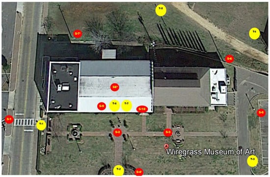
Figure 1.
A sample “Scan Position Layout Plan”. Red circles represent proposed scan locations, and yellow circles represent scan target locations.
Other aspects to be considered during TLS survey planning include the expected coverage of the survey (i.e., interior, exterior, or both), other data acquisition technologies and techniques that may be involved [14][35][52,72], the capture of color [1][40], and safety [21][59]. Column (b) in Table 1 shows the coverage (e.g., exterior façade only, interior façade only, or both exterior and interior) of the TLS scans for the studies included in the 58 selected publications.
Table 25. Information on data acquisition techniques and scan data processing of the HBIM projects in the included publications.
| (a) TLS Scanner Brands | (d) Control Reference | (e) Other RC Technologies Used for Data Acquisition | (f) Scan Processing Software | (g) # of Points Captured (million) | |||||||||||||||||
|---|---|---|---|---|---|---|---|---|---|---|---|---|---|---|---|---|---|---|---|---|---|
| Article | Country of Heritage Site | Year of Survey |
FARO | Leica | |||||||||||||||||
| [36] | [73] | Spain | 2019 | ✓ | Ext. and Int. | 7 | ✓ | ||||||||||||||
| [37] | [74] | Spain | 2016 | ✓ | ✓ | ||||||||||||||||
| [20] | [58] | Spain | 2021 | ✓ | ✓ | ✓ | |||||||||||||||
| [38] | [75] | Saudi Arabia | ✓ | Ext. and Int. | 100+ | ✓ | ✓ | ✓ | ✓ | ||||||||||||
| [18] | [56] | Italy | ✓ | ✓ | |||||||||||||||||
| [25] | [62] | Italy | ✓ | ✓ | ✓ | ||||||||||||||||
| [21] | [59] | Italy | 2020 | ✓ | Ext. and Int. | 65 | ✓ | ✓ | Handheld scanner | ||||||||||||
| [13] | [51] | Italy | ✓ | 213 | ✓ | ✓ | ✓ | ✓ | |||||||||||||
| [24] | [22] | Italy | 2021 | ✓ | Ext. and Int. | ✓ | ✓ | ✓ | ✓ | ✓ | ✓ | ||||||||||
| [28] | [65] | Italy | 2019 | ✓ | ✓ | ||||||||||||||||
| [39] a | [76] a | Italy | ✓ | ||||||||||||||||||
| [40] b | [77] b | Italy | ✓ | 182 | ✓ | ✓ | |||||||||||||||
| [41] | [78] | ||||||||||||||||||||
| [14] | [52] | Italy | 2021 | Ext. and Int. | 47 | ✓ | ✓ | ✓ | ✓ | ✓ | |||||||||||
| [27] | [64] | Italy | 2018 | ✓ | Ext. | 3 | ✓ | ✓ | 3D Zephyr | ||||||||||||
| [42] | [79] | Italy | 2020 | ✓ | ✓ | ✓ | ✓ | ||||||||||||||
| [35] | [72] | Brazil | 2016 | ✓ | ✓ | ✓ | |||||||||||||||
| [15] | [53] | Spain | 2019 | ✓ | Ext | 107 | ✓ | ✓ | ✓ | ✓ | ✓ | ✓ | ✓ | 182 | |||||||
| [6] | [45] | Spain | 2019 | ✓ | Ext. and Int. | 108 | ✓ | ✓ | ✓ | ✓ | ✓ | 214 | |||||||||
| [32] | [69] | Poland | 2017 | ✓ | Ext. and Int. | 7 | ✓ | ||||||||||||||
| [29] | [66] | Portugal | 2021 | ✓ | 3 | ✓ | Three-dimensional photo, Ground Penerating Radar (GPR); X-ray and SEM + EDX tests | 1345 | |||||||||||||
| [43] | [80] | Italy | 2018 | ✓ | Ext. | ✓ | ✓ | ✓ | |||||||||||||
| [44] | [81] | China | 2019 | ✓ | Ext. | 35 | ✓ | ✓ | ✓ | ✓ | Trimble Realwoks | ||||||||||
| [2] | [41] | Spain | 2020 | ✓ | Ext. | ✓ | ✓ | Thermal images | ✓ | PolyWorks | |||||||||||
| [45] | [14] | Egypt | 2019 | Z + F IMAGER | 160 | ✓ | ✓ | ||||||||||||||
| [16] | [54] | Portugal | 2019 | ✓ | Ext. and Int. | 95 | ✓ | ✓ | ✓ | ✓ | |||||||||||
| [10] | [49] | Italy | 2019 | ✓ | Ext. and Int. | 69 | ✓ | ✓ | ✓ | 1200 | |||||||||||
| [11] | [50] | Italy | 2019 | ✓ | Ext. and Int. | 64 | ✓ | 1014 | |||||||||||||
| [34] | [71] | Portugal | 2019 | ✓ | Ext. and Int. | 8 | ✓ | CloudCompare | |||||||||||||
| [3] a | [42] a | Spain | |||||||||||||||||||
| [46] b | [35] b | Spain | ✓ | Ext. and Int. | 15 | ✓ | ✓ | ✓ | ✓ | 103 | |||||||||||
| [47] | [82] | Spain | 2018 | ✓ | ✓ | ||||||||||||||||
| [1] c | [40] c | ||||||||||||||||||||
| [48] | [5] | ||||||||||||||||||||
| [49] | [83] | Italy | 2018 | ✓ | Ext. and Int. | 256 | ✓ | 3D photo, wearable laser scanner | |||||||||||||
| [26] | [63] | Vietnam | 2021 | ✓ | Ext. and Int. | 162 | ✓ | Trimble Realwoks | |||||||||||||
| [50] | [84] | Spain | 2018 | ✓ | Ext. and Int. | ||||||||||||||||
| [51] | [85] | Spain | ✓ | ||||||||||||||||||
| [7] | [46] | Slovakia | ✓ | Ext. and Int. | 141 | ✓ | ✓ | ✓ | ✓ | ||||||||||||
| [19] | [57] | Italy | ✓ | Ext. | 3 | ✓ | 3DF Zephyr | ||||||||||||||
| [33] | [70] | Italy | 2020 | ✓ | 3 | ✓ | ✓ | ||||||||||||||
| [52] | [6] | Spain | 2018 | ✓ | Ext. and Int. | 99 | ✓ | ✓ | ✓ | ||||||||||||
| [4] | [43] | ||||||||||||||||||||
| [31] | [68] | Portugal | 2019 | ✓ | Ext. and Int. | 144 | ✓ | ✓ | ✓ | ✓ | GPS | ✓ | ✓ | ||||||||
| [53] | [86] | Spain | 2016 | ✓ | Ext. and Int. | 27 | ✓ | ✓ | ✓ | GPS | ✓ | 3DReshaper | |||||||||
| [17] | [55] | France | 2015 | ✓ | Ext. and Int. | 40 | ✓ | ✓ | 3DReshaper | 839 | |||||||||||
| [54] | [87] | Italy | 2017 | ✓ | Ext. and Int. | 14 | |||||||||||||||
| [22] | [60] | Cyprus | Surphased | Ext. and Int. | 73 | ✓ | ✓ | JRC Reconstructor | 2080 | ||||||||||||
| [55] | [88] | Portugal | 10 | CloudCompare | |||||||||||||||||
| [56] | [89] | Poland | 2016 | Z + F IMAGER | Ext. and Int. | 36 | ✓ | ✓ | |||||||||||||
| [57] | [90] | China | 2021 | ✓ | Ext. and Int. | 25 | ✓ | ✓ | ✓ | ✓ | |||||||||||
| [58] | [91] | Italy | 2020 | Ext and Int | 24 | ✓ | ✓ | ✓ | |||||||||||||
| [23] | [61] | S. Korea | Handheld scanner | ✓ | |||||||||||||||||
| [59] | [92] | Algeria | 2020 | ✓ | Ext. and Int. | 188 | ✓ | ✓ | ✓ | ||||||||||||
4. Static TLS Devices
A total of 50 static TLS scanners from five different brands are explicitly mentioned in the selected publications, as shown in Figure 2. FARO® and Leica® dominate the list, supplying 24 and 20 of the scanners, respectively. Leica ScanStation C10 was one of the most widely adopted TLS scanners between 2015 and 2018 due to its high accuracy and long range. However, FARO Focus 3D series scanners started taking over in the late 2010s because of their high mobility and affordability. The FARO Focus Premium [60][93], Leica BLK360 [61][94], and Trimble X7 [62][95], as shown in Figure 3, are all considered to be the current state-of-the-art TLS scanners. All are lightweight, extremely fast, and have the capability of on-site registration. The brands of the TLS scanners used for HBIM projects in the included articles are shown in column (a) in Table 1.
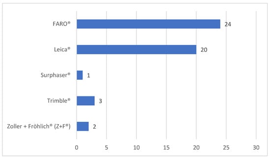
Figure 2.
Occurrences of TLS scanner brand names listed in the included publications.
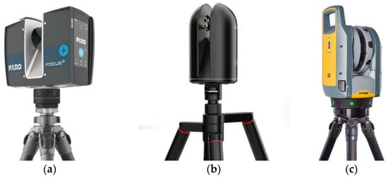
Figure 3.
Three of the latest state-of-the-art TLS scanners: (
5. TLS Survey
The scanners used for TLS surveys offer different options for scan resolution (Figure 4a). Scan resolution indicates the number of points captured per unit on a flat surface [20][58]. Scan resolution refers to the level of detail captured by the laser scanner during the scanning process and is an important consideration when selecting the appropriate settings for a particular scanning application. The scan resolution setting determines the density of points that the scanner will capture and create a point cloud from [32][69]. Several factors can impact the scan resolution, including the specification of the scanner, distance to the object, scan speed, reflectivity of the object, and environmental factors [32][69]. Choosing a scan resolution setting for TLS surveys depends on the specific application and the level of detail required. Depending on the site condition, the characteristics of the heritage, and time constraints, many HBIM practitioners choose to stay with the same scan resolution setting, normally an “intermedium level”, throughout the entire TLS survey for convenience and to save time. On the other hand, it is not unusual to use a combination of several resolution options to capture important facades at a high resolution and other areas at a medium or low resolution [52][6]. Maintaining field notes of the scan route to corroborate scan locations is essential for successful scan data postprocessing, as a project will rarely go as planned. Adjustments will be made, and more scans may be added to overcome occlusions or improve coverage and scan overlapping. All these changes to the original scan plan should be documented in the file notes. To improve the scan accuracy and help scan registration during postprocessing, reference points, such as GCPs or scan targets (e.g., spheres or checkboards) [7][14][46,52], are sometimes used, as shown in Table 1, Column (d). It is important to keep a record of the locations of these reference points in the field notes (Figure 4b).
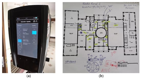
Figure 4. (a) Choosing scan resolution on a FARO Focus 3D S-350 scanner and (b) scanning field notes taken using a floor plan to track the locations of the scans.
6. Other RC Technologies Assisting TLS for Data Acquisition
Due to the complexity of the geometry of the built heritage and the limitations of the laser scanning technology, TLS is not a sufficient system for complete data acquisition. Therefore, it usually takes other technological tools and techniques to capture additional data about the heritage structure to supplement the TLS survey or to help improve the accuracy and coverage of the TLS survey [9][31][32][48,68,69]. These tools and techniques can be classified into the following groups:
See Column (e) in Table 1 for other RC technologies that were mentioned in the included publications.
6.1. SfM/Photogrammetry
TLS and photogrammetry can be integrated by exploiting the advantages of one over the other [27][64]. TLS is a more expensive technology in comparison with photogrammetric surveys, and higher knowledge is required to perform laser scans than to take photographs for 3D photoreconstructions [31][68]. On the other hand, photogrammetry is more cost-effective, more flexible, faster, and capable of collecting accurate and quality data for complex objects [9][48]. The benefit of integrating these two technologies is to take advantage of the TLS’s capability to acquire an accurate and dense point cloud and the flexibility of photogrammetry to operate even in exceptional conditions.
Combining TLS and photogrammetric techniques has proven to be the most effective way to record large and complex heritage sites in applications for documentation, structure assessment, texture mapping, feature extraction, etc. [12]. Twenty-three out of the fifty-eight articles included the capture of photogrammetric point clouds and combining them with TLS point clouds to fulfill the data acquisition task. In their research, de la Plata et al. [15][53] used a DSLR (digital single lens reflex) camera to generate high-density terrestrial photogrammetric point clouds of the interior surfaces of the buildings and TLS to capture exterior facades. Costantino, Pepe, and Restuccia [27][64] deployed a similar approach, using TLS to survey the external façade, a DLSR camera for inside, and a camera mounted on an unmanned aerial vehicle (UAV) for the upper part of the building. The integrated UAV with photogrammetric technology, as seen in Figure 5, offers practitioners the capacity to capture built heritage at higher elevations [63][96].
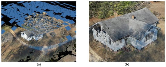
Figure 5.
UAV photogrammetry: (
a
) UAV photogrammetry schematic and (
b
) UAV photogrammetric point cloud.
6.2. Mobile Handheld Scanners
Two reviewed articles indicated the utilization of hand-held MLS scanners to supplement static TLS surveys. A mobile handheld scanner supported by photogrammetry or LiDAR technology can be used to capture some hard-to-reach small spaces or to record fine details. To scan the unsafe areas that were inaccessible by using their tripod-based FARO Focus 3D scanner, Banfi et al. [21][59] used a handheld Mobile Mapping System (MMS), a GeoSLAM ZEB-HORIZON, to perform the work. Nieto-Julian et al. [50][84] used a Leica ScanStation C10 scanner to capture walls, columns, ceilings, beams, and roofs alongside a handheld Artec MHT 3D optical scanner (OS) to record the complex column capitals of a historic building.
6.3. TS and GPS
TS and GPS are used to establish control points (CPs). CPs can be used to integrate point clouds acquired through different technologies (e.g., TLS and photogrammetry) or to check the quality and accuracy of the TLS scan data. Banfi et al. [21][59] used a Leica TPS1200 total station to setup eight CPs (four inside and four outside), and then used them to successfully combine the two point clouds captured with a TLS scanner and a handheld scanner.