Your browser does not fully support modern features. Please upgrade for a smoother experience.
Please note this is a comparison between Version 3 by Beatrix Zheng and Version 2 by Beatrix Zheng.
Greenhouse gas emission into the atmosphere is considered the main reason for the rise in Earth’s mean surface temperature. According to the Paris Agreement, to prevent the rise of the global average surface temperature beyond two degrees Celsius, global CO2 emissions must be cut substantially. While a transition to a net-zero emission scenario is envisioned by mid-century, carbon capture, utilization, and storage (CCUS) will play a crucial role in mitigating ongoing greenhouse gas emissions. Injection of CO2 into geological formations is a major pathway to enable large-scale storage.
- carbon utilization
- nanoparticle-stabilized foams
- geologic storage
1. Introduction
Global climate change is evidenced by disruptions in historical geographical and seasonal climate patterns. Persistent increases in the globally averaged surface air temperature are prominent features of these changes. The average temperature of Earth’s surface has increased by approximately one degree Celsius (1.8 degrees Fahrenheit) since the late 19th century [1]. These changes have accelerated rates of the mean sea level rise [2]. Human activities and the associated greenhouse gas (GHG) emissions, especially those emitted since the industrial revolution, are the main culprits of the ongoing changes in the Earth’s climate [3]. GHGs trap atmospheric heat [4] by absorbing infrared radiation from the sun [5]. These gases comprise a range of substances whose atmospheric concentrations considerably affect the global mean temperature [6]. According to the Fifth Intergovernmental Panel on Climate Change (IPCC) Assessment Report, the most critical GHGs based on their relative concentration and global warming potential comprise carbon dioxide (CO2), methane, nitrous oxide, chlorofluorocarbon-12 (CFC-12), hydrofluorocarbon-23 (HFC-23), sulfur hexafluoride, and nitrogen trifluoride [7]. CO2 accounts for approximately 76–79% of annual global GHG emissions [4][6][8]. The monthly average Mauna Loa concentration of CO2 for September of 2022 was reported as 415.95 ppm [9]. In 2020, CO2 emissions comprised 79% of the total anthropogenic GHG emissions in the US, of which 92% were due to fossil fuel combustion [10]. Despite a reduction in global energy demand and CO2 emissions by approximately 5.1% in 2020 due to the COVID-19 pandemic, the world experienced a fast economic recovery in 2021. A 5.9% increase in economic output in 2021 was associated with a 6% rise in CO2 emissions, making 2021 the most significant year-over-year increase in energy-related CO2 emissions [11]. Developing Asian countries, especially China and India, significantly contribute to increasing global CO2 emissions [12]. CO2 emissions must be substantially curtailed worldwide in all sectors of the economy to prevent further global temperature rises [13]. To this end, the Paris Agreement was negotiated in 2015 as a legally binding international treaty on climate change. This agreement was adopted by 196 Parties at the twenty-first session of the Conference of the Parties (COP) in December 2015 and entered into force on 4 November 2016 [14]. The main objective of the agreement is “[h]olding the increase in the global average temperature to well below 2 °C above pre-industrial levels and pursuing efforts to limit the temperature increase to 1.5 °C above pre-industrial levels …” (Paris Agreement, Art. 2(1)(a)) [15]. The implementation of the agreement requires significant economic and social transformations [15]. The energy sector is responsible for approximately three-quarters of GHG emissions. To achieve the Paris Agreement’s main objective, global CO2 emissions must be reduced to net zero by 2050 [16]. This reduction will necessitate a complete transformation of our means of energy production, transport, and consumption [17]. Climate-change-related problems and increasing scarcity of natural resources compel the world community to better manage energy demand and supply and transition to a sustainable energy system. Such a transformation requires a combination of energy efficiency, renewable energy use (solar, wind, biomass, hydroelectric, etc.), and carbon capture and storage [18].
Energy-related and industrial processes are responsible for approximately 80% of CO2 emissions [19]. According to the International Energy Agency (IEA), in 2020, about 78% of the world’s energy needs were met by fossil fuels (e.g., oil, natural gas, and coal) and the remaining 22% by nuclear, biofuel, hydro, and other sources [20]. These figures represent an increase of 3% in renewable energy use, with electricity generation from renewable sources having risen by 7% to account for approximately 29% of global electricity generation in 2020 [21]. A profound transformation from fossil-fuel-dependent to renewable-energy-based systems enhances energy efficiency. The International Renewable Energy Agency (IRENA) reports that renewables may account for up to two-thirds of the global primary energy supply by 2050 [22]. According to a report by the IEA, solar PV and wind make up two-thirds of the renewable energy growth. IRENA estimates that energy efficiency and renewable energy can, together, contribute 90% of the mitigation measures needed to reduce energy-related emissions. That means the energy-related CO2 emissions must fall by approximately 3.8% every year until 2050 to achieve levels 70% below today’s level and meet the goals of the Paris Agreement [19].
2. CCUS
Significant amounts of CO2 are produced and emitted into the atmosphere due to industrial processes [23]. Carbon capture, utilization, and storage (CUSCUS) is necessary to significantly reduce carbon dioxide emissions in the near term [24]. The CCUS supply chain comprises capture and compression of CO2, as well as transportation of CO2 to utilization and geologic storage sites [25]. It is predicted that carbon capture and storage will prevent about 32% of GHG emissions by 2050 [26].
The efficacy and adoption of utilization and sequestration of captured CO2 depend heavily on the availability of technology elements and favorable economic drivers. Leonzio et al. [27] use a mathematical model to assess the optimal supply chain of CCUS in the UK. Considering the net present value and the payback period of different utilization and storage options, they concluded that the geologic storage of captured CO2 is the most economical pathway [27].
The US Department of Energy (DOE) reports that the US has more than 2400 billion metric tons of CO2 storage capacity in saline aquifers, unminable coal seams, and oil and gas reservoirs [28]. A 2021 report by the IEA indicates that CCUS facilities around the globe have approximately 40 Mt of capture capacity each year [29]. However, the applications of CCUS technologies are complex. They depend on several factors, such as a detailed understanding of geology, geoengineering, geophysics, environmental impact, and related mathematical and computer science know-how [30].
2.1. Carbon Capture
CO2 separation and capture technologies for flue gas streams are commercially available [29]. Examples include direct air capture (DAC), precombustion, post combustion, and oxyfuel combustion [14].
2.1.1. Direct Air Capture
Unlike point-source capture from industrial sources, DAC refers to the capture of CO2 directly from the atmosphere and includes two main technologies: liquid and solid DAC. Liquid capture passes air through a solution, such as hydroxide, while solid DAC uses solid sorbent filters that chemically bind with carbon dioxide [31][32]. The world’s first and largest climate-positive DAC and storage plant, Orca, launched in September 2021 in Hellisheidi, Iceland. Orca is located near the Hellisheiði geothermal power plant, runs entirely on renewable energy, and has around 4000 tons of CO2 capture capacity yearly [33]. According to the IEA, there are 19 DAC plants currently operating worldwide, which capture more than 0.01 Mt of CO2 per year. An additional 1 Mt of annual CO2 capture capacity is in an advanced development stage in the US [31].
2.1.2. Precombustion Capture
The precombustion method refers to capturing and removing CO2 before combustion is completed [34]. Precombustion CO2 capture is usually associated with high CO2 concentrations (15–60% by volume) and high-pressure and high-temperature process streams [35][36]. In precombustion, fossil fuels are converted to syngas (a mixture of CO and H2). Syngas is typically produced by adding either steam (i.e., steam reforming) or oxygen (i.e., partial oxidation or gasification) to the primary fuel. In both cases, the process is followed by a water–gas shift reaction [37]. This water–gas shift reaction converts CO and water to CO2 and H2-rich gas. CO2 can be separated, and H2-rich fuel can be combusted [34].
2.1.3. Post-Combustion Capture
Post-combustion capture refers to removing CO2 from the product flue gas stream. CO2 may be removed from hydrogen-rich gases using a physical solvent [12]. The main adsorbents for the post-combustion process include activated carbon, metallic oxides, alumina, and zeolites. Regeneration of adsorbents requires heat (temperature swing adsorption) or a reduction in pressure (pressure swing adsorption) [38][39]. The leading post-combustion technologies rely on adsorption, physical and chemical absorption, cryogenics separation, and membranes [38][40]. Aqueous amine solutions (chemical absorption) are the most mature technology for removing CO2 from natural gas. Recent improvements in polymeric membrane technology have enabled CO2 capture from coal-fired power plants and related combustion sources [41].
Dissolution of CO2 requires high pressures, with CO2 released once more as the pressure drops. The precombustion approach does not require heat for solvent regeneration, and the removed CO2 can be released above atmospheric pressure. Therefore, precombustion capture and compression of CO2 may be twice as efficient as post combustion. Disadvantages of precombustion capture include a loss of the potential for power generation due to the removal of CO that may otherwise be burned in the turbine to generate power. Additionally, natural gas or syngas (conventional) turbines are more efficient than hydrogen-burning gas turbines [42].
2.1.4. Oxyfuel Combustion
Oxyfuel combustion technologies are among the leading technologies for CCUS. The main principle of oxyfuel combustion is the burning of the fuel using pure oxygen instead of air, which allows for improved control over flame temperature and recycling of a portion of the flue gas back to the furnace. The advantage of the oxyfuel method is that it generates a highly concentrated CO2 flue stream, which eases the post-separation process [43], and it only requires CO2 in most combustion systems [44]. The optimal oxygen concentration for the oxyfuel process is approximately 97% oxygen purity [45]. Oxyfuel combustion in power generation comprises four units: an air separation unit (oxygen production), a gas turbine or boiler (heat generation), a flue gas processing unit (quality control system), and a CO2 processing unit (CO2 purification, transport, and storage) [43].
The use of oxygen instead of air in oxyfuel combustion results in more efficient combustion [46]; it decreases fuel consumption and helps to obtain more than 80% volume concentrated CO2 stream, which makes purification easier through mechanical separation [44][47].
2.2. Utilization
CO2 is often considered a waste product in the context of flue gases. Recent crises have led to the exploration of the use of CO2 in various applications, which has turned CO2 into a potentially valuable product [48]. Through carboxylation reactions, CO2 can be employed to produce various chemicals [49]. Moreover, CO2 can be directly applied for compound extraction, e.g., in enhanced oil recovery (EOR), the food industry, and dry cleaning [49]. CO2 can also be incorporated into construction and building materials [48]. This research classifies CO2 utilization technologies into (i) CO2 to products and (ii) geological categories [50].
2.2.1. CO2 to Products
CO2 may be used as raw material in products such as beverages and food, inorganic chemicals, fertilizers, fuels, agricultural goods, building materials, etc. [50]. Methanol, formic acid, urea, cyclic carbonates, and salicylic acid are the most common products that can be obtained via CO2 [51]. The United States National Academy of Sciences (NAS) categorizes CO2-based products into long-lived and shorter-lived products. Long-lived CO2-based products are durable, with more than 100 years of carbon storage capacity. In contrast, shorter-lived products may be recycled as part of the circular carbon economy over a shorter time span [52].
CO2 to Methanol
The idea of upgrading CO and CO2 to produce methanol dates back to the 1970s [53]. Large-scale methanol production is possible through the following reactions [54][55]:
CO+2H2↔CO3O
CO2+H2↔CO+H2O
CO2+3H2↔CO3OH+H2O
The first reaction is methanol synthesis from CO, the second is a reverse water–gas reaction, and the third is methanol synthesis. Recently, Nobel Prize winner George A. Olah advocated for a term called “methanol economy”, in which captured CO2 from the atmosphere and H2 produced from renewable energy sources can be used to produce methanol and used as fuel and raw material for synthetic hydrocarbons [56]. Although hydrogen is considered a clean energy source and plays an essential role in the chemical industry, it is not easy to store and transport, restricting its wide-scale adoption as an energy carrier. On the other hand, methanol is an excellent H2 source with low toxicity. Low-chain alcohols are considered an alternative, more accessible pathway to transport and store hydrogen [57]. Methanol may be mixed with conventional gasoline without requiring technical modifications of vehicles [58]. Around 90% of methanol is produced from natural gas [59].
CO2 to Formic Acid and Urea
Urea is an essential product that can be obtained from CO2. Urea is the most widely used synthetic nitrogen fertilizer and accounts for about 70% of worldwide fertilizer usage [60]. Urea has a high nitrogen content (up to 46%) and is most commonly produced through the following reactions [51]:
N2+3H2→2NH3
CO2+2NH3→NH2CONH2+H2O
Urea production requires fossil fuels, which leads to greenhouse gas emissions. In urea production, natural gas is purified and converted to syngas in a reforming unit [61]. Agriculture and other land use contribute significantly to GHG emissions, according to the IPCC. These activities accounted for about 23% of anthropogenic CO2 emissions between 2007 and 2016 [16]. However, the contribution of agricultural activities to the global carbon cycle is complex. Nitrogen-based synthetic fertilizers can change forest carbon distribution [62]. Results from a worldwide meta-analysis from 1998 to 2021 proved that nitrogen fertilizers significantly decrease soil bacterial and fungal diversity, affecting the soil’s important carbon content [63]. Adding nitrogen to soil also plays a critical role in soil respiration. Soil respiration is also temperature-sensitive, and increasing average global temperature and increasing nitrogen-based fertilizer usage can significantly affect the cycle [64].
Formic acid is also an essential and often-used commodity in the chemical industry. It can be obtained in various ways, including the CO2 hydrogenation reaction shown below to synthesize formic acid using CO2 as raw material [65]. The worldwide production capacity of formic acid is approximately 950 thousand tons per year [66].
CO2+H2→HCOOH
Life cycle assessment of several CO2-based chemicals shows that CO2-based production of formic acid reduces the environmental impact significantly [51][67]. Most of the produced formic acid is used in silage for animal feeds, as tanning and dyeing agents in the textile industry, as a coagulating agent for latex rubber production, and as a food preservative [68].
2.2.2. Biological Sequestration
Photosynthesis is the conversion of solar energy into chemical energy by green plants and certain other organisms. Carbohydrate molecules synthesized from water and CO2 can store this chemical energy [69]. The overall oxygenic photosynthesis reaction can be expressed as [70]:
CO
2
+ H
2
O → (CH
2
O) + H
2
O + O
2
A single mature tree can absorb about 50 pounds of carbon dioxide annually. This absorption rate means that approximately 200 billion trees are needed to remove the CO2 emitted in the US annually [71]. However, some microorganisms and microalgae have higher carbon fixation rates than terrestrial plants [72]. Generally, there are two main biological processes for biological carbon sequestration: (i) biomass for energy generation with CO2 capture and (ii) the photosynthetic systems of microorganisms [73]. Microalgae can transport bicarbonate into their cells with as high as 90% efficiency and harvest 100% of the biomass [74].
2.2.3. Geologic Utilization
Geological utilization of CO2 mainly comprises applications for subsurface energy extraction, including enhanced oil recovery (CO2-EOR), hydrocarbon production from residual oil zones (ROZs), coalbed methane, and CO2-enhanced shale gas recovery [50].
CO2-EOR
The most substantial use of CO2 is in enhanced oil recovery [48]. During the life of a petroleum reservoir, the fluids are typically produced initially by a natural drive mechanism such as a gas cap or dissolved gas expansion and saline water influx. This production is possible until the reservoir pressure and oil production rates decline. At that point, a secondary recovery phase, referred to as improved oil recovery (IOR), begins, which is most commonly achieved by injecting water [75]. Under favorable conditions, primary recovery and IOR may produce up to one-third of the oil that was originally in place. The remaining oil, estimated to be more than 5000 billion barrels worldwide, may be accessed and produced using EOR techniques such as “next generation” CO2-EOR [76]. Recovery techniques that are applied after a primary and a secondary recovery phase are referred to as tertiary recovery, and EOR often falls in that category, even though CO2 EOR may be applied during the secondary recovery phase, such as in the North Cross field in West Texas [75][77]. CO2-EOR has been studied and applied in several experimental projects since the 1950s [78]. According to a recent report from the IEA, about 375 active EOR projects supplied about 2% of the global oil supply in 2017, of which 166 were CO2-EOR projects [79].
Most reservoirs under CO2-EOR projects are deep enough and are pressurized beyond the minimum miscibility pressure (MMP) of CO2 [80]. For reference, the Yates field in West Texas is an example of an immiscible CO2 flood [81]. Main CO2 EOR mechanisms include oil viscosity reduction, the oil-swelling effect, interfacial tension reduction, light-hydrocarbon extraction, and miscible displacement if the reservoir pressure exceeds its MMP [78]. The density of supercritical CO2 approaches that of a liquid, but its viscosity remains quite low [80]. CO2 flooding approaches include CO2 huff-n-puff, continuous CO2 flooding, and CO2 water-alternating-gas (CO2-WAG) methods [82]. Supercritical CO2 flooding has been demonstrated to improve the oil recovery factor in unconventional reservoirs [83].
Residual Oil Zones
A ROZ is defined as residual oil with respect to waterflood below the oil-water contact (OWC) of a reservoir. ROZs are similar to classical reservoirs after a mature waterflooding process, the difference being that ROZs have essentially been flooded by natural aquifers [84]. Although primary or secondary oil production from ROZs is often not economical, CO2 flooding is a viable recovery technique [85]. Three primary types of ROZs are identified [86]: (i) One type of ROZ happens because of a regional tilt of a basin. This type occurs when an existing hydrocarbon reservoir (stratigraphic trap) is subjected to a tectonically induced tilt [87]. (ii) Another type of ROZ is due to water invasion of areas that are subject to migration of trapped oil through breached seals. (iii) The final type of ROZ is similar to type one, the difference being that they are a result of changes in hydrodynamic conditions of groundwater [86][87]. CO2-EOR is an increasingly used technique for oil production from ROZs, especially in the Permian Basin [86][88][89]. ROZs are also considered potential targets for long-term geologic carbon storage [90]. CO2 storage in ROZs is mainly impacted by reservoir heterogeneity and injection strategies [91]. For example, in the case of vertical CO2 injectors, high ratios of WAG always result in higher retention fractions; however, this process results in a reduction in cumulative CO2 injection. Therefore, different strategies may be applied depending on whether the intention is to maximize oil production or enhance storage [91]. Since EOR contributes to anthropogenic GHG emissions, whether CO2-EOR will result in a net CO2 reduction is an ongoing discussion. Comparisons indicate that one barrel of oil recovered by CO2-EOR has a lower CO2 emission than one barrel produced through primary recovery or IOR [48].
Enhanced Gas Recovery in Coalbed Methane
Coalbed methane (CBM) is considered an unconventional gas reservoir. Methane in coalbeds is stored on the internal surfaces of microporous coal as sorbed gas near liquid densities [92]. CBM is also called coal seam methane, coal seam gas, and coal seam natural gas and may contain trace amounts of other fluids [93]. CBM can be a significant hazard for coal mine development, with the potential for explosions ignited by different sources during mining operations and causing severe causalities [94]. Since the 1970s, CBM has been successfully developed into a commercially and economically sustainable product, primarily in the United States and Canada [95]. Conventional CBM recovery is based on the pressure depletion strategy of the reservoir. Removing water from the reservoir reduces the pressure, and some gas desorbs from the coal [92]. The main problems associated with CBM development are the low permeability of coal beds and high methane adsorption. Therefore, CBM development techniques involve injecting various materials, including water, CO2, and steam [96]. Injecting supercritical CO2 in the coal seam can enhance methane recovery considerably [97]. CO2-enhanced coalbed methane (ECBM) is based on competitive sorption between CO2 and methane on coal. CO2 has more significant adsorption than methane, resulting in the desorption of existing methane when injecting CO2 into a coal bed [98].
2.3. Storage
The captured CO2 must be permanently stored to mitigate the adverse effects on the global climate [99]. Long-term CO2 storage may be possible through underground sequestration in sedimentary formations and carbon mineralization [100]. Between the two, CO2 sequestration in the subsurface is a mature technique and may be applied to different sedimentary formations [99]. Geological formations can store massive amounts of CO2. Examples include oil and gas reservoirs, deep saline aquifers, silicate formations, and unminable coal streams [48]. It is estimated that up to 11,000 Gt of CO2 may be stored in subsurface formations. In contrast, the 2022 global energy-related CO2 emissions reached 36.8 Gt [101].
Saline aquifers are brine-saturated layers of porous rock and are more extensive than oil-and-gas-bearing rocks or coal streams [102]. Saline aquifers are estimated to hold most of the overall geologic storage potential [103][104][105]. The estimations of this potential storage fall within a wide range due to differences in assumptions such as density, characteristics of aquifers, technological and economic constraints, and whether CO2 remains as a separate fluid phase or dissolves in brine. The upper limit of the storage capacity of saline aquifers is uncertain due to insufficient geologic data [40]. Even though aquifers may be located near stationary CO2 emission sites [106][107], their depth and high concentrations of dissolved salt contents make saline aquifers economically suboptimal. Hepple and Benson [108] concluded that 90–99% of injected CO2 is expected to remain effectively trapped over thousands of years. Expertise related to transportation and injection aspects of geologic CO2 storage is readily available in the EOR community [109]. Although there is no universally accepted definition of coal minability, some coal mines are accepted as qualitatively and economically unminable. The reasons may include the mines being too deep, having poor quality, and land use restrictions [110]. ECBM processes in unminable coal seams can permanently store CO2. Although unamenable coal seams have a smaller CO2 storage capacity than other geological formations, it is estimated that about 3 to 200 Gt of CO2 can be stored globally in unminable coal seams [97].
Several industrial-scale CO2 storage projects in saline aquifers are underway [105]. CO2 injection in a saline aquifer has been operated in Canada to decrease H2S flaring from sour gas wells [105]. The Sleipner project in the Norwegian part of the North Sea is considered the first commercial CO2 storage project in deep aquifers. Injection in Sleipner started in October 1996, with 1 Mt of CO2 injected yearly [111]. The In Salah project in Algeria is another example of CO2 from the production of natural gas sequestered in the subsurface. This project is estimated to have saved the equivalent of 1.2 million tons of greenhouse emissions every year since 2004 [112]. A similar CO2 injection project is implemented offshore in Norway in the Snøhvit field. The injection started in 2008, and the cumulative CO2 injection is estimated to be equivalent to 2% of the total emissions of Norway over 30 years [113]. The Weyburn project in Canada is a large-scale CO2-EOR storage project estimated to store 50 million tons of CO2 over its lifetime [114]. CO2 injection in saline aquifers is simpler than CO2-EOR, since aquifers contain only brine. Furthermore, rates of injection into saline aquifers may be kept high while bottomhole pressures are kept relatively low. In general, there are three main CO2 storage mechanisms, namely geochemical, geological, and hydrodynamic trapping [115] (see Figure 21). Amongst various trapping mechanisms, the following are considered the most significant in saline aquifers: structural, residual, solubility, and mineral trapping [107].
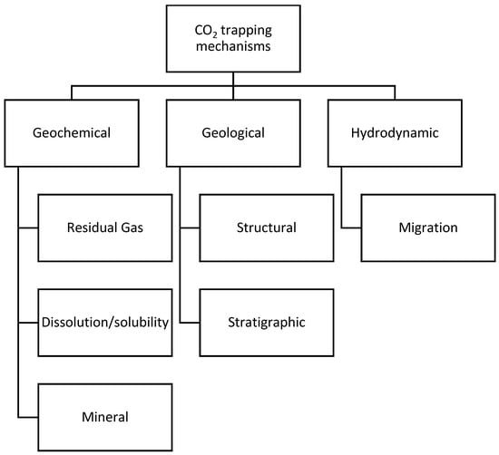
Figure 21. CO2 trapping mechanisms.
Mineral trapping is a permanent storage mechanism in saline aquifers. Injecting a slug of brine after the completion of CO2 injection may accelerate CO2 dissolution [116]. Dissolved CO2 reacts with the minerals in host formations and creates stable minerals over geological timeframes [117][118]. Solubility also plays a vital role in geological storage, depending on temperature, pressure, and salt content [119][120].
Since the goal is permanent geologic storage of CO2, safety and storage reliability over the long term are paramount. As such, one must assess potential risks associated with the formation and activation of fractures [48]. Hazards include possible leakage of stored fluids through the caprock, degraded well cement, and transmissive faults and fractures [121]. Minimization of CO2 mobility by mineralizing it into some form of the carbonate, such as limestone or magnesite, will reduce the amount of free and mobile CO2. However, mineralization may occur on the order of the geological timescale. Research into improving and accelerating the mineralization process is ongoing in the community [122].
References
- Wolff, E.; Fung, I.; Hoskins, B.; Mitchell, J.F.B.; Palmer, T.; Santer, B.; Shepherd, J.; Shine, K.; Solomon, S.; Trenberth, K.; et al. Climate Change: Evidence & Causes—Update 2020. In The Royal Society and the U.S. National Academy of Sciences; The National Academies Press: Washington, DC, USA, 2020.
- National Academy of Sciences. Climate Change: Evidence and Causes: Update 2020; The National Academies Press: Washington, DC, USA, 2020.
- US EPA. Causes of Climate Change. . 19 August 2022. Available online: https://www.epa.gov/climatechange-science/causes-climate-change (accessed on 29 March 2023).
- US EPA. Overview of Greenhouse Gases. 16 May 2022. Available online: https://www.epa.gov/ghgemissions/overview-greenhouse-gases (accessed on 29 March 2023).
- EIA. Greenhouse Gases—U.S. Energy Information Administration (EIA). 2021. Available online: https://www.eia.gov/energyexplained/energy-and-the-environment/greenhouse-gases.php (accessed on 29 March 2023).
- C2ES. Global Anthropogenic GHG Emissions by Gas. 2005. Available online: https://www.c2es.org/content/international-emissions/ (accessed on 29 March 2023).
- Pachauri, R.K.; Mayer, L.; Intergovernmental Panel on Climate Change (Eds.) Climate change 2014: Synthesis report. In Intergovernmental Panel on Climate Change; IPCC: Geneva, Switzerland, 2015.
- Rahman, F.A.; Aziz, M.M.A.; Saidur, R.; Bakar, W.A.W.A.; Hainin, M.R.; Putrajaya, R.; Hassan, N.A. Pollution to solution: Capture and sequestration of carbon dioxide (CO2) and its utilization as a renewable energy source for a sustainable future. Renew. Sustain. Energy Rev. 2017, 71, 112–126.
- NOAA Global Monitoring Laboratories. Trends in Atmospheric Carbon Dioxide. Carbon Cycle Greenhouse Gases. 22 October 2022. Available online: https://gml.noaa.gov/ccgg/trends/ (accessed on 29 March 2023).
- U.S. Energy Information Administration (EIA). Where Greenhouse Gases Come from, Energy and the Environment Explained. 24 June 2022. Available online: https://www.eia.gov/energyexplained/energy-and-the-environment/where-greenhouse-gases-come-from.php (accessed on 29 March 2023).
- Global Energy Review: CO2 Emissions in 2021. 2021. Available online: https://www.iea.org/reports/global-energy-review-co2-emissions-in-2021-2 (accessed on 29 March 2023).
- Gür, T.M. Carbon Dioxide Emissions, Capture, Storage and Utilization: Review of Materials, Processes and Technologies. Prog. Energy Combust. Sci. 2022, 89, 100965.
- Yan, J.; Zhang, Z. Carbon Capture, Utilization and Storage (CCUS). Appl. Energy 2019, 235, 1289–1299.
- UNFCCC. The Paris Agreement|UNFCCC. 2020. Available online: https://unfccc.int/process-and-meetings/the-paris-agreement/the-paris-agreement (accessed on 29 March 2023).
- Paris Agreement. Report of the Conference of the Parties to the United Nations Framework Convention on Climate Change, (21st Session, 2015: Paris). Retrieved December, HeinOnline, 2015.
- IPCC. Climate Change and Land: An IPCC Special Report on Climate Change, Desertification, Land Degradation, Sustainable Land Management, Food Security, and Greenhouse Gas Fluxes in Terrestrial Ecosystems; IPCC: Ginevra, Switzerland, 2019.
- IEA. Net Zero by 2050—A Roadmap for the Global Energy Sector; National Academies Press: Washington, DC, USA, 2021; p. 224.
- Solomon, B.D.; Krishna, K. The coming sustainable energy transition: History, strategies, and outlook. Energy Policy 2011, 39, 7422–7431.
- IRENA. Global Renewables Outlook: Energy Transformation 2050; IRENA: Bonn, Germany, 2020.
- IEA. Key World Energy Statistics 2021; International Energy Agency: Paris, France, 2021.
- IEA. Global Energy Review 2021; International Energy Agency: Paris, France, 2021.
- IRENA. Power System Flexibility for the Energy Transition, Part 1: Overview for Policy Makers; International Renewable Energy Agency: Bonn, Germany, 2018; Available online: https://www.irena.org/-/media/Files/IRENA/Agency/Publication/2018/Nov/IRENA_Power_system_flexibility_1_2018.pdf (accessed on 29 March 2023).
- Wilberforce, T.; Baroutaji, A.; Soudan, B.; Al-Alami, A.H.; Olabi, A.G. Outlook of carbon capture technology and challenges. Sci. Total Environ. 2019, 657, 56–72.
- Yang, L.; Zhang, X.; McAlinden, K.J. The effect of trust on people’s acceptance of CCS (carbon capture and storage) technologies: Evidence from a survey in the People’s Republic of China. Energy 2016, 96, 69–79.
- Hasan, M.F.; First, E.L.; Boukouvala, F.; Floudas, C.A. A multi-scale framework for CO2 capture, utilization, and sequestration: CCUS and CCU. Comput. Chem. Eng. 2015, 81, 2–21.
- IEA. Energy Technology Perspectives 2017: Catalysing Energy Technology Transformations; OECD: Paris, France, 2017.
- Leonzio, G.; Bogle, D.; Foscolo, P.U.; Zondervan, E. Optimization of CCUS supply chains in the UK: A strategic role for emissions reduction. Chem. Eng. Res. Des. 2020, 155, 211–228.
- DOE. Carbon Storage Atlas: Fifth Edition. 2015. Available online: https://www.netl.doe.gov/sites/default/files/2018-10/ATLAS-V-2015.pdf (accessed on 29 March 2023).
- IEA. Carbon Capture, Utilisation and Storage—Fuels & Technologies. IEA. September 2021. Available online: https://www.iea.org/fuels-and-technologies/carbon-capture-utilisation-and-storage (accessed on 29 March 2023).
- Liu, H.J.; Were, P.; Li, Q.; Gou, Y.; Hou, Z. Worldwide Status of CCUS Technologies and Their Development and Challenges in China. Geofluids 2017, 2017.
- IEA. Direct Air Capture—Analysis. 2021. Available online: https://www.iea.org/reports/direct-air-capture (accessed on 29 March 2023).
- MacDowell, N.; Florin, N.; Buchard, A.; Hallett, J.; Galindo, A.; Jackson, G.; Adjiman, C.S.; Williams, C.K.; Shah, N.; Fennell, P. An overview of CO2 capture technologies. Energy Environ. Sci. 2010, 3, 1645–1669.
- Climate Works. Orca Is Climeworks’ New Large-Scale Carbon Dioxide Removal Plant. 2021. Available online: https://climeworks.com/roadmap/orca (accessed on 29 March 2023).
- DOE. Pre-Combustion Carbon Capture Research. Available online: https://www.energy.gov/fecm/science-innovation/carbon-capture-and-storage-research/carbon-capture-rd/pre-combustion-carbon (accessed on 29 March 2023).
- Theo, W.L.; Lim, J.S.; Hashim, H.; Mustaffa, A.A.; Ho, W.S. Review of pre-combustion capture and ionic liquid in carbon capture and storage. Appl. Energy 2016, 183, 1633–1663.
- Wall, T.F. Combustion processes for carbon capture. Proc. Combust. Inst. 2007, 31, 31–47.
- Jansen, D.; Gazzani, M.; Manzolini, G.; van Dijk, E.; Carbo, M. Pre-combustion CO2 capture. Int. J. Greenh. Gas Control 2015, 40, 167–187.
- Wang, M.; Lawal, A.; Stephenson, P.; Sidders, J.; Ramshaw, C. Post-combustion CO2 capture with chemical absorption: A state-of-the-art review. Chem. Eng. Res. Des. 2011, 89, 1609–1624.
- Zhao, Z.; Cui, X.; Ma, J.; Li, R. Adsorption of carbon dioxide on alkali-modified zeolite 13X adsorbents. Int. J. Greenh. Gas Control 2007, 1, 355–359.
- IPCC. Carbon Dioxide Capture and Storage. IPCC. 2005. Available online: https://www.ipcc.ch/report/carbon-dioxide-capture-and-storage/ (accessed on 29 March 2023).
- Bui, M.; Adjiman, C.S.; Bardow, A.; Anthony, E.J.; Boston, A.; Brown, S.; Fennell, P.S.; Fuss, S.; Galindo, A.; Hackett, L.A.; et al. Carbon capture and storage (CCS): The way forward. Energy Environ. Sci. 2018, 11, 1062–1176.
- Gibbins, J.; Chalmers, H. Carbon capture and storage. Energy Policy 2008, 36, 4317–4322.
- Stanger, R.; Wall, T.; Spörl, R.; Paneru, M.; Grathwohl, S.; Weidmann, M.; Scheffknecht, G.; McDonald, D.; Myöhänen, K.; Ritvanen, J.; et al. Oxyfuel combustion for CO2 capture in power plants. Int. J. Greenh. Gas Control 2015, 40, 55–125.
- Koohestanian, E.; Shahraki, F. Review on principles, recent progress, and future challenges for oxy-fuel combustion CO2 capture using compression and purification unit. J. Environ. Chem. Eng. 2021, 9, 105777.
- Soundararajan, R.; Gundersen, T.; Ditaranto, M. Oxy-combustion coal based power plants: Study of operating pressure, oxygen purity and downstream purification parameters. Chem. Eng. Trans. 2014, 39, 229–234.
- Hong, J.; Chaudhry, G.; Brisson, J.; Field, R.; Gazzino, M.; Ghoniem, A.F. Analysis of oxy-fuel combustion power cycle utilizing a pressurized coal combustor. Energy 2009, 34, 1332–1340.
- Darde, A.; Prabhakar, R.; Tranier, J.-P.; Perrin, N. Air separation and flue gas compression and purification units for oxy-coal combustion systems. Energy Procedia 2009, 1, 527–534.
- Smit, B.; Park, A.-H.A.; Gadikota, G. The Grand Challenges in Carbon Capture, Utilization, and Storage. Front. Energy Res. 2014, 2.
- Baena-Moreno, F.M.; Rodríguez-Galán, M.; Vega, F.; Alonso-Fariñas, B.; Vilches Arenas, L.F.; Navarrete, B. Carbon capture and utilization technologies: A literature review and recent advances. Energy Sources Part A Recovery Util. Environ. Eff. 2019, 41, 1403–1433.
- Coddington, K.; Gellici, J.; Hilton, R.; Wade, S.; Ali, S.; Berger, A.; Carr, M.; Eames, F.; Godec, M.; Harju, J.; et al. CO2 BUILDING BLOCKS Assessing CO2 Utilization Options. National Coal Council. 2016. Available online: https://www.nationalcoalcouncil.org/studies/2016/NCC-CO2-Building-Block-FINAL-Report.pdf (accessed on 29 March 2023).
- Zhang, Z.; Pan, S.-Y.; Li, H.; Cai, J.; Olabi, A.G.; Anthony, E.J.; Manovic, V. Recent advances in carbon dioxide utilization. Renew. Sustain. Energy Rev. 2020, 125, 109799.
- National Academies of Sciences, Engineering, and Medicine. Carbon Dioxide Utilization Markets and Infrastructure: Status and Opportunities: A First Report; National Academies Press: Washington, DC, USA, 2022; p. 26703.
- Steinberg, M. Synthetic carbonaceous fuels and feedstocks from oxides of carbon and nuclear power. Fuel 1978, 57, 460–468.
- Meunier, N.; Chauvy, R.; Mouhoubi, S.; Thomas, D.; De Weireld, G. Alternative production of methanol from industrial CO2. Renew. Energy 2020, 146, 1192–1203.
- Pontzen, F.; Liebner, W.; Gronemann, V.; Rothaemel, M.; Ahlers, B. CO2-based methanol and DME—Efficient technologies for industrial scale production. Catal. Today 2011, 171, 242–250.
- Olah, G.A. Beyond Oil and Gas: The Methanol Economy. Angew. Chem. Int. Ed. 2005, 44, 2636–2639.
- Lü, Y.-J.; Yan, W.-J.; Hu, S.-H.; Wang, B.-W. Hydrogen production by methanol decomposition using gliding arc gas discharge. J. Fuel Chem. Technol. 2012, 40, 698–706.
- Dalena, F.; Senatore, A.; Marino, A.; Gordano, A.; Basile, M.; Basile, A. Methanol Production and Applications: An Overview. In Methanol; Elsevier: Amsterdam, The Netherlands, 2018; pp. 3–28.
- Bertau, M.; Offermanns, H.; Plass, L.; Schmidt, F.; Wernicke, H.-J. (Eds.) Methanol: The Basic Chemical and Energy Feedstock of the Future; Springer: Berlin/Heidelberg, Germany, 2014.
- Driver, J.G.; Owen, R.E.; Makanyire, T.; Lake, J.A.; McGregor, J.; Styring, P. Blue Urea: Fertilizer With Reduced Environmental Impact. Front. Energy Res. 2019, 7, 88.
- Koohestanian, E.; Sadeghi, J.; Mohebbi-Kalhori, D.; Shahraki, F.; Samimi, A. A novel process for CO2 capture from the flue gases to produce urea and ammonia. Energy 2018, 144, 279–285.
- Li, W.; Shi, Y.; Zhu, D.; Wang, W.; Liu, H.; Li, J.; Shi, N.; Ma, L.; Fu, S. Fine root biomass and morphology in a temperate forest are influenced more by the nitrogen treatment approach than the rate. Ecol. Indic. 2021, 130, 108031.
- Yang, Y.; Chen, X.; Liu, L.; Li, T.; Dou, Y.; Qiao, J.; Wang, Y.; An, S.; Chang, S.X. Nitrogen fertilization weakens the linkage between soil carbon and microbial diversity: A global meta-analysis. Glob. Chang. Biol. 2022, 28, 6446–6461.
- Yang, Y.; Li, T.; Pokharel, P.; Liu, L.; Qiao, J.; Wang, Y.; An, S.; Chang, S.X. Global effects on soil respiration and its temperature sensitivity depend on nitrogen addition rate. Soil Biol. Biochem. 2022, 174, 108814.
- Hao, C.; Wang, S.; Li, M.; Kang, L.; Ma, X. Hydrogenation of CO2 to formic acid on supported ruthenium catalysts. Catal. Today 2011, 160, 184–190.
- Bulushev, D.A.; Ross, J.R.H. Towards Sustainable Production of Formic Acid. ChemSusChem 2018, 11, 821–836.
- Sternberg, A.; Jens, C.M.; Bardow, A. Life cycle assessment of CO2-based C1-chemicals. Green Chem. 2017, 19, 2244–2259.
- Leitner, W. Carbon Dioxide as a Raw Material: The Synthesis of Formic Acid and Its Derivatives from CO2. Angew. Chem. Int. Ed. 1995, 34, 2207–2221.
- Goli, A.; Shamiri, A.; Talaiekhozani, A.; Eshtiaghi, N.; Aghamohammadi, N.; Aroua, M.K. An overview of biological processes and their potential for CO2 capture. J. Environ. Manag. 2016, 183, 41–58.
- Bowyer, J.R.; Leegood, R.C.; Dey, P.M.; Harborne, J.B. Plant Biochemistry; Academic Press: Cambridge, MA, USA, 1997.
- Moseman, A.; Harvey, C. How Many New Trees Would We Need to Offset Our Carbon Emissions? MIT Climate Portal. 2022. Available online: https://climate.mit.edu/ask-mit/how-many-new-trees-would-we-need-offset-our-carbon-emissions (accessed on 29 March 2023).
- Ramanan, R.; Kannan, K.; Deshkar, A.; Yadav, R.; Chakrabarti, T. Enhanced algal CO2 sequestration through calcite deposition by Chlorella sp. And Spirulina platensis in a mini-raceway pond. Bioresour. Technol. 2010, 101, 2616–2622.
- Surampalli, R.Y.; Zhang, T.C.; Tyagi, R.D.; Naidu, R.; Gurjar, B.R.; Ojha, C.S.P.; Yan, S.; Brar, S.K.; Ramakrishnan, A.; Kao, C.M. (Eds.) Carbon Capture and Storage: Physical, Chemical, and Biological Methods; American Society of Civil Engineers: Reston, VA, USA, 2015.
- Sayre, R. Microalgae: The Potential for Carbon Capture. Bioscience 2010, 60, 722–727.
- Núñez-López, V.; Moskal, E. Potential of CO2-EOR for Near-Term Decarbonization. Front. Clim. 2019, 1, 5.
- Kuuskraa, V.A.; Godec, M.L.; Dipietro, P. CO2 Utilization from “Next Generation” CO2 Enhanced Oil Recovery Technology. Energy Procedia 2013, 37, 6854–6866.
- Aryana, S.A.; Barclay, C.; Liu, S. North cross Devonian unit-a mature continuous CO2 flood beyond 200% HCPV injection. In Proceedings of the SPE Annual Technical Conference and Exhibition SPE, Amsterdam, The Netherlands, 27–29 October 2014.
- Cao, M.; Gu, Y. Physicochemical Characterization of Produced Oils and Gases in Immiscible and Miscible CO2 Flooding Processes. Energy Fuels 2012, 27, 440–453.
- IEA. Number of EOR Projects in Operation Globally, 1971–2017—Charts—Data & Statistics. Available online: https://www.iea.org/data-and-statistics/charts/number-of-eor-projects-in-operation-globally-1971-2017 (accessed on 29 March 2023).
- Jarrell, P.M.; Fox, C.; Stein, M.; Webb, S. Practical Aspects of CO2 Flooding; Society of Petroleum Engineers: Richardson, TX, USA, 2002; Volume 22.
- International Reservoir Technologies, Inc. IRT EOR Projects. Available online: http://www.irt-inc.com/eor-projects.html (accessed on 29 March 2023).
- Han, L.; Gu, Y. Optimization of Miscible CO2 Water-Alternating-Gas Injection in the Bakken Formation. Energy Fuels 2014, 28, 6811–6819.
- Jin, L.; Hawthorne, S.; Sorensen, J.; Pekot, L.; Smith, S.; Heebink, L.; Bosshart, N.; Torres, J.; Dalkhaa, C.; Gorecki, C.; et al. Extraction of Oil From the Bakken Shale Formations With Supercritical CO2. In Proceedings of the 5th Unconventional Resources Technology Conference, Austin, TX, USA, 24–26 July 2017.
- ENERGY.GOV, Vast Energy Resource in Residual Oil Zones, FE Study Says. Energy.Gov. June 2022. Available online: https://www.energy.gov/fecm/articles/vast-energy-resource-residual-oil-zones-fe-study-says (accessed on 29 March 2023).
- Honarpour, M.M.; Nagarajan, N.R.; Grijalba, A.C.; Valle, M.; Adesoye, K. Rock-Fluid Characterization for Miscible CO2 Injection: Residual Oil Zone, Seminole Field, Permian Basin. In Proceedings of the SPE Annual Technical Conference and Exhibition, Florence, Italy, 20–22 September 2010.
- Melzer, S. Stranded Oil in The Residual Oil Zone Prepared for Advanced Resources International and U.S. Department of Energy Office of Fossil Energy-Office of Oil and Natural Gas. In Energy Procedia; Elsevier: Amsterdam, The Netherlands, 2006.
- Burton-Kelly, M.E.; Dotzenrod, N.W.; Feole, I.K.; Peck, W.D.; He, J.; Butler, S.K.; Kurz, M.D.; Kurz, B.A.; Smith, S.A.; Gorecki, C.D. Identification of Residual Oil Zones in the Williston and Powder River Basins; DOE-EERC—FE0024453, 1430234; Energy and Environmental Research Center: Grand Forks, ND, USA, 29 March 2018.
- Chen, B.; Pawar, R. Capacity Assessment of CO2 Storage and Enhanced Oil Recovery in Residual Oil Zones. In Proceedings of the SPE Annual Technical Conference and Exhibition, Dallas, TX, USA, 24–26 September 2018.
- Roueché, J.N.; Karacan, C.Ö. Zone Identification and Oil Saturation Prediction in a Waterflooded Field: Residual Oil Zone. In Proceedings of the SPE Improved Oil Recovery Conference, Tulsa, OK, USA, 14–18 April 2018.
- Ren, B.; Duncan, I. Modeling oil saturation evolution in residual oil zones: Implications for CO2 EOR and sequestration. J. Pet. Sci. Eng. 2019, 177, 528–539.
- Ren, B.; Duncan, I.J. Reservoir simulation of carbon storage associated with CO2 EOR in residual oil zones, San Andres formation of West Texas, Permian Basin, USA. Energy 2019, 167, 391–401.
- Puri, R.; Yee, D. Enhanced Coalbed Methane Recovery. In Proceedings of the SPE Annual Technical Conference and Exhibition, New Orleans, Louisiana, 23–26 September 1990.
- Moore, T.A. Coalbed methane: A review. Int. J. Coal Geol. 2012, 101, 36–81.
- Flores, R.M. Coalbed methane: From hazard to resource. Int. J. Coal Geol. 1998, 35, 3–26.
- Qin, Y.; Moore, T.A.; Shen, J.; Yang, Z.; Shen, Y.; Wang, G. Resources and geology of coalbed methane in China: A review. Int. Geol. Rev. 2017, 60, 777–812.
- Liang, W.; Yan, J.; Zhang, B.; Hou, D. Review on Coal Bed Methane Recovery Theory and Technology: Recent Progress and Perspectives. Energy Fuels 2021, 35, 4633–4643.
- Mazzotti, M.; Pini, R.; Storti, G. Enhanced coalbed methane recovery. J. Supercrit. Fluids 2009, 47, 619–627.
- Oudinot, A.Y.; Riestenberg, D.E.; Koperna, G.J. Enhanced Gas Recovery and CO2 Storage in Coal Bed Methane Reservoirs with N2 Co-Injection. Energy Procedia 2017, 114, 5356–5376.
- Kelemen, P.; Benson, S.M.; Pilorgé, H.; Psarras, P.; Wilcox, J. An Overview of the Status and Challenges of CO2 Storage in Minerals and Geological Formations. Front. Clim. 2019, 1, 9.
- National Academies of Sciences, Engineering, and Medicine. Negative Emissions Technologies and Reliable Sequestration: A Research Agenda; National Academies Press: Washington, DC, USA, 2018.
- Global Energy Review: CO2 Emissions in 2022. 2022. Available online: https://iea.blob.core.windows.net/assets/3c8fa115-35c4-4474-b237-1b00424c8844/CO2Emissionsin2022.pdf (accessed on 29 March 2023).
- United States National Energy Technology Laboratory; Office of Fossil Energy. Carbon sequestration ATLAS of the United States and Canada; National Energy Technology Laboratory: Albany, OR, USA, 2007.
- Bachu, S. Screening and ranking of sedimentary basins for sequestration of CO2 in geological media in response to climate change. Environ. Geol. 2003, 44, 277–289.
- Bradshaw, J.; Bachu, S.; Bonijoly, D.; Burruss, R.; Holloway, S.; Christensen, N.P.; Mathiassen, O.M. CO2 storage capacity estimation: Issues and development of standards. Int. J. Greenh. Gas Control 2007, 1, 62–68.
- Michael, K.; Golab, A.; Shulakova, V.; Ennis-King, J.; Allinson, G.; Sharma, S.K.; Aiken, T. Geological storage of CO2 in saline aquifers—A review of the experience from existing storage operations. Int. J. Greenh. Gas Control 2010, 4, 659–667.
- Bruant, R.G.; Guswa, A.J.; Celia, M.A.; Peters, C.A. Safe storage of CO2 in deep saline aquifers. Environ. Sci. Technol. 2002, 36, 240A–245A.
- Jafari, M.; Cao, S.C.; Jung, J. Geological CO2 sequestration in saline aquifers: Implication on potential solutions of China’s power sector. Resour. Conserv. Recycl. 2017, 121, 137–155.
- Hepple, R.P.; Benson, S.M. Geologic storage of carbon dioxide as a climate change mitigation strategy: Performance requirements and the implications of surface seepage. Environ. Geol. 2005, 47, 576–585.
- IEA. Technology Roadmap: Carbon Capture and Storage; OECD Publishing: Paris, France, 2009.
- Corum, M.D.; Jones, K.B.; Warwick, P.D. CO2 Sequestration Potential of Unmineable Coal—State of Knowledge. Energy Procedia 2013, 37, 5134–5140.
- Torp, T.A.; Gale, J. Demonstrating storage of CO2 in geological reservoirs: The Sleipner and SACS projects. Energy 2004, 29, 1361–1369.
- Riddiford, F.; Tourqui, A.; Bishop, C.; Taylor, B.; Smith, M. A Cleaner Development: The in Salah Gas Project, Algeria. In Proceedings of the 6th International Conference on Greenhouse Gas Control Technologies, Kyoto, Japan, 1–4 October 2003; Volume 1, pp. 595–600.
- Maldal, T.; Tappel, I.M. CO2 underground storage for Snøhvit gas field development. Energy 2004, 29, 1403–1411.
- Zhang, L.; Huang, H.; Wang, Y.; Ren, B.; Ren, S.; Chen, G.; Zhang, H. CO2 storage safety and leakage monitoring in the CCS demonstration project of Jilin oilfield, China. Greenh. Gases Sci. Technol. 2014, 4, 425–439.
- Yang, F.; Bai, B.; Tang, D.; Shari, D.-N.; David, W. Characteristics of CO2 sequestration in saline aquifers. Pet. Sci. 2010, 7, 83–92.
- Hassanzadeh, H.; Pooladi-Darvish, M.; Keith, D.W. Accelerating CO2 Dissolution in Saline Aquifers for Geological Storage—Mechanistic and Sensitivity Studies. Energy Fuels 2009, 23, 3328–3336.
- Chadwick, A.; Arts, R.; Bernstone, C.; May, F.; Thibeau, S.; Zweigel, P. (Eds.) Best Practice for the Storage of CO2 in Saline Aquifers: Observations and Guidelines from the SACS and CO2STORE Projects; British Geological Survey: Nottingham, UK, 2008.
- De Silva, G.; Ranjith, P.; Perera, M. Geochemical aspects of CO2 sequestration in deep saline aquifers: A review. Fuel 2015, 155, 128–143.
- Bando, S.; Takemura, F.; Nishio, M.; Hihara, E.; Akai, M. Solubility of CO2 in Aqueous Solutions of NaCl at (30 to 60) °C and (10 to 20) MPa. J. Chem. Eng. Data 2003, 48, 576–579.
- Portier, S.; Rochelle, C. Modelling CO2 solubility in pure water and NaCl-type waters from 0 to 300 °C and from 1 to 300 bar: Application to the Utsira Formation at Sleipner. Chem. Geol. 2005, 217, 187–199.
- Pawar, R.J.; Bromhal, G.S.; Carey, J.W.; Foxall, W.; Korre, A.; Ringrose, P.S.; Tucker, O.; Watson, M.N.; White, J.A. Recent advances in risk assessment and risk management of geologic CO2 storage. Int. J. Greenh. Gas Control 2015, 40, 292–311.
- Gadikota, G.; Matter, J.; Kelemen, P.; Park, A.-H.A. Chemical and morphological changes during olivine carbonation for CO2 storage in the presence of NaCl and NaHCO3. Phys. Chem. Chem. Phys. 2014, 16, 4679–4693.
More