Your browser does not fully support modern features. Please upgrade for a smoother experience.
Please note this is a comparison between Version 1 by Lapyote Prasittisopin and Version 2 by Camila Xu.
Design for additive manufacturing (DfAM) consists of two elements: (1) design for assembly (DfA) and (2) design for manufacture (DfM). DfMA indicates an overall transition from a sequential, conventional approach to a non-linear, iterative design technique.
- design for manufacture and assembly
- digital fabrication
- additive manufacturing
- Construction
- Building
- DfMA
- Design
- Manufacuturing
- Assembly
- BIM
1. Concept of DfMA
Design for additive manufacturing (DfAM) indicates an overall transition from a sequential, conventional approach to a non-linear, iterative design technique. Numerous DfMA processes and guidelines have been developed to assist designers in implementing this design philosophy to improve design, productivity, and profitability since its inception during World War II and growth extensively during the 1960s–1970s [1][2][3][4][5][6][33,34,35,36,37,38].
DfMA consists of two elements: (1) design for assembly (DfA) and (2) design for manufacture (DfM) [7][39]. DfA focuses on assembly, whereas DfM focuses mostly on the production of individual components [8][40]. During the 1980s, Boothroyd [9][41] and Swift et al. [10][42] developed the main principles of DfA and undertook a series of studies addressing assembly restrictions throughout the design phases. This aids in avoiding manufacturing and assembly problems in later phases of product development [11][43]. Based on the idea that the lowest assembly cost may be attained by creating a product that can be constructed economically using the best suitable assembly system. Stoll [12][44] mentioned that the important concept is to create a simplified design with fewer assemblages. The fewer components there are, the greater the likelihood that they will be correctly assembled. To accomplish this, Boothroyd [9][41] manually offered a variety of ratings for each component in the assembly process depending on the component’s ease of handling and insertion. The well-established DfA principles are given in Table 12 (adapted from [13][45]).
| Stage | Explanation | |
|---|---|---|
| 1 | Functional analysis | Any material not qualifying for characteristics such as relative movement need and adjustment is excluded from the system. |
| 2 | Manufacturing process | Selection of materials, quantities, complexity, process, and cost for improved manufacturing. |
| 3 | Handling/feeding | A part’s ease of manual or automatic assembly is evaluated (termed as feeding). |
| 4 | Assembly/jointing | Identifies and scores insertion, fastening, and gripping portions. This examination examines the ease of inserting and connecting pieces. Avoid fasteners. |
| 5 | Product group | A product’s similar parts, assembly procedure, and routine feedings differentiate it from others. |
| 6 | Product structure | Structured information on manufacturing process description, materials selection, process variation for production, economics, design elements, size configurations, and process capabilities for tolerance and surface polish. |
| 7 | Component design | The designer is given information on insertion and fastening assembly processes, process capability data, component models, and assembly cost. |
| 8 | DfA heuristics | These are usually offered in pairs of “good practice” and “poor practice” examples. Graphically presented heuristic examples are simple to understand. |
| 9 | Evaluation assemblies | Two approaches to lower the overall number of components are presented, followed by a full investigation of fitting, handling/feeding, and fixing. Each component, part, and assembly procedure are scored to demonstrate complexity. |
The usage of DfA for AM with an emphasis on component decomposition, assembly-based re-design for AM, the decrease in assembly reorientation, and the number of parts through the development of an automatic DfA approach [14][46]. Robinson et al. [15][47] parameterized a DfA/DfM-based model. Using DfA and other design methodologies, El-Nounu et al. [7][39] redesigned a mechanical assembly using DfA. Furthermore, Manlig and Urban [16][48] analyzed the link between product development, material flow, and design life cycles for a specific product. In addition, a preliminary cost estimate of a hand pressure mop product was performed using both DfA and DfM [17][49]. Anyfantis et al. [18][50] designed multi-material mechanical components using both computer-aided DfA and DfM. Similarly, a strategy for cost-effective design was developed by Favi et al. [19][51].
DfM, on the other hand, evaluates the use of specified materials and manufacturing techniques for the assembly components, determines the cost impact of these materials and processes, and identifies the most effective design use [20][52]. DfM attempts to create parts that are simpler, less expensive, and more efficient to produce [11][43]. O’Driscoll [21][53] mentioned that DfM as the process of designing goods with manufacturing in mind had the objective of reducing manufacturing costs. Furthermore, the author asserted that the premise of DfM was at least 200 years old which was in the field of the handcrafted musket industry. RIBA [22][54] advocated that DfM in construction was the process of planning such that specialized subcontractors could produce important design elements in the manufacturing framework. Panelized systems, such as claddings, have been created this way for years, and now the growing hybrid systems (i.e., unit pods), modular structures (i.e., completely factory-built homes), and 3D concrete printing also apply to the DfM principles.
From the aforementioned explanations of DfM and DfA, it is determined that these two disciplines should be viewed collectively as DfMA [23][55]. This is due to the fact that modern goods are complicated and the capacity to assemble them efficiently is equally essential. DfMA is a management and software solution that enables designers to address a product’s material selection, design, and manufacturability at the outset [24][56]. Boothroyd [1][33] advocated the initial DfMA analysis technique, which established methodical processes for analyzing and enhancing product design for both cost-effective production and assembly. Ashley [20][52] stated that DfMA was strongly introduced in other high-tech industries such as aviation, it was labeled as a design review approach that determined the ideal part design, materials selection, assembly, and fabrication activities to generate a cost-effective product. The objective is to give manufacturing input in a logical and structured manner at the design conception phase.
2. Fundamental DfMA Aspects in Construction
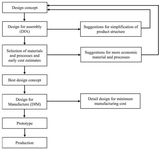
Boothroyd (1994) advocated that DfA should be the primary concern for product design, resulting in a simplified product structure. Next comes the economical selection of materials and procedures, and then preliminary cost estimation. To reach a trade-off choice, cost estimates for the original design and the new (or improved) design will be compared thereafter. Once the materials and methods have been finalized, a more complete DfM study will be conducted. DfM is provided with standards, component design, and component assembly for lowering the total cost of production. The general series of DfMA procedures are illustrated in Figure 13 (adapted from [1][33]).
Boothroyd et al. [25][57] enlisted the three major criteria for the application of DfMA to resultant products as shown below:
- (1)
-
The design team reduced the product’s structure to save manufacturing and assembly expenses and to enhance product quality.
- (2)
-
A tool for quantities issues in their manufacture and assembly was developed.
- (3)
-
A tool for reducing costs and negotiating contracts with suppliers was also created.
Bogue [26][58] stated that there were three means to implement a DfMA procedure. One step was to adhere to a general set of qualitative and non-specific principles or standards and need stakeholders (usually designers and engineers) to interpret and apply them in specific cases. The objective was to include a variety of goods, techniques, and materials. The second technique quantifies the design. Each part’s “assemblability” was scored. The last was a process automation technique where the design process might be quantified using computerization software. Similarly, Stoll [27][59] outlined ten DfMA principles and rules including (1) minimizing the total number of parts; (2) developing a modular design; (3) utilizing standard components; (4) designing parts to be multifunctional; (5) designing parts for multiple uses; (6) designing parts for ease of fabrication; (7) avoiding separate fasteners; (8) minimizing assembly directions; (9) maximizing compliance; and (10) minimizing handling. Kim et al. [28][60] also standardized 13 bridge constructions in the United Kingdom based on DfMA criteria. Jung and Yu [29][61] recently developed a DfMA checklist to evaluate the optima of design plans for offsite construction projects by outlining optimal design goals, the process, and DfMA principles. The documentation process of DfMA is still in the early stage.
Researchers and building owners are developing an interest in modular and prefabricated construction projects based on the DfMA. In these projects, building components are built in a factory and then sent to the construction sites, where they are assembled. Consequently, many research articles concentrating on the essential technologies for implementing DfMA in sustainable building, renovation, and interior projects were published [30][31][32][33][20,62,63,64]. For example, Serra [34][65] developed Australia’s high-rise construction bathrooms with DfMA-based flat-pack walls saving almost one-third of operating energy usage owing to its efficient design. Furthermore, Wasim et al. [35][66] utilized DfA to quantify the efficiency of prefabricated non-structural timber construction components for residentials. Their case study revealed that the DfA of the timber frame and drainage manufacturing system will be 9.8% and 10.244%, respectively. The DfMA can be performed for mechanical, electrical, and plumbing (MEP) systems for improving producibility and product quality throughout the product development process [5][37]. It is found that DfMA for modular and prefabrication techniques can be well applied to the Dfab and DFAM methods. The differences can be detailed such as differences in production and machine techniques, textures and patterns, structural performance, structural loading calculation, design softwares (i.e., G-code and slicing), and jointing techniques.
Exploration of industrial innovation, particularly offsite building, has presented DfMA with a distinct opportunity. DfMA is at the forefront of the industry’s cross-sectoral learning and innovation agenda due to the parallels between offsite construction/prefabrication and manufacturing. In addition, rising technical innovations such as building information modeling (BIM) [36][37][38][67,68,69], 3D printing [39][40][41][4,70,71], the Internet of Things (IoTs) [42][43][72,73], and DfMA in particular, new entry opportunities of design and construction aspects for manufacturing expertise and efficiency improvement.
3. DfMA for Digital Fabrication (Dfab) and AM (DfAM)
In this section, two DfMA processes related to Dfab and DfAM were discussed. The number of technical publications that represent DfMA for Dfab and DfAM in construction is quite minimal. The researcheuthors reviewed existing articles from Scopus and Google Scholar databases relating to DfMA for Dfab and DfAM. Table 23 summarizes the existing 35 publications regarding DfMA for Dfab and DfAM. Based on these 35 publications, it is revealed much is emphasized on DfMA for DfAM (74%) in construction as illustrated in Figure 24a). The research publication analysis also found that current publications are published after 2018–2023 as shown in Figure 24b). Meaningly, the studies on the DfMA for DfAM topic are fairly novel and have been tremendously growing within the five recent years (about 70%).
Table 23.
The summary of 35 existing publications on DfMA for Dfab and DfAM in construction.
| Year | Author | Process | Discussion | Reference |
|---|---|---|---|---|
| 2011 | Williams et al. | DfAM | Design system focuses on three aspects: identifying essential use cases, defining formwork systems, and defining software element communication to facilitate expert user cooperation. | [44][74] |
| 2014 | Wang et al. | DfAM | Integration of 3D printing, BIM, and augmented reality is needed to improve architectural visualization in building life cycle. | [45][75] |
| 2015 | Bock and Linner | Dfab | Product structures and information aspects required manufacturing technology for full capability | [4][36] |
| 2015 | Yang and Zhao | DfAM | General Design Theory and Methodology (DTM) cannot take use of the enhanced design freedom and process options. Modifying standard DTM and DfAM can help designers effectively use AM in designs. | [46][76] |
| 2016 | Wu et al. | DfAM | BIM and 3D printing synergize to provide new DfMA possibilities in the building business. BIM can create an accurate 3D integrated information model for building design and 3D printing. | [47][5] |
| 2016 | Tang and Zhao | DfAM | Few product-level design approaches exist for both functionality and assembly, and some current design methods are challenging to execute due to an unfit CAD software. | [48][77] |
| 2016 | Tang et al. | DfAM | Establishes the basis for sustainable AM design through functionality integration and component consolidation. DfMA offers designs with fewer parts and less material without sacrificing functionality. | [49][78] |
| 2016 | Kim et al. | Dfab | An interview determines the acceptability of precast bridge components based on DfMA requirements. A case study on a newly completed highway bridge identifies the possibility of precast components selected from suitability analysis. | [28][60] |
| 2017 | Krimi et al. | DfAM | 3D printing provides design flexibility and cost savings to build complicated forms, not the time-saving. | [50][79] |
| 2018 | Arashpour et al. | DfAM | In advanced façade manufacturing, a substantial portion of the expenditure is for equipment such as CNC machines and 3D printers which can be significantly reduced by DfMA. | [51][80] |
| 2018 | Durakovic | DfAM | Most 3D printing studies are still in early stages. This method lacks numerous technologies; therefore, maturity will take time. | [52][81] |
| 2019 | Ng and Hall | Dfab | LEAN, DfMA, and Dfab share design to target value and concurrent engineering. | [53][82] |
| 2019 | Dorfler et al. | Dfab | Mesh mould is a novel construction technology for non-standard reinforced concrete buildings employing a mobile robot on site. | [54][83] |
| 2019 | Hinchy | DfAM | 3D printing is ideal for low-volume, sophisticated components, hence it should be selected over traditional methods. Build orientation and support structures affect manufacturing cost, time, post-processing, and final component mechanical characteristics. | [55][84] |
| 2019 | Medelling-Castillo and Zaragoza-Siqueiros | DfAM | Build orientation affects component stability during construction by determining the part’s support surface on the building platform. | [56][85] |
| 2020 | Ng et al. | Dfab | Dfab manager and Dfab BIM coordinators are needed early in the design process. | [57][86] |
| 2020 | Alfaify et al. | DfAM | The suggested DfAM solutions include cellular structures, component consolidation and assembly, materials, support structures, build orientation, part complexity, and product sustainability. | [58][87] |
| 2022 | Nguyen et al. | DfAM | DfMA attempts to optimize product design to deal with complicated production processes while specifying 3D-printed product advantages throughout its consumption phases. | [59][88] |
| 2020 | Ghaffar et al. | DfAM | Collaboration across materials science, architecture/design, computer, and robotics is important to developing and implementing 3D printing. | [60][89] |
| 2021 | Gibson et al. | DfAM | Modern 3D printing has led to more emphasis on DfAM training. | [61][90] |
| 2020 | Frascio et al. | DfAM | This solution tackles the exponential link between construction volume and printer cost and improves efficiency by deploying many 3D printers simultaneously. | [62][91] |
| 2021 | Ng et al. | Dfab | Three design practices were identified: post-rationalization, mass customization, and modularization. | [63][92] |
| 2021 | Graser et al. | Dfab | Three theoretical factors for using Dfab house projects: full-scale projects are an effective Dfab strategy in AEC; large-scale implementation promotes Dfab’s acceptability in AEC; and projects help develop a new Dfab paradigm. | [64][93] |
| 2021 | Ghiasian | DfAM | Intelligent machine learning-based recommender system that identifies part candidates and addresses AM infeasibilities in existing component designs. | [65][94] |
| 2022 | Prasittisopin et al. | DfAM | Small modules for 3D-printed pavilions can be attached together using bolt–nut designs. | [66][18] |
| 2021 | Morin and Kim | DfAM | The optimization scheme’s effectiveness in breaking a cantilever beam structure into components that fulfill the AM build plate’s geometric restrictions while reducing the structural impact of joints. | [67][95] |
| 2021 | Vu et al. | DfAM | DfMA framework entails three main elements: structure, property, and process. | [68][96] |
| 2022 | Ng et al. | Dfab | Proposed seven strategy propositions to achieve the benefits of adopting Dfab system. | [69][97] |
| 2022 | Rankohi et al. | DfAM | Integration of 3D printing, DfMA, and BIM can boost automation and productivity even with present labor difficulties. | [70][98] |
| 2022 | Sadakorn et al. | DfAM | Similar to the precast method, the jointing can be executed in dry process. | [71][99] |
| 2022 | Nguyen et al. | DfAM | Parametric model for bridge pier improved industrial output. | [72][100] |
| 2022 | Spuller | DfAM | Unlike product design application, construction occasionally uses DfAM. | [73][101] |
| 2022 | Song et al. | DfAM | New DfAM knowledge must be organized into general frameworks to assist practitioners throughout the product design process and to properly leverage present AM capabilities and developing potentials. | [74][102] |
| 2022 | Qin et al. | DfAM | Machine learning has contributed significantly to DfAM and has the potential to revolutionize AM. | [75][103] |
| 2023 | Rehman et al. | Dfab | Two most important liability factors are management capability and BIM. | [43][73] |
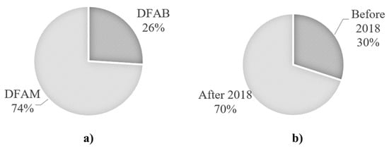
Figure 24. Relative research number of (a) DfMA for DfAM and Dfab in construction; and (b) published before 2018 and after 2018 (among a total of 35 existing papers).
3.1. DfMA for Dfab
Dfab is rising as a systematic breakthrough in the AEC sector to stimulate automation and enhance efficiency. It is necessary to incorporate manufacturing knowledge in the early design process. Bao et al. [32][63] addressed that a block-brick-based wall, hollow-brick-based wall, and shear wall system used skirting line connection, stitch connection, and tight connection, respectively. A paperless design and construction process can be supported by Dfab, which results in cost savings [76][104]. In addition, it offers a number of environmental, social, and economic advantages, including the reduction of waste, the removal of physical inventory, the reduction of labor, the implementation of digital quality control, and the establishment of an offline part setup [77][105]. The typical Dfab techniques consist of two methods computer numerical control (CNC) and laser cutting. Based on DfMA, Bridgewater [78][106] suggested DfA for factory-based production and onsite automation to reduce the number of components for Dfab such as robotics. He also mentioned rules for redesigning building systems for DfA, as well as a new construction contract and legal requirements for DfA. Bonwetsch [79][107] advocated that CNC let design information be sent directly and automatically to fabrication machines. Robotics focused on integrating design and construction, which helped to cut down on construction costs and time and improve the quality of design. Examples of how DfMA works for robotics and how codes and designs could be combined early in the design process were addressed.
The parameters found by Dfab could affect both design results and process. During the design process, all physical constraints of fabrication had to be taken into account. Martinez et al. [80][108] indicated how the robotized Field Factory System was designed using DfMA principles and how its production lines were set up. For instance, the factory layout took into account the size and range of motion of an ABB robot. The Service Core has been examined to improve the time and quality of assembly holistically. Montali et al. [81][109] determined the Knowledge-Based Engineering (KBE) approach using digital tools to support design through the automation of reusable knowledge on facade design with DfMA principles. They found that the 2D and 3D digital tools that were currently available could not close the design-manufacturability gap in the facade construction industry. The DfMA-based KBE for design automation was proposed to guide design from the beginning of the design process to improve quality, reduce delivery time and costs, cut down on rework, and support product development in construction. Furthermore, CNC milling was conducted to investigate the principles of DfMA [51][80]. Ng and Hall [63][92] conducted an online game with the Target Value Design (TVD) principle for modeling the Dfab construction. TVD principle implies a strategy that was built on lean principles and incorporates a design based on thorough cost estimates [82][83][110,111]. Concurrent engineering, design-to-target-values, and the maximization of values to project stakeholders were possibly conducted by TVD. They found that TVD was offered as a feasible design management strategy for managing Dfab during the design process and maximizing value for project stakeholders. However, the application of Dfab in TVD in the construction sector is still relatively new. The prerequisite for future assessment is required. Parametric modeling also supports collaborative work, which makes it easier to put DfMA into practice. Ng [69][97] reviewed 59 journal articles about Dfab and discussed how DfMA had several important enablers. These included Dfab engineers, parametric or computational resources, visual-programming conditions, bespoke/customized design and modular features, Dfab optimizing and prefabrication processes, an artifact of Dfab physical mockup, value of reducing human dependence, along with risks of increasing uncertainty in production and performance compromise/uncertainty. De Soto et al. [84][112] determined the productivity, cost, and time aspects of the onsite robotic fabrication technology. Results found that complex decoration structures could be made with Dfab at no extra cost. This is because Dfab can build a part in a more integrated way by obtaining feedback early in the design process, as also discussed in the full-scale Dfab house under the NEST project developed by EMPA, Switzerland [85][113]. Regardless of the fact that only a limited number of investigations have been presently performed on Dfab technology, these Dfab principles are apparently in accordance with the DfMA principles and may be adopted without issue.
3.2. DfMA for DfAM
DfMA tools facilitate communication between product designers, production engineers, and any other stakeholders in the finished product. Barbosa [86][114] asserted that DfMA was an essential method for boosting the productivity of any product development via design in several manufacturing sectors. However, the AEC sector did not give building designers similar techniques. In an increasingly dispersed work environment, the integration of construction expertise into the design phases continued to rely on the experience of individuals [87][115]. Furthermore, Spuller [73][101] mentioned that in contrast to the domain of product design, the building sector made relatively infrequent use of these DfAM methodologies.
Figure 35 shows the complexity levels of DfAM techniques. Both direct component replacement and DfAM can be viewed as processes of manufacturing-driven and function-driven design strategies, respectively. The adaption of AM represents the medium ground between the two sides. To take advantage of AM, the design of a component can be modified, but its connections to other components are maintained in their previous states [88][116].
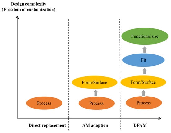
Figure 35.
Complexity levels of DfAM.
First, the direct replacement (leftward) is the basic design process for the manufacturing process. From a traditional manufacturing standpoint, the Handbook for Product Design for Manufacture by Bralia [89][117] and Product Design for Manufacture and Assembly by Boothroyd et al. [25][57] addressed suitable instances of design for manufacturing standards and practices. The substantial work on design for manufacturing over many years indicated the complexity and pervasiveness of the design for manufacturing concerns [90][118]. It is necessary for designers to have a solid grasp of the limits imposed by accessible fabrication technologies. Some of these restrictions are alleviated by AM, while others are not. The applicability challenges for design for manufacturing in AM are shown in the following areas where traditional design for manufacturing falls short of the benefits offered by AM. The applicability challenges include:
-
Layerwise operational characteristics and direct CAD model production extend part design creativity.
-
Parts could be created as modular 3D puzzles incorporating small modules.
-
As AM materials may be treated point-by-point or layer-by-layer, complicated material compositions and property gradients are possibly adopted.
-
AM allows for the fabrication of hierarchically complicated, long-scale building designs.
AM’s distinctive technique allows for low-cost, fast remanufacturing and repair. AM capabilities represent the complexity of shapes and surfaces in designs. It is feasible to create almost any form, allowing for various lot sizes starting from one, rapid customization of geometries, and shape optimization. Some studies determined using the inner truss as a surface of the architectural wall structure of the building [71][91][99,119]. Results indicated that several patterned AM wall structures could be created based on a geometric ratio. This led to a reduction in material consumption and printing time. Nguyen et al. [72][100] developed bridge constructions that were prefabricated using AM adoption. Throughout this work, a unique digital engineering model approach was developed by combining current knowledge of DfMA with structure-oriented parametric modeling technology. The geometrically complex elements of bridge piers that were aligned with the aesthetic surfaces were built using DfMA approaches and parametric modeling.
Lastly, the DfAM as shown in the rightward of Figure 35 entails two additional steps (fit and functional use). The “fit” term means the assembly process. To reduce assembly time, cost, and challenges in conventional assembly, two primary ideas are frequently offered: reducing the number of pieces and eliminating fasteners. Both factors immediately result in fewer assembly procedures, which was the main cost driver [25][57]. Mavroidis [92][120] stated that, conventionally, the primary role of the assembly was to link together components, freeform material, and small elements to create a complex product. In contrast to typical assembly processes, AM permitted the consolidation of elements in locations where they were previously manufactured independently owing to manufacturing restrictions, material differences, and cost. AM reduces manufacturing limits and gives a fundamentally different viewpoint on jointing than conventional assembly. The issues associated with design considerations for AM assembly are covered as follows:
-
The layer-by-layer or point-by-point nature of AM makes it easier to combine and embed parts. Most applications can be put into two groups: those that use operational mechanisms and those that use embedded components. In the case of operational mechanisms, if two or more parts need to be able to move in relation to each other, AM can build these parts already put together. For this type of non-assembly mechanism, one of the most crucial factors was joint clearance [93][121]. The joint clearance could reform the way the mechanism works. In addition, in the case of embedded components, it is often essential in building a functional prototype by putting components into a part. This can improve the performance of the holistic system.
-
AM is a good way to fabricate a structure with more than one material. The use of more than one material in AM can be applied to improve the functionality of the printed element. The multiple nozzle heads of extrusion AM have been examined [94][95][96][19,122,123]. Classen et al. [97][124] made fork-shaped, multi-nozzle extrusion heads for layer thicknesses of 50–100 mm and filament widths of 180–240 mm. The goal was to set up a fully automated, high-speed process for making continuously steel-reinforced concrete walls. Khoshnevis et al. [98][125] introduced supporting material, such as wax and sand, along with the concrete nozzle. This can be adopted for better buildability and can be built as a roof structure. Aside from these, multi-nozzle AM can produce complicated structures such as concrete extruded nozzles and spraying nozzles for either smoothing the surface or creating a range of surface textures.
Another step, shown in Figure 35, is the “functional use” which can be mainly structural performance as a structural building component. Historically, products with basic geometries have been favored despite losing functionality or performance. This leads to material cost savings. To increase structural performance, AM structures are designed to be multifunctional and adaptable. The capability of DfAM to generate extremely flexible and functionally integrated components encourages the development of intelligent components that rapidly adapt to and respond to the operating environment [99][100][126,127]. Another virtue of AM is freeform printing, allowing for the creation of cellular structures. Based on topology optimization, it is possible to design a hollow structure that results in less weight and decreased material consumption. Nauyen and Vignat [101][128] asserted that the topology optimization approach permitted the identification of optimal material distribution and the reduction of material consumption while maintaining the mechanical qualities of the product. Additionally, in the case study of AM bridge piers, by relating the DfAM parameters to the estimated moment–curvature curves, the seismic performance of a bridge pier analyzed by the finite element method was achievable [91][119]. Vu et al. [68][96] advocated that optimized micro-structures could be self-supporting only in particular instances, such as when the load was equally distributed, and the micro-structures were anisotropic. Moreover, Morin and Kim [67][95] assessed the topology optimization for DfAM when the build area was limited. From their work, a structural cantilever beam case study was employed. Preliminary findings showed the optimization scheme’s usefulness in decomposing the cantilever beam structure into components that could fulfill the AM build plate’s geometric restrictions.
In addition to the structural performance aspect, other functional purposes such as thermal and acoustic insulation performance, MEP, and Heating Ventilation and Air Conditioning (HVAC) systems can be designed into the AM structure. Prasittisopin et al. [102][22] developed a textured AM wall with a hollow structure that allowed the structure to perform thermal resistance to sunlight in a tropical climate. The AM wall could end up in electricity expenditure by almost 50%. Karadeniz and Toksoy [103][129] also mentioned that the HVAC system could be successfully implemented in AM through DfAM, followed by Heat Recovery Ventilation (HRVU) and Air Handling Unit (AHU) systems. DfAM methods were designed to aid designers in making decisions at the design stage to fulfill functional requirements while maintaining manufacturability in AM systems and to aid manufacturers in their fabrication process [56][85]. DfAM includes four steps for process, form/surface, assembly, and functional use, allowing for greater levels of design complexity or customization freedom.