Your browser does not fully support modern features. Please upgrade for a smoother experience.
Please note this is a comparison between Version 2 by Rita Xu and Version 1 by Jianxin Zou.
Large-scale energy storage with high performance and at a reasonable cost are prerequisites for promoting clean energy utilization. With a high theoretical energy density of 1722 Wh·kg−2, high element abundance (e.g., Mg of 23,000 ppm, S of 950 ppm on earth), and low theoretical cost, Mg-S batteries offer considerable potential as candidates for electrical energy storage. This review summarizes recent research progress in sulfur cathodes, interlayers, and non-nucleophilic electrolytes, highlighting the main challenges and corresponding strategies for electrode material design.
- magnesium sulfur batteries
- sulfur-based cathodes
- Mg polysulfides
- interlayer modification
- functional separator
- electrolyte
1. Introduction
To achieve word-wide carbon-neutrality, tremendous attempts have been made to reduce carbon emissions, putting great pressure on developing green energy technology [1]. However, green energy technologies, such as solar, wind, and tidal, are limited by geography or time uncertainty. Because of this, developing large-scale energy storage conversion systems are urgently required. Although lithium-ion batteries (LIBs) are widely used, they still suffer from critical defects, including limited reserves, high cost, and potential security liability [2,3][2][3]. Consequently, beyond Li+, e.g., Na+, K+, Mg2+, Zn2+, and Al3+ batteries remain appealing [4,5][4][5]. Among them, rechargeable magnesium-ion batteries (RMBs) have aroused wide interest, ascribed to Mg metal’s high theoretical volume specific capacity of 3833 mAh·cm−3, which is close to twice that of lithium (2046 mAh·cm−3) and nearly five times that of graphite (800 mAh·cm−3). Although magnesium’s standard electrode potential (Mg2+/Mg, −2.36 V vs. SHE) is lower than lithium (Li+/Li, −3.05 V vs. SHE), it is significantly higher than aluminum and zinc (Al3+/Al, −1.66 V vs. SHE; Zn2+/Zn, −0.76 V vs. SHE) [5,6][5][6].
Magnesium primary batteries were first commercialized in 1943 (Figure 1), offering a voltage plateau of 1.6 V, and are widely used in military and aerospace backup power supplies [7]. Gregory and co-workers at Dow Inc. initiated research on RMB electrolytes with high Coulombic efficiencies beginning in 1990 [8]. In early 2000, Aurbach and colleagues [9] made use of Chevrel phase Mo6S8 in RMBs, achieving more than 2000 cycles, signifying a breakthrough for RMB technology. A second breakthrough came with the discovery of all-phenyl-complex (APC) electrolyte by Aurbach and co-workers [10]. In 2011, Kim and Muldoon et al. first proposed a proof-of-concept Mg-S battery with a non-nucleophilic electrolyte of MgCl2(HMDS)-AlCl3, with a high discharge capacity of 1200 mAh·g−1 and 2484 mAh·cm−3 [11]. Since then, Mg-S battery research has drawn increasing interest because of the natural earth abundance of the raw materials (e.g., Mg of 23,000 ppm, S of 953 ppm), 1680 Wh·kg−1 and 3220 Wh·L−1 theoretical energy density, a suitable potential window in ether-based electrolytes, and improved safety from dendrite-free deposition behavior [12,13,14,15][12][13][14][15].
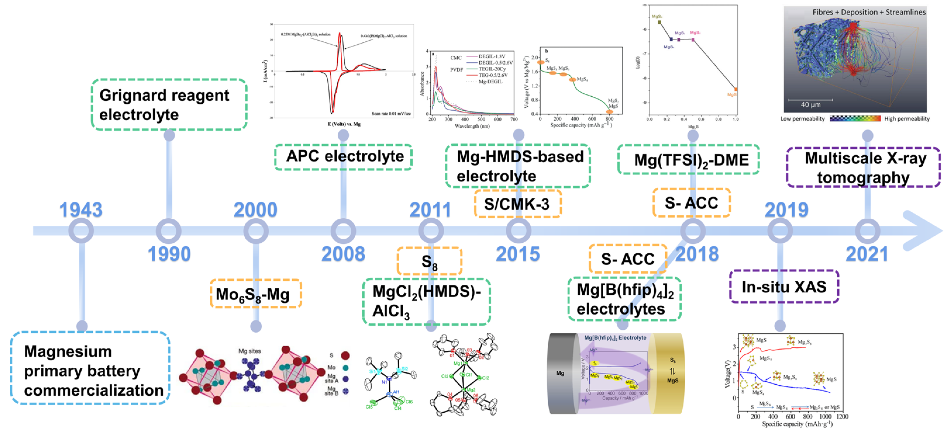
Figure 1. The history of RMB development beginning in 1943 in terms of electrolyte (green), cathode (orange), and characterization techniques (purple). Grignard reagent electrolytes. Mo6S8 as RMB cathode materials. The invention of APC electrolyte. The first proof-of-concept Mg-S battery using MgCl2(HMDS)−AlCl3 electrolyte. The first application of ionic liquids as the electrolyte solvents and S/CMK−3 as the cathode. Investigation of Mg[B(hfip)4]2 electrolyte. The first use of S/ACC active material. In situ XAS and multiscale X−ray tomography applied to investigate the electrochemical conversion in Mg−S batteries.
Despite its promise, multiple scientific problems need resolution. For example, the rapid and facile formation of MgO severely passivates Mg metal anode surfaces, and Mg2+ exhibits high polarization greatly impeding diffusion in cathode lattices. Gao et al. [18][16] used X-ray photoelectron spectroscopy (XPS) analysis and found that the discharge path in Mg-S batteries is akin to Li-S batteries, for which multiple processes S8 → MgS8 → MgS4 →MgS2 → MgS occur, indicating that Mg-S batteries must be designed to overcome polysulfide shuttling. In addition, as an electrophilic cathode, sulfur must be matched with a non-nucleophilic electrolyte to avoid side reactions. However, regarding Mg-S battery technology itself, cathode materials’ development is still in its infancy. There is a critical need to understand and improve the structure and compositions of cathode materials to enhance storage capacity, rate capability, and cycling performance.
2. Reaction Mechanisms and Challenges in Mg-S Batteries
2.1. Reaction Mechanisms in Mg-S Batteries
Although Mg-S batteries were first proposed in 2011, there remain multiple electrochemical reactions and failure mechanisms to be clarified [21,22][17][18]. Schemes I-III present sulfur reduction mechanisms extant during the discharge process. Figure 2 illustrates the process whereby elemental sulfur gradually generates long-chain polysulfides (LCSs) that are then reduced to short-chain sulfides (SCSs) or MgS.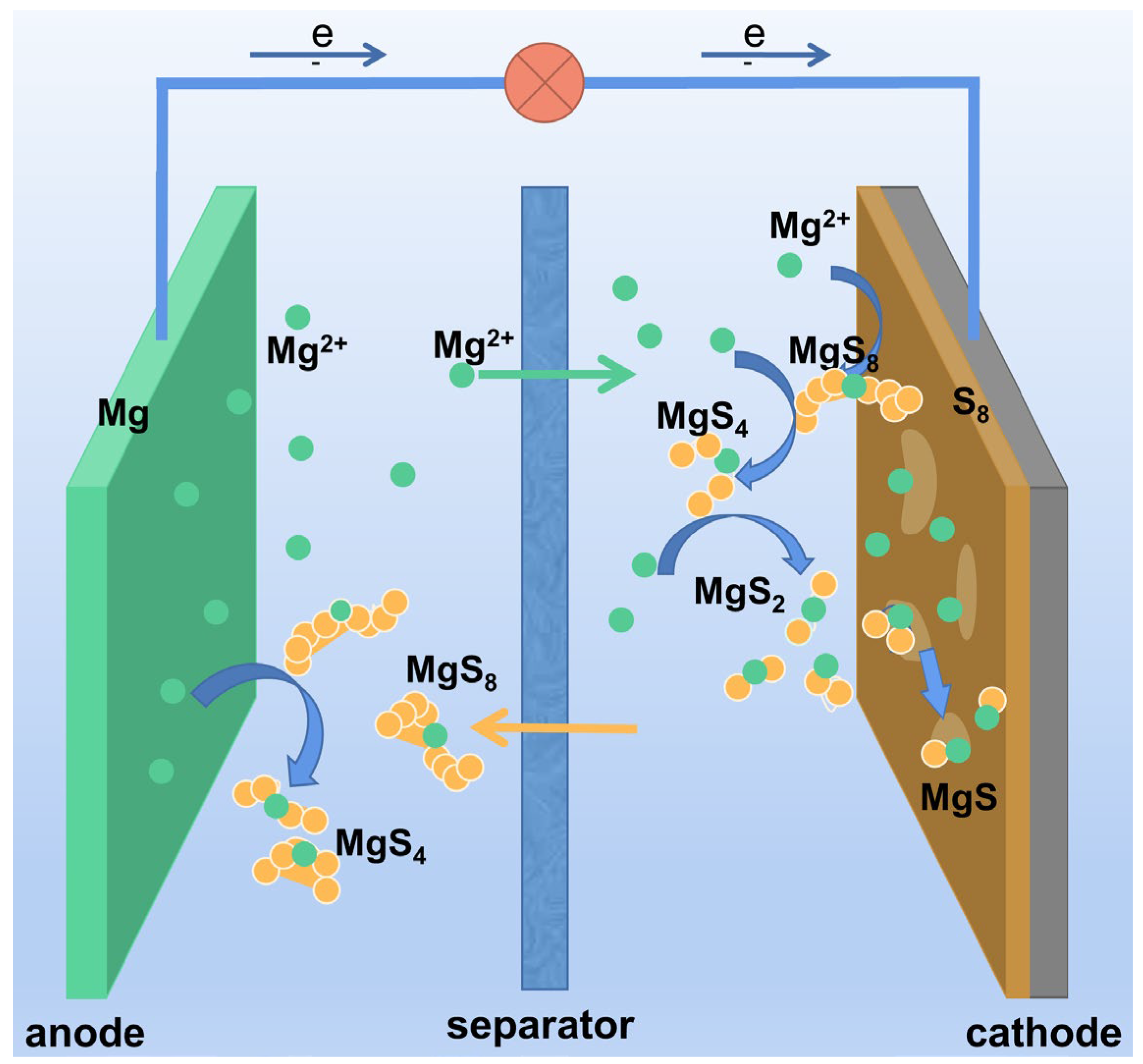
Figure 2. Illustration discharge reaction mechanism for Mg−S batteries.
Scheme I:
Scheme II:
Scheme II:
As mentioned above, Gao et al. [18][16] found by XPS that sulfur first forms LCSs at 2.4–1.5 V, and then SCSs at 1.5 V, and finally MgS at 1.5–0.5 V in Mg(TFSI)2-DME electrolyte (Figure 3a). According to the kinetic factor obtained from CV curve fitting and ab initio molecular dynamics (AIMD) simulation, Schemes I and II are mixing-controlled reactions, while Scheme III is a diffusion-controlled reaction. As MgS exhibits a strong tendency to crystallize and MgSx (x = 2–8) tends to remain amorphous, Mg2+ diffusion becomes difficult when MgS is generated at the interface and the final product has a Mg concentration gradient from interface to depth. The reaction mechanisms for Mg-S batteries with S/CMK-3 cathodes and Mg-HMDS-based (glymes and additional ionic liquid as solvents) electrolyte were also investigated by Zhao-Karger and co-workers (Figure 3b,c) [16][19]. During discharge, S8 first forms MgS4 at 1.6 V offering a capacity of ~400 mAh·g−1. Thereafter, liquid-solid interfacial reduction occurs generating MgS2 with a theoretical capacity of 840 mAh·g−1, followed by reduction to MgS. This last process suffers from high dynamic barriers and polarization. Roughly the same conclusions can be reached for different electrolytes.
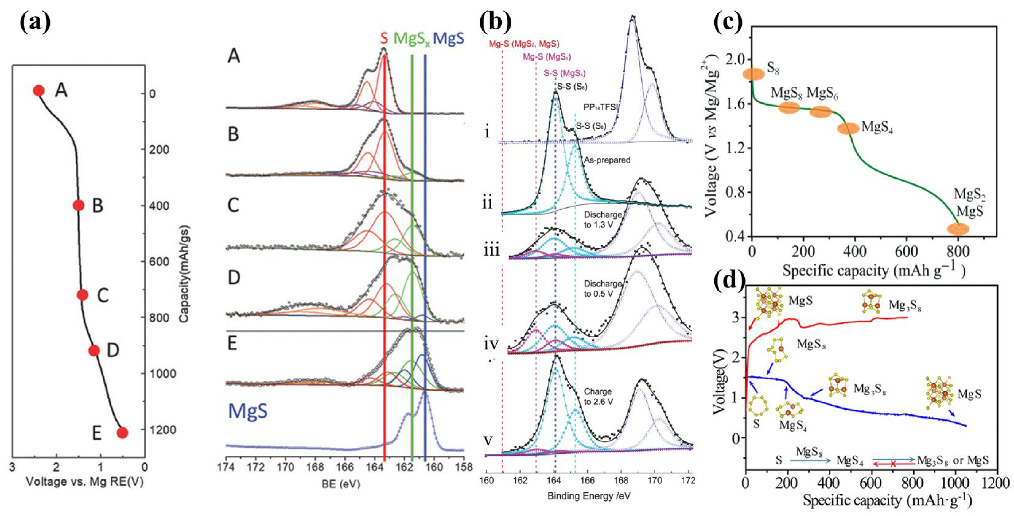

Figure 3. (a) XPS S 2p spectra of S/ACC cathode (S/C ratio = 0.11) at different states. (b) XPS of S/CMK400PEG cathode and Mg(HMDS)2 base electrolyte with ionic liquid PP14TFSI additives: (i) PP14TFSI, (ii) S/CMK400PEG, (iii) discharged to 1.3 V, (iv) discharged to 0.5 V, and (v) charged to 2.6 V, and (c) corresponding proposed mechanisms of discharge process. (d) Charge−discharge curves and proposed mechanisms in Mg(HMDS)2−based electrolyte.
Furthermore, researchers have used various in situ techniques to clarify Mg-S cell reaction mechanisms [19,23][20][21]. Dominko et al. used in situ XANES and RIXS to study Mg-S battery mechanisms, finding that S8 converts to polysulfides at a high voltage plateau and is then reduced to solid MgS. They also used NMR to characterize the discharge products. Mg is tetrahedrally coordinated in electrodeposited MgS, similar to wurtzite, while Mg in chemically synthesized MgS is octahedrally coordinated. Xu and co-workers [19][20] used density functional theory (DFT) calculations and in situ synchrotron X-ray absorption spectroscopy (XAS) to confirm that Mg3S8 produced in stage II is insoluble in the electrolyte; a consequence of an overpotential during cycling (Figure 3d). Moreover, the discharge products Mg3S8 and MgS have poor electrochemical activity and are difficult to oxidize to high-order polysulfides or sulfur, which leads to rapid capacity decay after the first discharge, reducing the cycle life. Coincidentally, Bhardwaj et al. [24][22] applied operando Raman spectroscopy to confirm the existence of higher-order Mg-polysulfides at high-voltage plateaus.
In addition, the dissolution and shuttling of S8 and polysulfides in electrolytes is also a critical problem [16,25,26][19][23][24]. Yellow discoloration of separators is often found in Mg-S batteries after a few cycles, indicating dissolved polysulfides [11]. Haecker and co-workers [23][21] used operando UV-Vis spectroscopy to determine the self-discharge behaviors under state of charge. After an OCV rest, severe self-discharge occurs, which can be divided into three stages: First, sulfur dissolves and is reduced to S6−2 and S4−2 on the Mg anode. Then, the S8 concentration in the electrolyte reaches equilibrium and the concentration of S6−2 and S4−2 increase steadily. Finally, the concentrations of S8, S6−2, and S4−2 reach equilibrium. About 0.6% sulfur in the form of MgSx was found on Mg foils after 50 cycles by ex situ XPS [27][25]. Coincidentally, Kimberly A et al. [25][23] employed a quasi-reference electrode of Ag2S to investigate the reaction between Mg metal and polysulfides, discovering severe reduction overpotential on the Mg anode surface (Figure 4a,b). Based on the shuttling of polysulfides, Mg is passivated in early cycles (Figure 4c). In another report, Zhao-Karger et al. [17][26] used X-ray energy dispersion spectroscopy (EDS) to analyze the elemental composition of the Mg anode after the 2nd and 18th cycles in sulfur-impregnated activated-carbon cloth (ACCS)-Mg cells, Figure 4d. Elemental sulfur was not detected on the Mg surface after the 2nd cycle, but was evident on the 18th cycle, indicating formation of MgSx or S films. However, there are no unifying conclusions on the failure mechanisms of Mg-S batteries. Hence, systematic research on the reaction mechanisms is still important as a prerequisite to identifying strategies for ameliorating known problems.
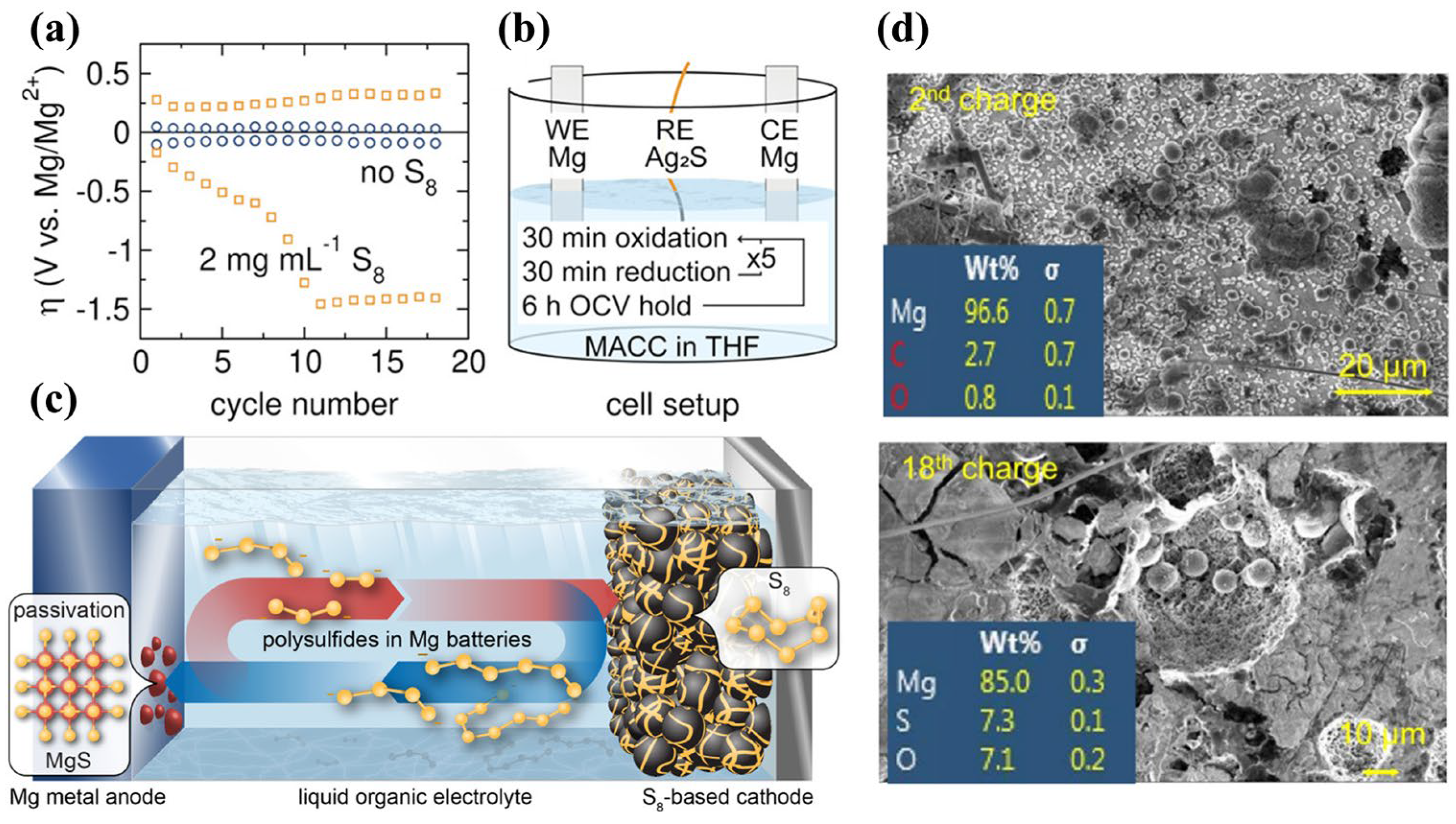

Figure 4. (a) Overpotential tests in Mg Symmetrical cells with and without 2 mg·mL−1 S8; (b) Schematic diagram of the three−electrode test; (c) Self−discharge and anode passivation mechanisms for Mg−S batteries. (d) Mg foil EDS in Mg[B(hfip)4]2 electrolyte after different cycle numbers.
2.2. Challenges in Cathode Materials
Dan-Thien and co-workers summarized failure mechanisms for Mg-S batteries, as shown in Figure 5 [28][27]. To address these weaknesses, researchers have proposed various solutions, such as the improved design of electrolytes [29[28][29],30], exploration of solid-state cells [31][30], synthesis of artificial anode SEIs [32][31], and the introduction of improved designs for cathode compositions and structures. Here, we present a review of the main challenges and strategies for the cathode side.
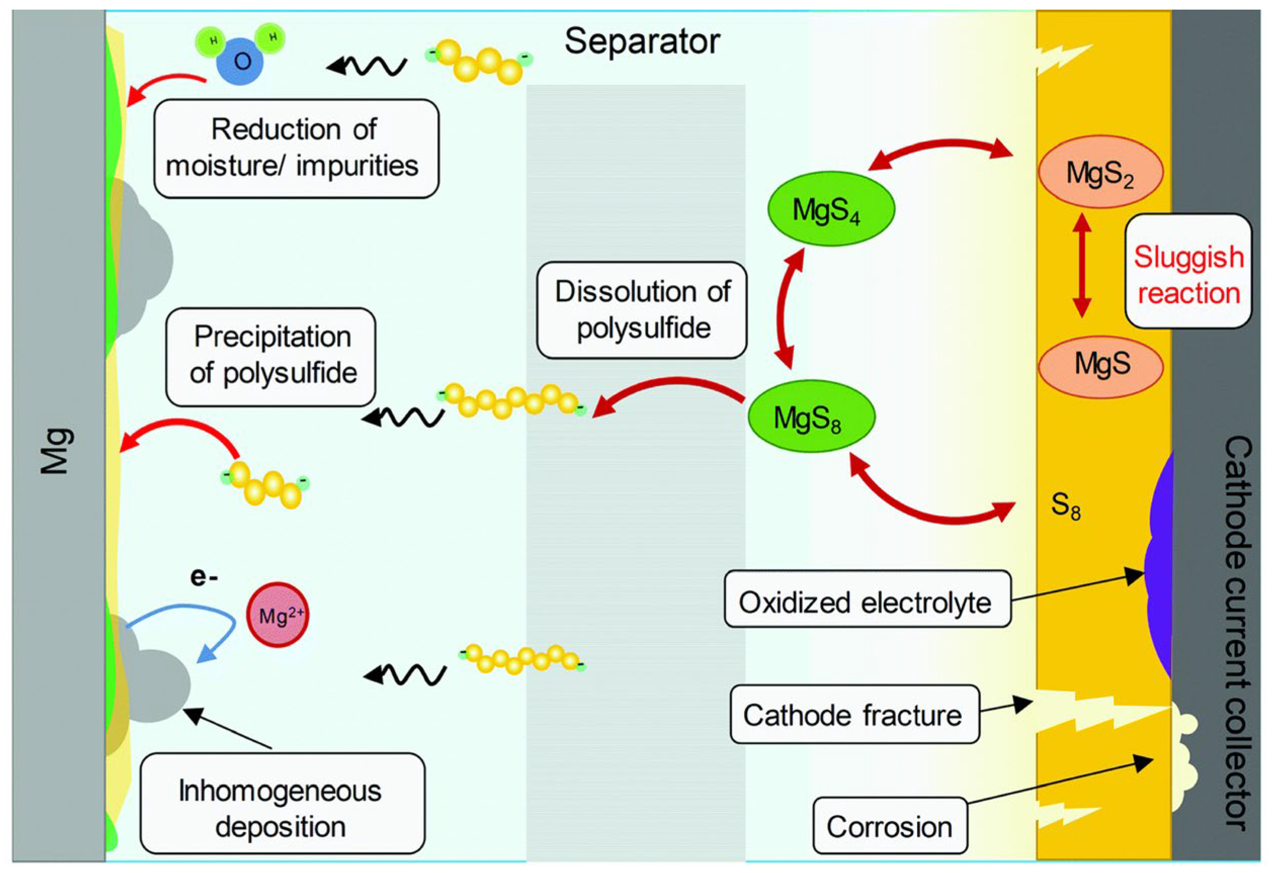

Figure 5. The general failure mechanism for Mg−S batteries.
(1) Improving the conductivity of electrode materials. Sulfur with an electric conductivity of 5 × 10⁻³⁰ S·cm−1 at room temperature functions as an electrical insulator, leading to severe ohmic polarization in Mg-S batteries. Therefore, compounding with highly conductive materials is a widely used strategy. For instance, graphene, carbon nanotubes (CNTs), MXenes, active carbon cloth (ACC) [18[16][32][33][34][35],33,34,35,36], and other materials [24,37,38][22][36][37] have been explored extensively.
(2) Prohibiting the effects of sulfur and polysulfide shuttling. As previously mentioned, the shuttling of sulfur and polysulfides in electrolytes often causes self-discharge, low Coulombic efficiency, and anode passivation, leading eventually to battery failures. Self-discharge has been verified systematically in different electrolytes, such as Mg[B(hfib)4]2/DME, MgFPB/DEG, and Mg(HMDS)2-AlCl3/THF [26,39,40,41][24][38][39][40]. SCSs are more likely to generate MgS on the Mg anode compared to LCSs, while MgS is an electrochemically inert material with a low Mg2+ diffusion rate, which partially passivates Mg surfaces [25][23].
Various types of sulfur hosts have been used to mitigate shuttling effects, of which physical confinement and chemisorption are well-known methods. Meanwhile, organic sulfur copolymers have been introduced to anchor sulfur by covalent bonding [42,43][41][42]. Recently, coatings or interlayers have been used between cathode/electrolyte to prohibit S8 and magnesium polysulfide transport, thereby eliminating any reaction of the anode with sulfur species [44,45,46][43][44][45].
(3) Mitigating the formation of stable compounds with low-formation energy. Mg-S batteries typically show severe capacity degradation from the second cycle, accompanied by high charge/discharge polarization. The discharge products in Mg(HMDS)2-based electrolytes were thoroughly investigated by Xu et al. [19][20] using in situ XAS measurement (Figure 3d). The discharge products Mg3S8 and MgS are nearly inert and do not reverse to higher-order magnesium polysulfides and S8, leading to rapid capacity degradation in subsequent cycles. Nakayama and co-workers [47][46] found that metastable zinc blende MgS is electrochemically active, while rock salt MgS is electrochemically inert.
(4) Enhancing cathodic mass transfer and reaction kinetics. High charge density is the source of slow Mg2+ diffusion in solids, more than twice that of Li+, leading to poor kinetics for Mg-S batteries. Lu and co-workers [48][47] reported that Mg-S batteries have lower concentrations of polysulfides during charge and discharge compared to Li-S batteries as determined by operando UV-Vis spectroscopy. Through three-electrode electrochemical characterizations, a stable low solubility S22− forms at the very beginning of discharge, which leads to the high overpotential at the cathode, and accounts for more than 50% of the cell overpotential. Thus, the first discharge capacity was successfully increased from 650 mAh·g−1 to 1500 mAh·g−1 by using dimethyl sulfoxide (DMSO) as a solvent. According to the above, increasing the solubility of MgSx could improve polysulfide dynamic performances and active material utilization rate. Furthermore, the application of lithium salt additives is also widely used to lower the kinetic barriers of Mg-S cells [49][48].
3. Research Progresses on Sulfur Cathodes
Physical Adsorption Cathode
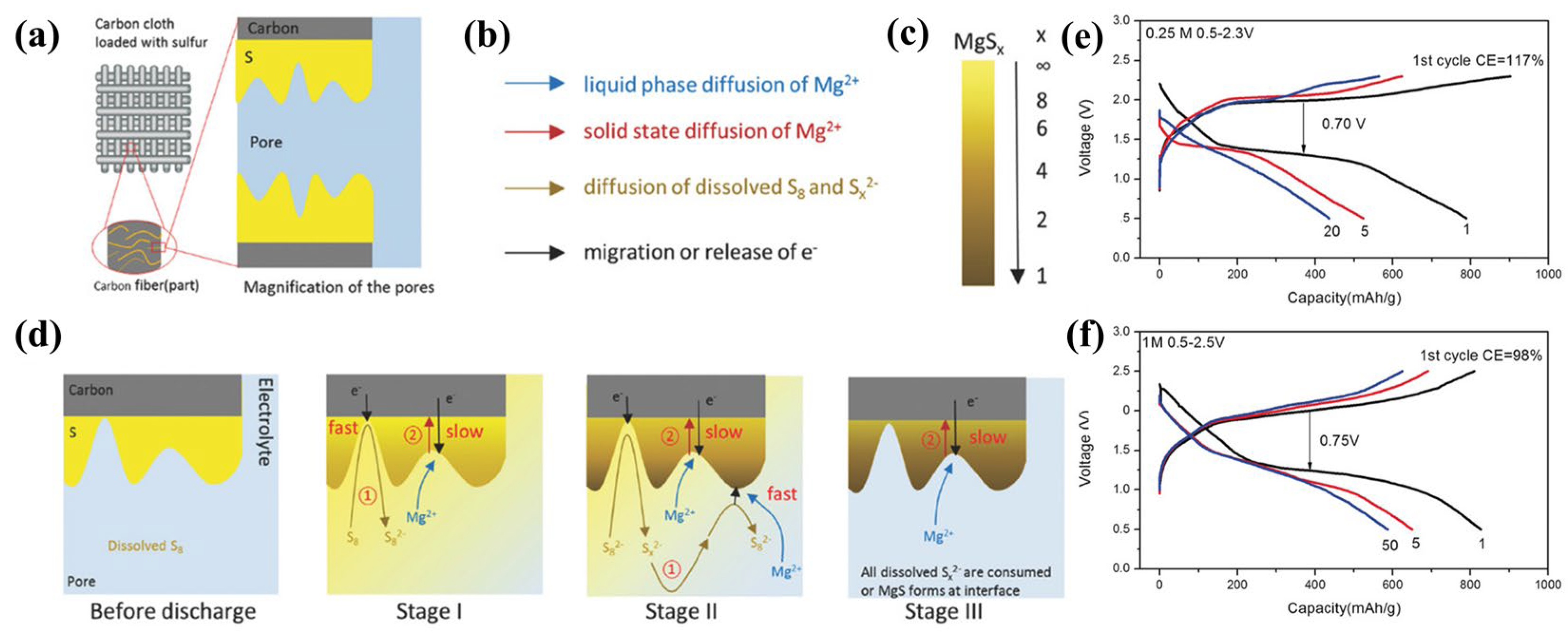
Mg-S cells suffer from issues, especially polysulfide dissolution and shuttling, the insulating behavior of S8, and critical electrode volume changes. In principle, physically trapped sulfur compounds with high electronic conductivity and chemical durability can improve sulfur utilization, mitigate polysulfide migration and retard the volume expansion of cathode active materials. Widely explored physically adsorbed sulfur hosts including activated-carbon cloth (ACC) [18,33,34,35,36][16][32][33][34][35] and porous carbon materials [24,37,38][22][36][37]. Sulfur-impregnated ACC (S/ACC) as a promising method for creating physically trapped “sulfur” for Li-S cells was first explored by Aurbach et al. [51][49]. It permits binder-free, exceptionally conductive three-dimensional structures, and superior specific surface areas (SSAs), which can decrease the escape of polysulfides allowing high sulfur utilization. Sulfur access to carbon fiber pores in ACC is achieved by melt-diffusion at 155 °C. The structure of a S/ACC composite cathode is shown in Figure 6a. Gao and co-workers [18][16] applied sulfur-impregnated ACC to investigate sulfur chemistry in Mg-S batteries with Mg(TFSI)2-DME electrolyte, which shows that S8 reacts stepwise, as illustrated in Figure 6b–d. Figure 6b,c further illustrate Figure 6b. The different colored arrows in Figure 6b correspond to different ion and electron transport pathways, and Figure 6c shows a gradual decrease in x in MgSx (1 ≤ x ≤ 8) as yellow shifts to brown, where brown indicates the formation of MgS. This also indicates the presence of a Mg concentration gradient in the final product from the electrode surface to depth. Moreover, a ~70% capacity retention cycling stability was found after 110 cycles through a combination of highly concentrated 1 M MgTFSI2/MgCl2/DME electrolyte and sulfur-impregnated ACC (Figure 6e) [35][34]. However, this improved electrochemical performance was achieved on the basis of ultra-low S:C ratios of 0.11, unfortunately not yet useful for practical applications. Muthuraj [36][35] used magnesium-polysulfide (MgSx) and polyaniline-coated carbon cloth (CC@PANI) to form self-supporting cathodes. First, a PANI layer was deposited on the ACC by in situ polymerization, and then the CC@PANI@MgSx cathode was synthesized by dropwise addition of MgSx solution (Figure 7a). CC@PANI serves as both a chemisorption and physical adsorption material. CC@PANI@MgSx cathodes show a discharge capacity of 514 mAh·g−1 and are stable for more than 20 cycles. Currently, the S/ACC sulfur loading is usually below 2 mg·cm−2, resulting in ultra-low S:C ratios.
Figure 6. (a) Structure of the S/ACC composite cathode. (b–d) The proposed sulfur reduction mechanism. ① Surface magnesiation. ② Bulk magnesition. (e) The S/ACC electrochemical performance in various concentrations of MgTFSI2−MgCl2/DME electrolytes.
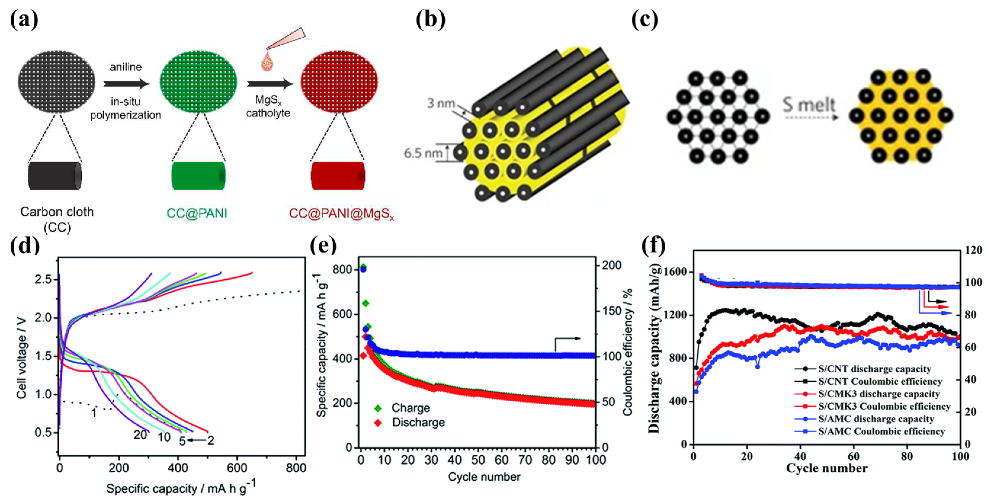

Figure 7. (a) Diagram of synthesis of CC@PANI@MgSx. (b) CMK−3 structure schematic. (c) Preparation schematic diagram of S/CMK−3. (d,e) The S/CMK−3 electrochemical performance in Mg [B(hfip)4]2 electrolyte. (f) S/AMC, S/CNT, and S/CMK−3 cycling performance in 0.5 M OMBB electrolyte with Cu current collector at 160 mA·g−1.
CMK-3, a highly ordered mesoporous carbon, with SSAs up to 2500 m2·g−1 and pore volumes up to 2.25 cm3·g−1, can be considered to offer significant potential as a physical absorption S host (Figure 7b) [16,52,54,55][19][50][51][52]. CMK-3 is first oxidatively carboxylated in HNO3 solution at 80 °C, then melt-diffused with S8 at 160 °C for 12 h (Figure 7c). S8 fills the 3 nm pores of CMK-3 [52][50]. Zhao-Karger and coworkers used S/CMK-3 cathodes and the non-nucleophilic electrolyte of Mg[B(hfip)4]2/DEG-TEG in Mg-S cells, successfully demonstrating an initial discharge capacity of almost 400 mAh·g−1 and cycling performance of 200 mAh·g−1 after 100 cycles at 167 mA·cm−2 (Figure 7d,e) [55][52].
Carbon S/nanofiber [56][53] and S/ketjen black [41][40] physisorbed hosts have also been prepared by melt-diffusion, showing specific capacities of 920 mAh·g−1 and 770 mAh·g−1 respectively. Du and colleagues [53][54] compared the performances of S/amorphous mesoporous carbon (S/AMC), S/CMK-3, and S/CNTs in Mg-S batteries, all of which showed excellent cycling performance with copper collectors, with discharge-specific capacities higher than 800 mAh·g−1 after 100 cycles (Figure 7f). However, capacity decay was detected for most carbon hosts after 20 cycles without Cu current collectors or lithium-salt additives.
Two-dimensional transition metal compounds (MXenes) are attracting increasing attention for their high electrical conductivity, rich surface functionality, and unique two-dimensional morphology, especially in energy storage devices [57][55]. Kaland and co-workers [38][37] first proposed Ti3C2Tx MXene as a free-standing material for Mg-S batteries. The cells achieved a specific capacity of 530 mAh·g−1 using an MXene interlayer (Figure 8a), and exhibited stable cycling with retention of >400 mAh·g−1 after 10 cycles, while the cells with no interlayer attained only 200 mAh·g−1 (Figure 8b). Xu [58][56] and Zhao [59][57] also prepared MXene with metal oxides/sulfide as a S host, which permits Mg2+ diffusion and transfer. S/Co3S4@MXene [59][57] with 75 wt.% sulfur loading and S/CoO@MXene [58][56] with 60 wt.% S loading exhibits high specific capacities of 1220 mAh·g−1 and 1500 mAh·g−1, respectively.
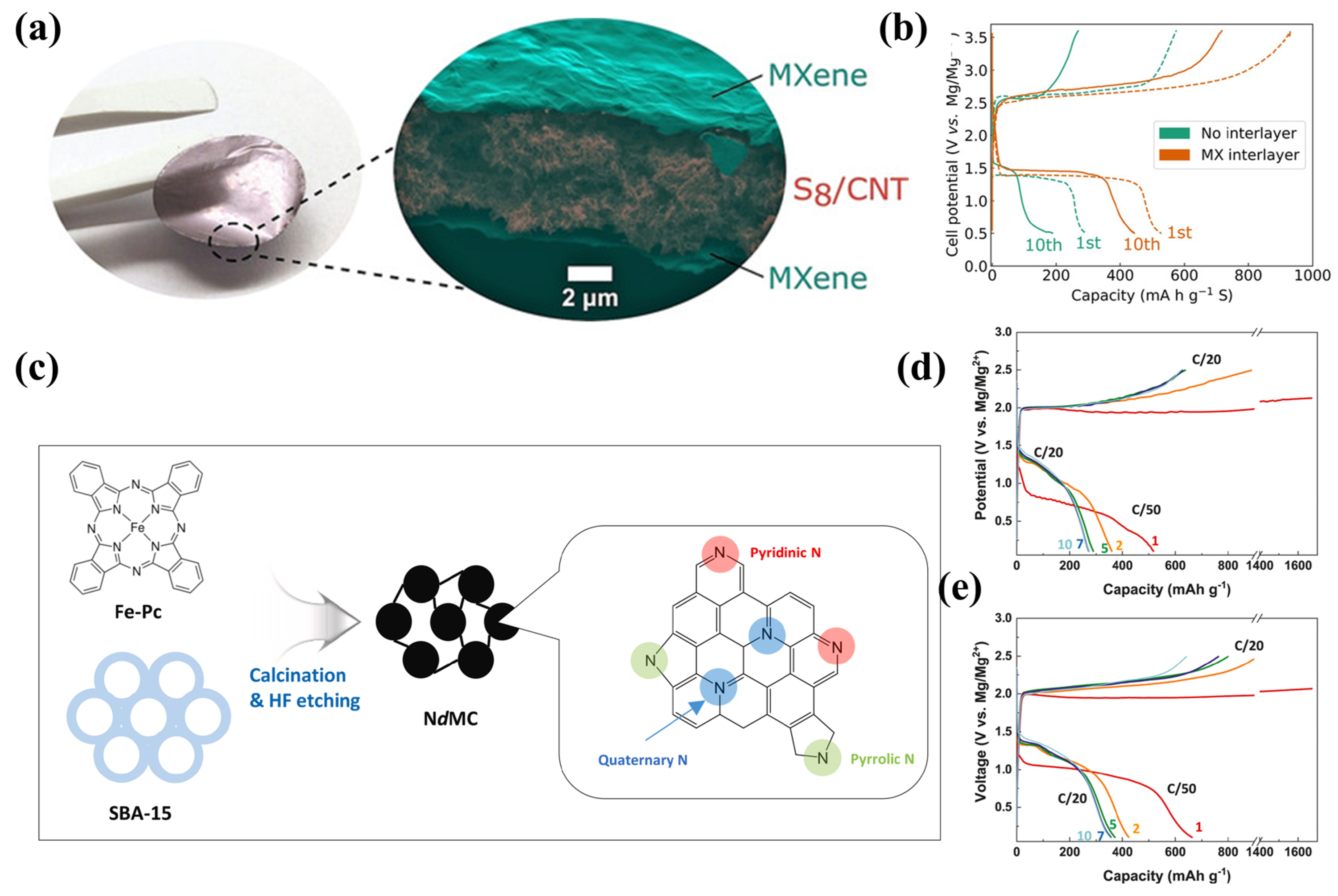

Figure 8. (a) Structural diagram of Ti3C2Tx MXene as free−standing cathode, and the corresponding (b) charge−discharge curves in Mg[B(hfip)4]2 electrolyte. (c) NdMC synthesis schematic. Charge−discharge curves of (d) S/CMK−3 cathode and (e) S/NdMC cathode.
References
- Franke, K.; Sensfuß, F.; Bernath, C.; Lux, B. Carbon-neutral energy systems and the importance of flexibility options: A case study in China. Comput. Ind. Eng. 2021, 162, 107712.
- Liu, J.; Bao, Z.; Cui, Y.; Dufek, E.J.; Goodenough, J.B.; Khalifah, P.; Li, Q.; Liaw, B.Y.; Liu, P.; Manthiram, A.; et al. Pathways for practical high-energy long-cycling lithium metal batteries. Nat. Energy 2019, 4, 180–186.
- Guo, Y.; Wu, S.; He, Y.-B.; Kang, F.; Chen, L.; Li, H.; Yang, Q.-H. Solid-state lithium batteries: Safety and prospects. eScience 2022, 2, 138–163.
- Mohtadi, R.; Tutusaus, O.; Arthur, T.S.; Zhao-Karger, Z.; Fichtner, M. The metamorphosis of rechargeable magnesium batteries. Joule 2021, 5, 581–617.
- Liang, Y.; Dong, H.; Aurbach, D.; Yao, Y. Current status and future directions of multivalent metal-ion batteries. Nat. Energy 2020, 5, 646–656.
- Tian, H.; Gao, T.; Li, X.; Wang, X.; Luo, C.; Fan, X.; Yang, C.; Suo, L.; Ma, Z.; Han, W.; et al. High power rechargeable magnesium/iodine battery chemistry. Nat. Commun. 2017, 8, 14083.
- Blake, I.C. Fiftieth Anniversary: The Anniversary Issue on Primary Cell. J. Electrochem. Soc. 1952, 99, 202C.
- Gregory, T.D.; Hoffman, R.J.; Winterton, R.C. Nonaqueous Electrochemistry of Magnesium: Applications to Energy Storage. J. Electrochem. Soc. 1990, 137, 775–780.
- Aurbach, D.; Lu, Z.; Schechter, A.; Gofer, Y.; Gizbar, H.; Turgeman, R.; Cohen, Y.; Moshkovich, M.; Levi, E. Prototype systems for rechargeable magnesium batteries. Nature 2000, 407, 724–727.
- Mizrahi, O.; Amir, N.; Pollak, E.; Chusid, O.; Marks, V.; Gottlieb, H.; Larush, L.; Zinigrad, E.; Aurbach, D. Electrolyte Solutions with a Wide Electrochemical Window for Rechargeable Magnesium Batteries. J. Electrochem. Soc. 2008, 155, A103.
- Kim, H.S.; Arthur, T.S.; Allred, G.D.; Zajicek, J.; Newman, J.G.; Rodnyansky, A.E.; Oliver, A.G.; Boggess, W.C.; Muldoon, J. Structure and compatibility of a magnesium electrolyte with a sulphur cathode. Nat. Commun. 2011, 2, 427.
- Guo, Z.; Zhao, S.; Li, T.; Su, D.; Guo, S.; Wang, G. Recent Advances in Rechargeable Magnesium-Based Batteries for High-Efficiency Energy Storage. Adv. Energy Mater. 2020, 10, 1903591.
- Bitenc, J.; Dominko, R. Opportunities and Challenges in the Development of Cathode Materials for Rechargeable Mg Batteries. Front. Chem. 2018, 6, 634.
- Xu, H.; Li, Y.; Zhu, D.; Li, Z.; Sun, F.; Zhu, W.; Chen, Y.; Zhang, J.; Ren, L.; Zhang, S.; et al. Synchrotron Radiation Spectroscopic Studies of Mg2+ Storage Mechanisms in High-Performance Rechargeable Magnesium Batteries with Co-Doped FeS2 Cathodes. Adv. Energy Mater. 2022, 12, 2201608.
- Li, Z.; Yao, Y.; Li, B.; Wang, L.; Xu, H.; Chong, L.; Zou, J. Rechargeable magnesium batteries: Development, opportunities and challenges. Chin. J. Nonferrous Met. 2021, 31, 3192–3216.
- Gao, T.; Ji, X.; Hou, S.; Fan, X.; Li, X.; Yang, C.; Han, F.; Wang, F.; Jiang, J.; Xu, K.; et al. Thermodynamics and Kinetics of Sulfur Cathode during Discharge in MgTFSI2-DME Electrolyte. Adv. Mater. 2018, 30, 1704313.
- Robba, A.; Vizintin, A.; Bitenc, J.; Mali, G.; Arčon, I.; Kavčič, M.; Žitnik, M.; Bučar, K.; Aquilanti, G.; Martineau-Corcos, C.; et al. Mechanistic Study of Magnesium-Sulfur Batteries. Chem. Mater. 2017, 29, 9555–9564.
- Yu, X.; Manthiram, A. Ambient-Temperature Energy Storage with Polyvalent Metal-Sulfur Chemistry. Small Methods 2017, 1, 1700217.
- Zhao-Karger, Z.; Zhao, X.; Wang, D.; Diemant, T.; Behm, R.J.; Fichtner, M. Performance Improvement of Magnesium Sulfur Batteries with Modified Non-Nucleophilic Electrolytes. Adv. Energy Mater. 2015, 5, 1401155.
- Xu, Y.; Ye, Y.; Zhao, S.; Feng, J.; Li, J.; Chen, H.; Yang, A.; Shi, F.; Jia, L.; Wu, Y.; et al. In Situ X-ray Absorption Spectroscopic Investigation of the Capacity Degradation Mechanism in Mg/S Batteries. Nano Lett. 2019, 19, 2928–2934.
- Haecker, J.; Duc Hien, N.; Rommel, T.; Zhao-Karger, Z.; Wagner, N.; Friedrich, K.A. Operando UV/vis Spectroscopy Providing Insights into the Sulfur and Polysulfide Dissolution in Magnesium-Sulfur Batteries. ACS Energy Lett. 2022, 7, 1–9.
- Bhardwaj, R.K.; Gomes, R.; Bhattacharyya, A.J. Probing the Polysulfide Confinement in Two Different Sulfur Hosts for a Mg|S Battery Employing Operando Raman and Ex-Situ UV-Visible Spectroscopy. J. Phys. Chem. Lett. 2022, 13, 1159–1164.
- Laskowski, F.A.L.; Stradley, S.H.; Qian, M.D.; See, K.A. Mg Anode Passivation Caused by the Reaction of Dissolved Sulfur in Mg-S Batteries. ACS Appl. Mater. Inter. 2021, 13, 29461–29470.
- Zhang, R.; Cui, C.; Xiao, R.; Li, R.; Mu, T.; Huo, H.; Ma, Y.; Yin, G.; Zuo, P. Interface regulation of Mg anode and redox couple conversion in cathode by copper for high-performance Mg-S battery. Chem. Eng. J. 2023, 451, 138663.
- Vinayan, B.P.; Zhao-Karger, Z.; Diemant, T.; Chakravadhanula, V.S.K.; Schwarzburger, N.I.; Cambaz, M.A.; Behm, R.J.; Kuebel, C.; Fichtner, M. Performance study of magnesium-sulfur battery using a graphene based sulfur composite cathode electrode and a non-nucleophilic Mg electrolyte. Nanoscale 2016, 8, 3296–3306.
- Zhao-Karger, Z.; Liu, R.; Dai, W.; Li, Z.; Diemant, T.; Vinayan, B.P.; Bonatto Minella, C.; Yu, X.; Manthiram, A.; Behm, R.J.; et al. Toward Highly Reversible Magnesium-Sulfur Batteries with Efficient and Practical Mg2 Electrolyte. ACS Energy Lett. 2018, 3, 2005–2013.
- Dan-Thien, N.; Horia, R.; Eng, A.Y.S.; Song, S.-W.; Seh, Z.W. Material design strategies to improve the performance of rechargeable magnesium-sulfur batteries. Mater. Horiz. 2021, 8, 830–853.
- Schmidt, A.; Koger, H.; Barthelemy, A.; Studer, G.; Esser, B.; Krossing, I. Is One of the Least Coordinating Anions Suitable to Serve as Electrolyte Salt for Magnesium-Ion Batteries? Batter. Supercaps 2022, 5, e202200340.
- Fan, H.; Zhao, Y.; Xiao, J.; Zhang, J.; Wang, M.; Zhang, Y. A non-nucleophilic gel polymer magnesium electrolyte compatible with sulfur cathode. Nano Res. 2020, 13, 2749–2754.
- Wang, L.; Li, Z.; Meng, Z.; Xiu, Y.; Dasari, B.; Zhao-Karger, Z.; Fichtner, M. Designing gel polymer electrolyte with synergetic properties for rechargeable magnesium batteries. Energy Storage Mater. 2022, 48, 155–163.
- Xiao, J.; Zhang, X.; Fan, H.; Zhao, Y.; Su, Y.; Liu, H.; Li, X.; Su, Y.; Yuan, H.; Pan, T.; et al. Stable Solid Electrolyte Interphase In Situ Formed on Magnesium-Metal Anode by using a Perfluorinated Alkoxide-Based All-Magnesium Salt Electrolyte. Adv. Mater. 2022, 34, 2203783.
- Muthuraj, D.; Ghosh, A.; Kumar, A.; Mitra, S. Nitrogen and Sulfur Doped Carbon Cloth as Current Collector and Polysulfide Immobilizer for Magnesium-Sulfur Batteries. Chemelectrochem 2019, 6, 684–689.
- Wang, W.; Yuan, H.; NuLi, Y.; Zhou, J.; Yang, J.; Wang, J. Carbon Cathode with a High Sulfur Content for Magnesium-Sulfur Batteries with Nucleophilic Electrolytes. J. Phys. Chem. C 2018, 122, 26764–26776.
- Gao, T.; Hou, S.; Wang, F.; Ma, Z.; Li, X.; Xu, K.; Wang, C. Reversible S0/MgSx Redox Chemistry in a MgTFSI2/MgCl2/DME Electrolyte for Rechargeable Mg/S Batteries. Angew. Chem. 2017, 129, 13711–13715.
- Muthuraj, D.; Pandey, M.; Krishna, M.; Ghosh, A.; Sen, R.; Johari, P.; Mitra, S. Magnesium polysulfide catholyte (MgSx): Synthesis, electrochemical and computational study for magnesium-sulfur battery application. J. Power Sources 2021, 486, 229326.
- Lee, M.; Jeong, M.; Nam, Y.S.; Moon, J.; Lee, M.; Lim, H.D.; Byun, D.; Yim, T.; Oh, S.H. Nitrogen-doped graphitic mesoporous carbon materials as effective sulfur imbibition hosts for magnesium-sulfur batteries. J. Power Sources 2022, 535, 231471.
- Kaland, H.; Haskjold Fagerli, F.; Hadler-Jacobsen, J.; Zhao-Karger, Z.; Fichtner, M.; Wiik, K.; Wagner, N.P. Performance Study of MXene/Carbon Nanotube Composites for Current Collector- and Binder-Free Mg-S Batteries. Chemsuschem 2021, 14, 1864–1873.
- Vinayan, B.P.; Euchner, H.; Zhao-Karger, Z.; Cambaz, M.A.; Li, Z.; Diemant, T.; Behm, R.J.; Gross, A.; Fichtner, M. Insights into the electrochemical processes of rechargeable magnesium-sulfur batteries with a new cathode design. J. Mater. Chem. A 2019, 7, 25490–25502.
- Ford, H.O.; Doyle, E.S.; He, P.; Boggess, W.C.; Oliver, A.G.; Wu, T.; Sterbinsky, G.E.; Schaefer, J.L. Self-discharge of magnesium-sulfur batteries leads to active material loss and poor shelf life. Energy Environ. Sci. 2021, 14, 890–899.
- Richter, R.; Hacker, J.; Zhao-Karger, Z.; Danner, T.; Wagner, N.; Fichtner, M.; Friedrich, K.A.; Latz, A. Insights into Self-Discharge of Lithium- and Magnesium-Sulfur Batteries. ACS Appl. Energy Mater. 2020, 3, 8457–8474.
- Wang, P.; Kuester, K.; Starke, U.; Liang, C.; Niewa, R.; Buchmeiser, M.R. Performance enhancement of rechargeable magnesium-sulfur batteries based on a sulfurized poly(acrylonitrile) composite and a lithium salt. J. Power Sources 2021, 515, 230604.
- Zhang, S.; Ren, W.; NuLi, Y.; Wang, B.; Yang, J.; Wang, J. Sulfurized-Pyrolyzed Polyacrylonitrile Cathode for Magnesium-Sulfur Batteries Containing Mg2+/Li+ Hybrid Electrolytes. Chem. Eng. J. 2022, 427, 130902.
- Wang, L.; Jankowski, P.; Njel, C.; Bauer, W.; Li, Z.; Meng, Z.; Dasari, B.; Vegge, T.; Lastra, J.M.G.; Zhao-Karger, Z.; et al. Dual Role of Mo6S8 in Polysulfide Conversion and Shuttle for Mg-S Batteries. Adv. Sci. 2022, 9, 2104605.
- Yang, Y.; Fu, W.; Zhang, D.; Ren, W.; Zhang, S.; Yan, Y.; Zhang, Y.; Lee, S.J.; Lee, J.S.; Ma, Z.F.; et al. Toward High-Performance Mg-S Batteries via a Copper Phosphide Modified Separator. ACS Nano 2022, 17, 1255–1267.
- Du, A.; Zhao, Y.; Zhang, Z.; Dong, S.; Cui, Z.; Tang, K.; Lu, C.; Han, P.; Zhou, X.; Cui, G. Selenium sulfide cathode with copper foam interlayer for promising magnesium electrochemistry. Energy Storage Mater. 2020, 26, 23–31.
- Nakayama, Y.; Matsumoto, R.; Kumagae, K.; Mori, D.; Mizuno, Y.; Hosoi, S.; Kamiguchi, K.; Koshitani, N.; Inaba, Y.; Kudo, Y.; et al. Zinc Blende Magnesium Sulfide in Rechargeable Magnesium-Sulfur Batteries. Chem. Mater. 2018, 30, 6318–6324.
- Zou, Q.; Sun, Y.; Liang, Z.; Wang, W.; Lu, Y.-C. Achieving Efficient Magnesium-Sulfur Battery Chemistry via Polysulfide Mediation. Adv. Energy Mater. 2021, 11, 2101552.
- Zhou, X.; Tian, J.; Hu, J.; Li, C. High Rate Magnesium-Sulfur Battery with Improved Cyclability Based on Metal-Organic Framework Derivative Carbon Host. Adv. Mater. 2018, 30, 1704166.
- Elazari, R.; Salitra, G.; Garsuch, A.; Panchenko, A.; Aurbach, D. Sulfur-impregnated activated carbon fiber cloth as a binder-free cathode for rechargeable Li-S batteries. Adv. Mater. 2011, 23, 5641–5644.
- Ji, X.; Lee, K.T.; Nazar, L.F. A highly ordered nanostructured carbon-sulphur cathode for lithium-sulphur batteries. Nat. Mater. 2009, 8, 500–506.
- Ha, S.-Y.; Lee, Y.-W.; Woo, S.W.; Koo, B.; Kim, J.-S.; Cho, J.; Lee, K.T.; Choi, N.-S. Magnesium(II) Bis(trifluoromethane sulfonyl) Imide-Based Electrolytes with Wide Electrochemical Windows for Rechargeable Magnesium Batteries. ACS Appl. Mater. Inter. 2014, 6, 4063–4073.
- Zhao-Karger, Z.; Gil Bardaji, M.E.; Fuhr, O.; Fichtner, M. A new class of non-corrosive, highly efficient electrolytes for rechargeable magnesium batteries. J. Mater. Chem. A 2017, 5, 10815–10820.
- Yu, X.; Manthiram, A. Performance Enhancement and Mechanistic Studies of Magnesium-Sulfur Cells with an Advanced Cathode Structure. ACS Energy Lett. 2016, 1, 431–437.
- Du, A.; Zhang, Z.; Qu, H.; Cui, Z.; Qiao, L.; Wang, L.; Chai, J.; Lu, T.; Dong, S.; Dong, T.; et al. An efficient organic magnesium borate-based electrolyte with non-nucleophilic characteristics for magnesium-sulfur battery. Energy Environ. Sci. 2017, 10, 2616–2625.
- Zhang, T.; Zhang, L.; Hou, Y. MXenes: Synthesis strategies and lithium-sulfur battery applications. eScience 2022, 2, 164–182.
- Xu, H.; Zhu, D.; Zhu, W.; Sun, F.; Zou, J.; Laine, R.M.; Ding, W. Rational design of high concentration electrolytes and MXene-based sulfur host materials toward high-performance magnesium sulfur batteries. Chem. Eng. J. 2022, 428, 131031.
- Zhao, Q.; Wang, R.; Zhang, Y.; Huang, G.; Jiang, B.; Xu, C.; Pan, F. The design of Co3S4@MXene heterostructure as sulfur host to promote the electrochemical kinetics for reversible magnesium-sulfur batteries. J. Magnes. Alloy. 2021, 9, 78–89.
More
