Your browser does not fully support modern features. Please upgrade for a smoother experience.
Please note this is a comparison between Version 1 by Fakada Dabalo Gurmesa and Version 3 by Jessie Wu.
Wire arc additive manufacturing (WAAM) is a type of additive manufacturing (AM) process that uses an electric arc welding technique with a wire feeding process and provides a high deposition rate. Previous investigations showed that the method is carried out using a layer-by-layer approach to build the part, and the corresponding heat input influences the mechanical properties of WAAM products.
- distortions
- thermal
- WAAM
1. Thermal Modeling
Thermal modeling in the wire arc additive manufacturing (WAAM) process is important to specify an optimum process parameter with geometrical consistency for the desired production by moderating the heat inputs. Residual stresses (RS)S and distortions are considered to be the major obstacles against the more widespread application of WAAM. In particular, since WAAM involves significant amounts of heat input within the printed part, thermal management is the main important action needed to improve the quality of the part in cases of surface finish and induced internal voids [1][2][39,40]. For these defects, thermal modeling can provide the basis for the thermal properties of the RS remaining in the products. As the moving localized heat source causes steep temperature gradients, which are inevitable in this process, accurate prediction of the thermally induced RS and distortions is of paramount importance. The properties of the thermally affected build-up part are due to the layer-by-layer molten pool deposits and process conditions such as the deposition patterns, energy input, and heat conduction during the printing process [3][4][18,41].
Wire and arc-directed energy deposition (WADED) is among the metallic additive manufacturing (AM) technologies that are most important in monitoring the temperature evolution since it directly affects the deposited quality of parts. The history of temperature in WADED can be attained using numerical simulations and/or experiments [5][42]. The thermal cycle in the WAAM was applied equally as a thermal load for each bead according to the welding process. The heat source parameters gained as a result are used for carrying out thermal and mechanical analysis. The influence of the heat input on the grain size, tensile properties, hardness, and impact toughness along the building direction are studied [6][7][29,43], which reveal superior tensile properties and hardness. However, variation in the mechanical properties are due to grain sizes and microstructural evolution evolved with the level of heat input. The heat input of the WAAM process arc melts the wire into the molten pool to make the parts. The heat loss modes in such processes are discussed and illustrated in several studies, such as [8][9][10][20,44,45]. The adjacent tool-path concentration makes fragments in the thermomechanical properties of continuous tool-paths that are likely to be poor, bringing about a degradation of performance and other defects [11][46].
Based on the heat input parameters, mathematical modeling [12][13][47,48] and management concepts are related to RS, tension, shrinkage, and deformation, which are critical and particularly covered in [14][15][49,50]. In such mathematical modeling works, a general equation of energy balance based on the First Law of Thermodynamics is often used, which is given in Equation (1):
where QL �� is the quantity of heat loss, QC �� is the conduction loss, QCv ��� is the convection loss and QR �� is the radiation loss. The heat losses by radiation and convection from the surfaces of the substrate and deposit are applied as boundary conditions [16][9]. As reported in [17][18][10,51], the transient temperature fields over the part geometry in all directions were calculated from the 3D heat conduction equation, which is given in Equation (2). In this formulation, the thermal model was sequentially coupled to the mechanical model. Regarding the heat source model in the AM process, the heat transfer equation of the arc in the material and transient temperature fields is given by the Fourier equation for a transient and non-linear system, which is the heat-conduction equation during the process of deposition [17][18][19][10,14,51], as shown in Equation (2).
where T is the temperature, λ is the material’s thermal conductivity, qv v�� is the heat source or sink, ρ is the material density, c is the specific heat capacity of the materials, t is the time of heat transfer, and x, y, and z are coordinates in the space coordinate system.
The heat source model of a dual ellipsoid was used to simulate the heat input in the AM process [20][52] as shown in Figure 1a. The movement of the heat source simulation and the temperature change position are also shown in Figure 1b [21][11].
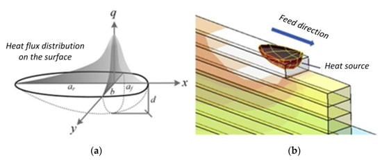
The front and rear halves of the heat flux densities are further discussed in the relevant literature [22][23][24][25][30,53,54,55], and the formulas are presented in Equations (3) and (4), respectively.
where af �� and ar �� are the lengths of the frontal ellipsoid and rear ellipsoid, respectively; b is the heat source width; c is the depth of the heat source, which is the heat source parameter; Q is the efficiency factor of energy input; and fr �� and ff �� are the distributing power factors for the rear and front heat source, respectively. The high-density electron beam heat source was modeled as a conical volumetric heat source with a Gaussian distribution or double ellipsoid volumetric heat source model, as given in Equation (5). The intensity distribution profile can be adopted and modified from the mathematical modeling [17][26][10,33].
where Q is the power generated per unit volume, h is the penetration depth, η is the heat source efficiency, Va �� is the accelerating voltage, Ib �� is the beam current, ∅e ∅� is the beam diameter, and x, y, and z are the local coordinates of a point on the part geometry.
ff+ fr=2��+ ��=2
Q=2h(1−zh)3×η×Va×Ibπ×∅2eexp(−2(x2+y2)∅2e)�=2ℎ(1−�ℎ)3×�×��×���×∅�2���(−2(�2+�2)∅�2)
Convective heat losses on the surface caused by the forced mechanism are ignored since the EBAM process is carried out in a vacuum. Radiation heat losses were considered from all outer free surfaces according to the Stefan–Boltzmann law as shown in Equation (6):
where ε� is the emissivity, σ is the Stefan–Boltzmann constant, Tsrf ���� is the surface temperature of the part, and T∞ �∞ is the ambient temperature (298 K).
qrad=εσ(T4srf−T4∞) ����=��(����4−�∞4)
Wu et al. [27][56] investigated the arc stability, bead formation, and metal transfer mechanisms during the fabrication of Ti6Al4V. From heat accumulation by gas tungsten WAAM, the effects of localized gas shielding and heat accumulation indicate the deposition constancy during the WAAM process control and component optimization. Others studied the indication of comprehensive thermal characteristics of a WAAM process and pointed out the thermal effects on the geometrical accuracy, process stability, and deposited part properties. The deposited beads’ temperature profile and the solidification parameters are examined using experimental and numerical simulation models that reflect the deposition process characteristics [28][29][30][31][22,57,58,59]. Inconsistent layer cross-sectional dimensions and undulated surface appearance are two types of defects observed in WAAM products. These are due to an inadequate heat input and nonlinear time-varying boundary conditions of the thermal effect in the molten pool [32][60]. Fluid flow and heat transfer models are usable to join process variables and parameters that affect the properties of printed parts. Both the arc pressure and the convective flow are the two main factors that govern the depth and width of penetration, respectively [33][61].
The summary of arc welding types and thermal distribution effects on the WAAM components is given in Table 1.
Table 1.
Some reviewed effects of thermal distribution on the specific study in the WAAM process.
| Arc Welding | Focus Area | Specific Area of the Study | Citation (Year) |
|---|---|---|---|
| EBM | Microstructure, macrostructure, and mechanical properties | Effect of heat input in WAAM process | [34][62] (2021) |
| GMAW | Geometric accuracy, productivity, and microstructure | Geometry regulation of thermoelectric cooling-aided bead in WAAM of thin-walled structures | [35][63] (2018) |
| CMT and C-GMAW mode |
Microstructure transformations and mechanical properties | Thermal effect on evolution of microstructure and mechanical properties in WAAM components | [36][64] (2022) |
| GT-WAAM | Influences of heat accumulation, surface oxidation, and bead geometries in building direction | Heat accumulation effects on the arc characteristics and metal transfer behavior in WAAM | [27][56] (2017) |
| GMA-AM | Multi-track depositions for different processing conditions for defect formation | Improving fluid flow and heat transfer model of WAAM | [33][61] (2021) |
| GT-WAAM | Heat accumulation effect on microstructure and mechanical properties of AM products | Heat impact on microstructure deposited and mechanical properties by WAAM | [37][15] (2018) |
| GMAW and PAW | Analysis of wall geometry, metallography, and mechanical properties. | Heat input effect on WAAM of Invar: microstructure and mechanical properties | [38][26] (2022) |
| GMAW-CMT | Assumption of thermomechanical analysis | Method of computing temperature and RS in WAAM component | [39][31] (2020) |
A high-temperature gradient near the melt pool leads to undesirable product dimensional distortion and deformation, which is the outcome of rapid thermal cycling. When the product is exposed to excessive strain due to thermal strain, it is more susceptible to fracture, which decreases the component life expectancy and increases the risk of early component failure [3][18]. The direction of deposition influences the residual strain and stress during the welding process of a single-pass multilayer [6][40][29,65]. The physical properties of the components made using WAAM depend on heat input during the printing process [13][48]. Similarly, physical properties such as the thermal conductivity and specific heat conductivity were increased with temperature while the density, viscosity, Young’s modulus, and yield strength decrease with increased temperature [41][66]. Moreover, thermomechanical simulation to predict the thermal flow and numerical analysis for metal addition during the deposition process are performed. The numerical analysis is validated with experimental investigation results by considering the effects of welding parameters such as the arc current, arc voltage, wire speed, welding speed, wire diameter, shielding gas, heat sources, and temperature fields, as studied and reported in [39][42][43][17,31,67].
In [18][44][51,68], it has been reported that a thin substrate and low interpass temperature are capable of minimizing the tensile RS in the WAAM products. The study also indicated that mechanical properties and microstructural characteristics are strongly dependent on the thermal history during printing. Likewise, significant temperature gradients, high heating and cooling rates, bulk temperature rises, and periodic thermal cycles cause variation in printed parts’ properties. One of the key factors in the WAAM process is thermal management to mitigate the accumulation of heat and cope with restrictions concerning geometry issues, the deposition cycle, and anisotropies in the mechanical properties [45][46][69,70]. Furthermore, a theoretical model was developed to optimize the heat input and the interlayer temperature for the deposition of each layer. In thin-walled structures built up in the WAAM process, molten pool solidification and bead geometry vary as wall height increases, mainly due to heat dissipation on the substrate. An active cooling system during the process using the technology of thermoelectric cooling is used to eliminate the variance in the dissipation of heat between the lower and upper layers [35][39][47][24,31,63]. The evolution of microstructure in the WAAM process depends on the material’s thermal history, which is estimated using FE modeling. Transformations of the microstructure are assessed with a diagram of continuous cooling transformation, and the microstructure is investigated with the use of scanning electron and optical microscopy. Similarly, the impact of temperature interpass on the hardness and microstructure was studied in [36][44][48][64,68,71] for AM80 HSLA steel, and the result revealed that a high interpass temperature leads to the development of martensite. During the WAAM process, heat accumulation results in the deposition of a multi-layer increase in the temperature preheat in the preceding built layer. These reasons lead to instabilities in the interlayer density, microstructure, mechanical properties, and geometry, which evolve differences in the material properties [49][50][72,73]. There are two types of temperature-measuring methods in the WAAM process: (1) contact (thermocouple) [17][22][26][51][10,30,33,74] and (2) non-contact measuring (infrared camera, pyrometrical methods, etc.,) [1][52][53][54][27,39,75,76].
2. Mechanical Modeling
Since the WAAM process has different thermal effects leading to varying mechanical properties of the printed parts, the process is examined in different building directions, which gave different results [3][18]. Additionally, variation in the substrate geometry has a significant effect on the molten pool geometry and heat transfer condition, which influence the welding for deposition of the WAAM process [55][56][1,77]. However, mechanical analysis to evaluate the stresses developed in the WAAM-printed products is carried out with a thermal load employed in finite element analysis (FEA) that caused RS and distortion. No significant variances were realized in either the mechanical or microstructural character succeeding heat treatments in air, in a vacuum, or in argon [57][58][59][60][78,79,80,81]. In the mechanical analysis, the clamping conditions (i.e., degrees of freedom constraints) have an important influence on the printed products [49][72].
The Lagrangian thermal model and nodal temperature results from the thermal analysis are used as thermal load inputs for the mechanical analysis [22][61][30,82]. Another investigation was performed in [22][30] using the Eulerian thermal model to calculate the steady-state temperature distributions, which are used as inputs to a 3D mechanical model for RS and distortion analysis. From the results of both the experimental and numerical studies, the temperature, distortion, and RS were compared and showed good agreement. Chen et al. [62][83] conducted a study of the superalloy (Ni-17Mo-7Cr) component fabricated with WAAM. The results showed stability in both tensile and hardness properties while a sharp reduction was perceived in the layers of the superficial surface. Thermal evolution is coupled to an elastoplastic mechanical boundary condition value problem that calculates the thermal stresses and distortions with Goldak thermal modeling approach. It was extensively modeled for accuracy by comparing the mechanical properties and thermal predictions with the equivalent experimental measurements with a non-linear transient function [4][23][41,53]. Hejripour et al. [63][84] studied on two parts built with WAAM, i.e., (1) wall and (2) tube from 2209 Duplex Stainless Steel. The results indicated that the slow rate of cooling for layers built at high temperatures caused austenite creation significantly in a ferrite matrix. The correlation between the developed thermal model for phase transformation and cooling rates is quite accurate to predict thermal cycles and weld zone profiles [45][64][65][66][7,69,85,86].
Even though WAAM technology is an energy-efficient manufacturing method for metal production, heat accumulation during deposition and associated mechanical changes result in RS, which was observed in the profiles across the cross-section of the printed components [67][68][25,87]. The mechanism of crack formation in a WAAM-manufactured Al-Zn-Mg-Cu alloy, which has high crack sensitivity, was studied using a combination of microstructure analysis and thermal-stress simulation [40][43][65,67]. The results indicated that increasing the deposition height increases the stress, which leads to crack propagation and the appearance of a macrocrack. In other studies, it has been reported that WAAM-manufactured super duplex stainless steel has both excellent corrosion resistance and mechanical properties [43][69][67,88]. In the studies, the microstructure of the wall deposited was carefully examined for variation in the mechanical properties. The results also revealed that the austenite/ferrite balance of phases in the wall body was fragmented by the overgrowing of the austenite phase. The anisotropic examination revealed that the ultimate tensile stress (UTS) and elongation appeared separately in the horizontal and vertical directions. The yield stress (YS) variables are rejected by the nitrogen work hardening result to a large extent.
WAAM technology with PAW has high deposition rates and can producing components of various sizes and yields with high mechanical performance. Similarly, two walls of Ti6Al4V were fabricated in a shielding argon atmosphere using WAAM-PAW to examine the deposition process, the growth in height per layer, the temperature deposition process, and the cooling times, which gave good results [45][69]. Three-dimensional thermoelastic–plastic transients and the thermomechanical multi-layer wall structure modeling approach are studied in [22][30]. The result of the study shows that temperature simulations and distortion expectations are proved by equating with the experimental results of laser scanners and thermocouples, while the RS is verified using neutron diffraction of strain scanner ENGIN-X. The response of the mechanical to the thermal history is examined by performing a 3D quasi-static incremental analysis.
The yield strength (σy��), elastic modulus (E), and coefficient of thermal expansion (α) are temperature-dependent, while other mechanical property values such as Poisson’s ratio are independent of temperature [70][89]. The physical and mechanical behavior of temperature-dependent properties such as the thermal conductivity, specific heat, and yield stress of SAE-AISI 1524 steel were studied in [71][90]. For materials such as SS 316 L, the behavior is supposed to be elastoplastic with a mix of kinematic and isotropic hardening (Chaboche-like model) [39][31]. Under the theory of small deformation, the total incremental strain can be disintegrated in elastic and inelastic forms. Equation (7) shows the formula for total deformation.
where Δεel, Δεth, Δεp, and Δεvp εvpΔ���, Δ��ℎ, Δ��, and Δ��� are, respectively, the elastic, thermal, plastic, and viscoplastic total incremental strains. The thermal strain is expressed in the absence of metallurgical transformations by Equation (8):
where α is the thermal expansion coefficient and Tref ���� is a reference temperature. In all three directions, the strains measured were combined to analyze the stress, supposing the directions measured are given by Hooke’s law with principal strain directions [22][30], as Equation (9).
where εx��, εy��, and εz �� are strains in the principal directions, E is the modulus of elasticity, and υ is Poisson’s ratio of the material.
Δεtot=Δεel+Δεth+Δεp+ΔεvpΔ����=Δ���+Δ��ℎ+Δ��+Δ���
εth=α(T)(T−Tref) ��ℎ=�(�)(�−����)
σx=E(1+υ)εx+Ev(1+υ)(1−2υ)(εx+εy+εz)��=�(1+�)��+��(1+�)(1−2�)(��+��+��)