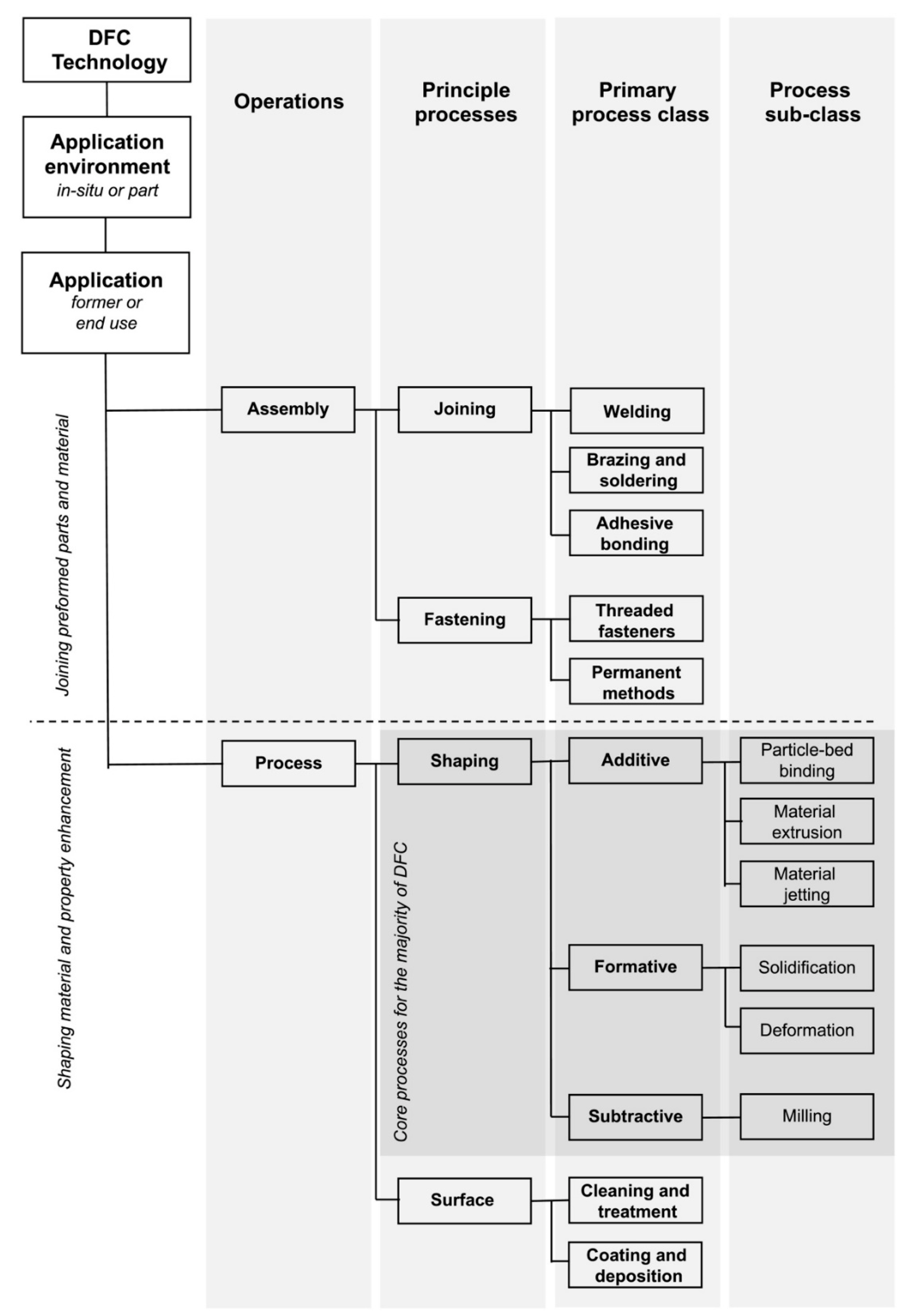
Extrusion-based 3D concrete printing (E3DCP) has been appreciated by academia and industry as the most plausible candidate for prospective concrete constructions.
- concrete extrusion
- 3D concrete printing
- ram extrusion
- extruder system design
1. Introduction
|
Mechanical System |
||
|---|---|---|
|
Principal shaping process |
Printing system |
Extruder system |
|
Positioning system |
||
|
Basic sub-process |
Basic fittings |
Mix proportioning system |
|
Primary mixing system |
||
|
Pumping system |
||
|
Curing system |
||
|
Advanced sub-process |
Advanced fittings |
Secondary mixing system |
|
Setting-/Fluid-on-demand system |
||
|
In-process reinforcement system |
||
|
Interlayer bonding enhancement system |
||
|
Finishing system |
||
|
Support placement system |
||
|
Monitoring and feedback system |
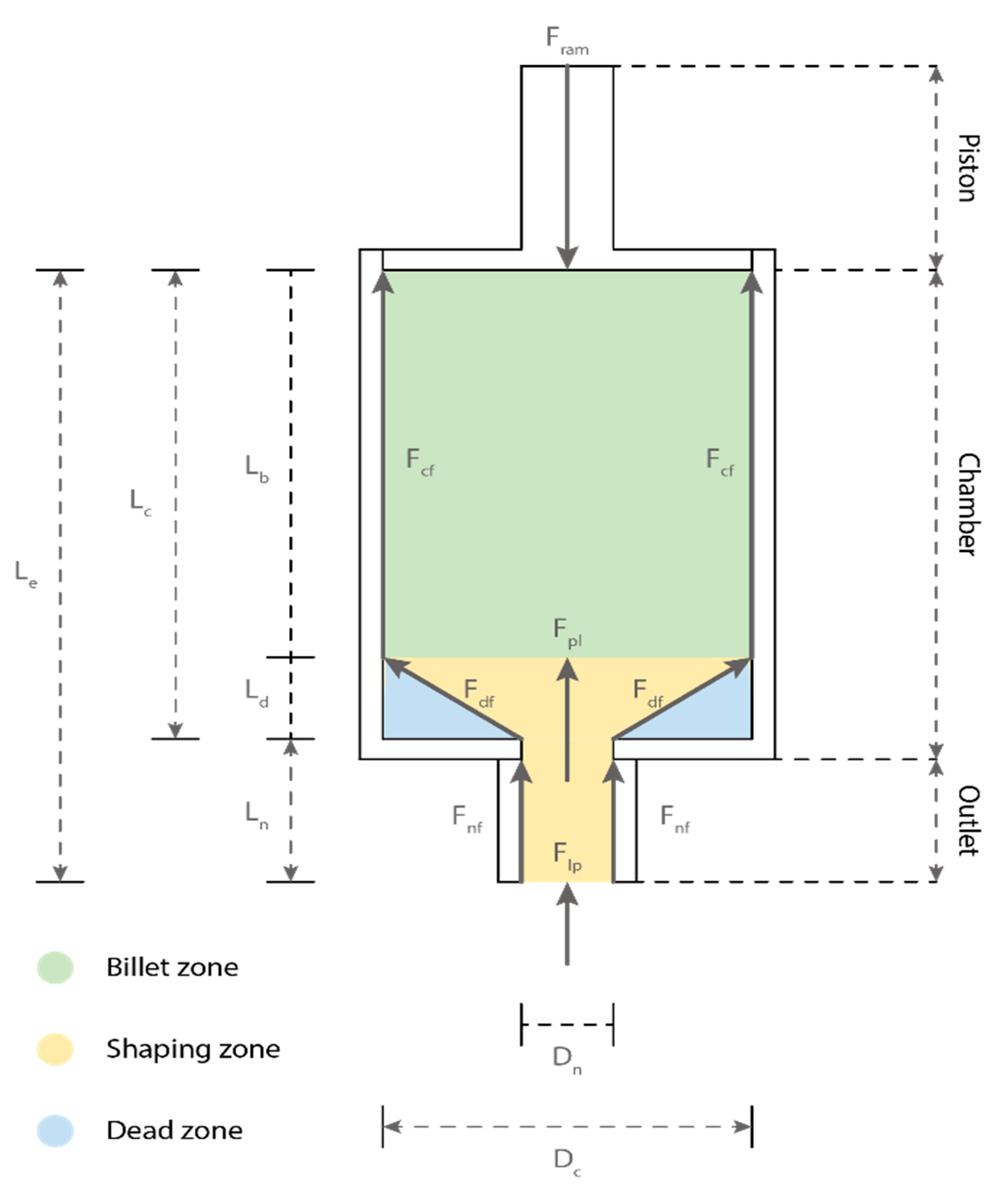
2. Extrusion Process and Extruder System
3. Deposition Process and Positioning System
Deposition is an additive process where a material is layered onto another layer of the material. During the E3DCP deposition process, the most important property is the buildability, which is defined as the ability of the deposited concrete filament to self-support and resist deformation without formworks [12,106][12][25]. The buildability stipulates that the concrete filament should provide sufficient resistance against plastic material failure, elastic buckling failure as well as excessive deformation [107][26]. However, the mechanical design of the positioning system has a relatively insignificant impact on the buildability compared to the material design. Therefore, the following section presents the mechanical design of the positioning system from a more practical perspective. Four types of E3DCP positioning systems can be identified: gantry system, robotic arm system, delta system, and swarm system. Each category is characterized by a different degree of freedom and build volume. The gantry system is the most common positioning system for E3DCP applications due to its ease of operational and cost-effectiveness. A gantry system is generally characterized by three DOFs of translational movements in x, y, z directions (Cartesian coordinate), but sometimes an additional rotational DOF can be added at the extruder to have four DOFs [108,109][27][28]. The build volume of the gantry system is constrained by the physical dimensions of the supporting frames in x, y and z directions, and it could range from desktop-scale for laboratory purpose to industrial-scale for construction purposes, see Table 2. To overcome the limited dimension of the gantry system, COBOD [3] has developed a flexible-dimension gantry concrete printer, BOD2, which could be assembled from multiple modular units of 2.5 × 2.5 × 2.5 to fit different construction scenarios. The contour crafting company [60][29] and IconBuild [110][30] retrofitted the gantry concrete printer with sliding rails to expand the workspace in one horizontal direction. From a practical standpoint, the robustness of the gantry system can sustain the on-site harsh conditions, however, it could be associated with considerable manual works in assembly and disassembly [62][31]. Additionally, the accuracy and repeatability of gantry printers are sufficient to complete large-scale E3DCP projects but they are not comparable to the robotic arm system. The robotic arm system printer generally consists of multiple links connecting altogether at rotary joints, which provides the system with more DOFs (six or more) and allows it to print more sophisticated designs. For example, Lim et al. [111][32] have pointed out that the staircase effect that typically associates with the extrusion-based 3DCP can be mitigated by adopting the curved-layer printing strategy instead of flat-layer printing. Concretely, in this approach, the extruder nozzle is positioned perpendicular to the target surface throughout the extrusion process so that the surface roughness and geometric accuracy can be improved. To fully exploit the potential of this approach, a position system with four or more DOFs is essential. Similarly, Gosselin et al. [112][33] recommended utilizing a six-axis robotic arm to realize the tangential continuity method for toolpath planning, which could produce non-planar layers with locally varying thicknesses, thereby unleashing the geometrical freedom of E3DCP to a greater extent. The approach has been used to 3D print multifunctional structures such as the thermal insulation wall and acoustic damping wall. Motamedi et al. [113][34] utilized a six-axis ABB robotic arm to print an overhang structure without support, which is only possible with the capability of the robotic arm to adjust the angle between the nozzle and printing surface. However, most industrial robotic arms (e.g., Kuka, ABB and Fanuc) have limited workspace. Once set-up, they can only print structures within a pie-shaped zone formed by the arm reach (generally less than 5 m), which will not suffice for conducting large-scale 3DCP projects. There have been various strategies proposed to extend the reach of the robotic arm: (1) installation of the extension arm at the extruder end [114][35]; (2) lifting of the robotic arms: the construction company Apis Cor [115][36] employed a crane to lift the pillar-like robotic arm printer after finishing printing tasks at one point; (3) provision of mobility to the robotic arm: the construction company Cybe [116][37] and the research team from NanYang Technical University [117][38] have both installed a mobile base underneath the robotic arm to enable theoretically infinite workspace in horizontal direction, and the research team from TU Dresden conceptualized the adaptation of a truck-mounted pump for E3DCP. However, such an approach imposes more strict requirements on the spatial localization of robotic arm, site conditions (e.g., flatness) as well as the weather conditions (e.g., low wind); (4) carrier system: ETH Zurich researchers [104][39] installed a six-axis ABB IRB 4600 robotic arm on a Güdel 3-axis gantry at ceiling to increase both the horizontal and vertical workspace, and the team from TsingHua University [118][40] provided an elevator platform to extend the workspace; and (5) multiple robotic arms: Zhang et al. [119][41] employed two mobile robotic arms to print structure simultaneously. Such an approach requires complex robotic path planning as well as collision checks before printing. Despite the multitudinous benefits of robotic arms, compared to the robustness of the gantry system, the delicacy of the robotic arm system has raised the suspicion of its suitability for rough on-site conditions, which explains why the majority of robotic arm printers are used under off-site conditions [62][31]. Apart from the mainstream gantry and robotic arm systems, there have been some innovative systems developed for E3DCP applications. For example, the construction company WASP [4] has customized a Delta 3D concrete printer called BigDelta with a dimension of 7 × 7 × 12 m. The printer consists of three cable-arms connected to joints at frame supports, and each arm could move independently in the y-direction, forming a navigation based on the polar coordinate. The German Fraunhofer Institute [120][42] also developed a similar delta 3D concrete printer based on eight cable arms. The delta system also has dimension constraints within the frame, and it also suffers from a higher risk of collision with the already printed parts compared to the gantry system [62][31]. The Institute for Advanced Architecture of Catalonia [121][43] has designed three swarm 3D concrete printers that could work collaboratively to produce structures: (1) the base robot, which deposits the first ten layers of concrete filaments to create a foundation; (2) the grip robot, which rests on the previously bult foundation and continues deposition to finish the structure; and (3) the vacuum robot, which climbs on the surface of the finished structure and deposits concrete filaments in z-direction. Theoretically, without considering the layer cycle time, such a swarm system can be used to construct large-scale concrete structures without dimensional limitation, especially in horizontal directions. Nonetheless, the technology remains relatively nascent and needs more exploration.|
Reference |
Positioning System |
Degree of Freedom |
Build Volume (L × W × H m)/Reach (m) |
|||||
|---|---|---|---|---|---|---|---|---|
|
Gantry |
3-axis | |||||||
|
Secondary mixing system (with secondary dosage) |
Static mixer |
• Higher (additives) 20 × 18 × 18 |
||||||
• Low | • The compatibility of different static mixers with different concrete materials. |
Gantry |
3-axis |
|||||
|
Dynamic mixer |
• Higher (additives) |
• Medium/High |
1.2 × 1.2 × 1.0 |
|||||
• The optimization of mechanical parameters, operational parameters, concrete material property, chemical admixture type and dosage and printing path. | ||||||||
|
Setting/Fluid on demand system |
Gantry |
Thermal heating 3-axis |
• Non 0.5 × 0.39 × 1.1 |
|||||
• Low/Medium/High * |
• Thermal gradients that can lead to non-uniform modifications of concrete properties. • Numerical modelling of the thermal effects during concrete extrusion. |
Robotic arm |
||||||
|
Electro/permanent magnet | 6-axis Fanuc R-2000iC/165F |
- |
||||||
• Higher material (magnetic particles) |
• Medium/High * |
• Compatibility of magnetic particles with concrete materials. • The guidelines for operational parameter control. |
||||||
|
Vibration |
Gantry |
• Non 3-axis |
• Medium/High * - |
|||||
• Impacts of vibration on the material extrudability. |
Gantry |
3-axis |
3.0 × 3.0 × 3.0 |
|||||
|
In-process reinforcement system |
Entrainment |
• Higher (reinforcements) |
• Medium/High * |
• The control of the feed-in speed of the reinforcement materials. • The correct alignment of the reinforcement with respect to the concrete layer cross-sectional centroid to prevent anisotropic properties and ensure uniform covering |
Robotic arm |
6-axis KUKA KR60 HA |
||
|
Placing between layers |
• High/High * |
• Concrete materials with appropriate rheological properties to seal the horizontal weak interface which would be otherwise susceptible for moisture and chemical invasions. • Precise positionings of the reinforcement |
- |
|||||
|
Gantry |
3-axis |
|||||||
|
Cross-layer encasement |
• High/High * | 1.8 × 1.8 × 1.5 |
||||||
• Concrete materials with appropriate rheological properties to seal both the vertical and horizontal weak interfaces |
• Precise positionings of the reinforcement in terms of the centerline alignments. |
Cross-layer penetration Gantry |
• High/High * 4-axis |
• Precise positionings of the reinforcement in terms of the spacing and centerline alignments. 9 × 4.5 × 2.8 |
||||
|
Gantry |
3-axis |
0.15 × 0.15 × 0.12 |
||||||
|
Interlayer bonding enhancement system |
Bonding agents |
• Higher (bonding agents) |
• Medium |
• Compatibility of the bonding agents with the concrete materials. |
Robotic arm |
6-axis Denso |
- |
|
|
Physical |
• Non |
• Medium/High |
• The implementations of the physical means without affecting the extrusion process. |
Robotic arm |
||||
|
Finishing system |
• Non |
6-axis FANUC R-2000iC/165F |
- |
|||||
• High |
• More precise precision according to the printing path |
|||||||
|
Support placement system |
Gantry |
3-axis |
- |
|||||
• Higher (supports) |
• High |
• Precise positions of the supports. • The effects of pause on the printing time and open time of the concrete materials. |
Robotic arm and gantry |
6-axis ABB IRB 4600 robotic arm hanging on a Güdel 3-axis gantry |
- |
|||
|
Monitoring and feedback system |
• Non |
• Medium/High |
• The monitoring itself is not complex, however, the real-time analysis, feedback and adjustment can significantly increase the complexity |
Gantry |
3-axis |
10.36 × 2.74 × 3.05 |
||
|
Gantry |
3-axis |
0.40 × 0.30 × 0.30 |
||||||
|
Gantry |
4-axis |
- |
||||||
|
Gantry |
4-axis |
- |
||||||
|
[3] |
Gantry |
3-axis |
Infinite × 14.6 × 8.1 |
|||||
|
Gantry |
3-axis |
Infinite × 8.53 × 2.59 |
||||||
|
Robotic arm |
6-axis |
2.65–3.50 |
||||||
|
Robotic arm |
7-axis |
Infinite × Infinite × ~3 |
||||||
|
Delta system |
- |
17 × 12 × 5 |
||||||
|
[4] |
Delta system |
- |
7 × 7 × 12 m |
|||||
4. Advanced Sub-Processes and Advanced Fittings
According to the literature the authors have reviewed, the advanced fittings can be classified as the secondary mixing, setting-/fluid-on-demand, in-process reinforcement, interlayer bonding enhancement, finishing, support placement and monitoring, and feedback processes. The inclusions of the advanced sub-processes within the printing system generally increase the energy, machine and maintenance costs (in the passive systems, the energy increase may be insignificant). Additionally, they may increase the energy and material costs as well as the technical complexity of the overall system, as shown in Table 3.|
Advanced Fittings |
Material Cost |
Technical Complexity * |
||
|---|---|---|---|---|
Low, when the system is a passive system; medium, when the system is automated but independent of the printing path and programming; high, when the system needs to be integrated and programed with the printing path definition to perform its intended task; high *, when the system could be coupled with the printing path to achieve functional-graded materials.
References
- Buswell, R.; da Silva, W.L.; Bos, F.; Schipper, H.; Lowke, D.; Hack, N.; Kloft, H.; Mechtcherine, V.; Wangler, T.; Roussel, N. A process classification framework for defining and describing Digital Fabrication with Concrete. Cem. Concr. Res. 2020, 134, 106068.
- XtreeE. Available online: https://xtreee.com/en/ (accessed on 3 August 2022).
- COBOD. Available online: www.cobod.com (accessed on 3 August 2022).
- WASP. BigDelta 3D Concrete Printer. Available online: https://www.3dwasp.com/en/giant-3d-printer-bigdelta-wasp-12mt/ (accessed on 3 August 2022).
- Sika Group. 2020. Available online: https://www.sika.com/en/knowledge-hub/3d-concrete-printing.html (accessed on 3 August 2022).
- Lowke, D.; Vandenberg, A.; Pierre, A.; Thomas, A.; Kloft, H.; Hack, N. Injection 3D concrete printing in a carrier liquid—Underlying physics and applications to lightweight space frame structures. Cem. Concr. Compos. 2021, 124, 104169.
- Lloret, E.; Shahab, A.R.; Linus, M.; Flatt, R.J.; Gramazio, F.; Kohler, M.; Langenberg, S. Complex concrete structures. Comput. Des. 2015, 60, 40–49.
- Hack, N.; Kloft, H. Shotcrete 3D Printing Technology for the Fabrication of Slender Fully Reinforced Freeform Concrete Elements with High Surface Quality: A Real-Scale Demonstrator. In DC 2020: Second RILEM International Conference on Concrete and Digital Fabrication; Springer International Publishing: Berlin/Heidelberg, Germany, 2020; Volume 28, pp. 1128–1137.
- Wangler, T.; Pileggi, R.; Gürel, S.; Flatt, R.J. A chemical process engineering look at digital concrete processes: Critical step design, inline mixing, and scaleup. Cem. Concr. Res. 2022, 155, 106782.
- Perrot, A.; Rangeard, D.; Naidu, V.; Mechtcherine, V. Extrusion of cement—Based materials—An overview. RILEM Tech. Lett. 2019, 2018, 91–97.
- Li, Z.; Hojati, M.; Wu, Z.; Piasente, J.; Ashrafi, N.; Duarte, J.P.; Nazarian, S.; Bilén, S.G.; Memari, A.M.; Radlińska, A. Fresh and Hardened Properties of Extrusion-Based 3D-printed Cementitious Materials: A Review. Sustainability 2020, 12, 5628.
- Roussel, N. Rheological requirements for printable concretes. Cem. Concr. Res. 2018, 112, 76–85.
- Zhang, C.; Nerella, V.N.; Krishna, A.; Wang, S.; Zhang, Y.; Mechtcherine, V.; Banthia, N. Mix design concepts for 3D printable concrete: A review. Cem. Concr. Compos. 2021, 122, 104155.
- Lu, B.; Weng, Y.; Li, M.; Qian, Y.; Leong, K.F.; Tan, M.J.; Qian, S. A systematical review of 3D printable cementitious materials. Constr. Build. Mater. 2019, 207, 477–490.
- Blackburn, S.; Szymiczek, M. Extrusion. In Encyclopedia of Materials: Technical Ceramics and Glasses; Pomeroy, M., Ed.; Elsevier: Oxford, UK, 2021; pp. 162–178.
- Buswell, R.A.; De Silva, W.R.L.; Jones, S.Z.; Dirrenberger, J. 3D printing using concrete extrusion: A roadmap for research. Cem. Concr. Res. 2018, 112, 37–49.
- Basterfield, R.; Lawrence, C.; Adams, M. On the interpretation of orifice extrusion data for viscoplastic materials. Chem. Eng. Sci. 2005, 60, 2599–2607.
- Zhou, X. Characterization of rheology of fresh fiber reinforced cementitious composites through ram extrusion. Mater. Struct. 2004, 38, 17–24.
- Perrot, A.; Rangeard, D.; Mélinge, Y. Prediction of the ram extrusion force of cement-based materials. Appl. Rheol. 2014, 24, 34–40.
- Perrot, A.; Lanos, C.; Estellé, P.; Melinge, Y. Ram extrusion force for a frictional plastic material: Model prediction and application to cement paste. Rheol. Acta 2006, 45, 457–467.
- Nair, S.; Panda, S.; Tripathi, A.; Neithalath, N. Relating print velocity and extrusion characteristics of 3D-printable cementitious binders: Implications towards testing methods. Addit. Manuf. 2021, 46, 102127.
- Nair, S.A.; Panda, S.; Santhanam, M.; Sant, G.; Neithalath, N. A critical examination of the influence of material characteristics and extruder geometry on 3D printing of cementitious binders. Cem. Concr. Compos. 2020, 112, 103671.
- Percoco, G.; Arleo, L.; Stano, G.; Bottiglione, F. Analytical model to predict the extrusion force as a function of the layer height, in extrusion based 3D printing. Addit. Manuf. 2020, 38, 101791.
- Mechtcherine, V.; Bos, F.; Perrot, A.; da Silva, W.L.; Nerella, V.; Fataei, S.; Wolfs, R.; Sonebi, M.; Roussel, N. Extrusion-based additive manufacturing with cement-based materials—Production steps, processes, and their underlying physics: A review. Cem. Concr. Res. 2020, 132, 106037.
- Perrot, A.; Rangeard, D.; Pierre, A. Structural built-up of cement-based materials used for 3D-printing extrusion techniques. Mater. Struct. 2015, 49, 1213–1220.
- Kruger, J.; Zeranka, S.; van Zijl, G. 3D concrete printing: A lower bound analytical model for buildability performance quantification. Autom. Constr. 2019, 106, 102904.
- Suiker, A.; Wolfs, R.; Lucas, S.; Salet, T. Elastic buckling and plastic collapse during 3D concrete printing. Cem. Concr. Res. 2020, 135, 106016.
- Wolfs, R.J.M.; Bos, F.P.; Salet, T.A.M. Hardened properties of 3D printed concrete: The influence of process parameters on interlayer adhesion. Cem. Concr. Res. 2019, 119, 132–140.
- Contour Crafting. Offering Automated Construction of Various Types of Structures. Available online: http://contourcrafting.com/building-construction (accessed on 6 August 2022).
- IconBuild. 2020. Available online: https://www.iconbuild.com/technology (accessed on 6 August 2022).
- Mechtcherine, V.; Nerella, V.N.; Will, F.; Näther, M.; Otto, J.; Krause, M. Large-scale digital concrete construction – CONPrint3D concept for on-site, monolithic 3D-printing. Autom. Constr. 2019, 107, 102933.
- Lim, S.; Buswell, R.A.; Valentine, P.J.; Piker, D.; Austin, S.A.; De Kestelier, X. Modelling curved-layered printing paths for fabricating large-scale construction components. Addit. Manuf. 2016, 12, 216–230.
- Gosselin, C.; Duballet, R.; Roux, P.; Gaudillière, N.; Dirrenberger, J.; Morel, P. Large-scale 3D printing of ultra-high performance concrete—A new processing route for architects and builders. Mater. Des. 2016, 100, 102–109.
- Motamedi, M.; Oval, R.; Carneau, P.; Baverel, O. Supportless 3D Printing of Shells: Adaptation of Ancient Vaulting Techniques to Digital Fabrication. In DMSB 2019: Impact: Design with All Senses; Springer International Publishing: Berlin/Heidelberg, Germany, 2020.
- Watson, N.D.; Meisel, N.A.; Bilén, S.G.; Duarte, J.; Nazarian, S. Large-scale additive manufacturing of concrete using a 6-axis robotic arm for autonomous habitat construction. In Solid Freeform Fabrication 2019: Proceedings of the 30th Annual International Solid Freeform Fabrication Symposium—An Additive Manufacturing Conference, SFF, Austin, Texas, USA, 12–14 August 2019; University of Texas at Austin: Austin, Texas, USA, 2019; pp. 1583–1595. Available online: https://www.scopus.com/inward/record.uri?eid=2-s2.0-85095963939&partnerID=40&md5=ec58c652b9bb4aafc527483f8c7d5c71 (accessed on 9 August 2022).
- Apis Cor. Available online: https://apis-cor.com/ (accessed on 17 March 2023).
- Cybe Construction. Available online: https://cybe.eu/technology/3d-printers/ (accessed on 6 August 2022).
- Tiryaki, M.E.; Zhang, X.; Pham, Q.-C. Printing-while-moving: A new paradigm for large-scale robotic 3D Printing. In Proceedings of the 2019 IEEE/RSJ International Conference on Intelligent Robots and Systems (IROS), Macau, China, 3–8 November 2019; pp. 2286–2291.
- Anton, A.; Reiter, L.; Wangler, T.; Frangez, V.; Flatt, R.J.; Dillenburger, B. A 3D concrete printing prefabrication platform for bespoke columns. Autom. Constr. 2020, 122, 103467.
- Archdaily. 3D Printing Concrete House/Professor XU Weiguo’s Team from the Tsinghua University School of Architecture. Available online: https://www.archdaily.com/949068/3d-printing-concrete-house-for-the-low-income-families-in-africa-professor-xu-weiguos-team-from-thad (accessed on 9 August 2022).
- Zhang, X.; Li, M.; Lim, J.H.; Weng, Y.; Tay, Y.W.D.; Pham, H.; Pham, Q.-C. Large-scale 3D printing by a team of mobile robots. Autom. Constr. 2018, 95, 98–106.
- Fraunhofer. Paralleler Seilroboter zur Handhabung in Allen Größen (Parallel Cable Robot for Handling in Any Size); Data Sheet 300/354 02.2017. 2017. Available online: https://www.ipa.fraunhofer.de/content/dam/ipa/de/documents/Kompetenzen/Roboter--und-Assistenzsysteme/Produktblatt_Paralleler_Seilroboter.pdf (accessed on 9 August 2022).
- Institute for Advanced Architecture of Catalonia. SMALL ROBOTS PRINTING LARGE-SCALE STRUCTURES. Available online: https://iaac.net/project/minibuilders/ (accessed on 9 August 2022).
- Ji, G.; Ding, T.; Xiao, J.; Du, S.; Li, J.; Duan, Z. A 3D Printed Ready-Mixed Concrete Power Distribution Substation: Materials and Construction Technology. Materials 2019, 12, 1540.
- Weng, Y.; Li, M.; Tan, M.J.; Qian, S. Design 3D printing cementitious materials via Fuller Thompson theory and Marson-Percy model. Constr. Build. Mater. 2018, 163, 600–610.
- Ma, G.; Li, Z.; Wang, L. Printable properties of cementitious material containing copper tailings for extrusion based 3D printing. Constr. Build. Mater. 2018, 162, 613–627.
- Comminal, R.; da Silva, W.R.L.; Andersen, T.J.; Stang, H.; Spangenberg, J. Modelling of 3D concrete printing based on computational fluid dynamics. Cem. Concr. Res. 2020, 138, 106256.
- Lim, J.H.; Panda, B.; Pham, Q.-C. Improving flexural characteristics of 3D printed geopolymer composites with in-process steel cable reinforcement. Constr. Build. Mater. 2018, 178, 32–41.
- Ding, T.; Xiao, J.; Zou, S.; Wang, Y. Hardened properties of layered 3D printed concrete with recycled sand. Cem. Concr. Compos. 2020, 113, 103724.
- Gomaa, M.; Jabi, W.; Veliz Reyes, A.; Soebarto, V. 3D printing system for earth-based construction: Case study of cob. Autom. Constr. 2021, 124, 103577.
- Bai, G.; Wang, L.; Ma, G.; Sanjayan, J.; Bai, M. 3D printing eco-friendly concrete containing under-utilised and waste solids as aggregates. Cem. Concr. Compos. 2021, 120, 104037.
- Bos, F.; Wolfs, R.; Ahmed, Z.; Salet, T. Additive manufacturing of concrete in construction: Potentials and challenges of 3D concrete printing. Virtual Phys. Prototyp. 2016, 11, 209–225.
- Baz, B.; Aouad, G.; Kleib, J.; Bulteel, D.; Remond, S. Durability assessment and microstructural analysis of 3D printed concrete exposed to sulfuric acid environments. Constr. Build. Mater. 2021, 290, 123220.
- Panda, B.; Paul, S.C.; Hui, L.J.; Tay, Y.W.D.; Tan, M.J. Additive manufacturing of geopolymer for sustainable built environment. J. Clean. Prod. 2017, 167, 281–288.
- Andersen, S.; Da Silva, W.R.L.; Paegle, I.; Nielsen, J.H. Numerical Model Describing the Early Age Behavior of 3D Printed Concret—Work in Progress. In Second RILEM International Conference on Concrete and Digital Fabrication: Digital Concrete 2020; Springer International Publishing: Berlin/Heidelberg, Germany, 2020; pp. 175–184.
- Carneau, P.; Mesnil, R.; Ducoulombier, N.; Roussel, N.; Baverel, O. Characterisation of the Layer Pressing Strategy for Concrete 3D Printing. In DC 2020: Second RILEM International Conference on Concrete and Digital Fabrication; Springer International Publishing: Berlin/Heidelberg, Germany, 2020; Volume 28, pp. 185–195.
- Diggs-McGee, B.N.; Kreiger, E.L.; Kreiger, M.A.; Case, M.P. Print time vs. elapsed time: A temporal analysis of a continuous printing operation for additive constructed concrete. Addit. Manuf. 2019, 28, 205–214.
- Bester, F.A.; Van Den Heever, M.; Kruger, P.J.; Zeranka, S.; Van Zijl, G.P.A.G. Benchmark structures for 3D concrete printing. In Proceedings of the Fib Symposium 2019: Concrete—Innovations in Materials, Design and Structures, Krakow, Poland, 27–29 May 2019; pp. 305–312.
- Panda, B.; Unluer, C.; Tan, M.J. Extrusion and rheology characterization of geopolymer nanocomposites used in 3D printing. Compos. Part B Eng. 2019, 176, 107290.