Your browser does not fully support modern features. Please upgrade for a smoother experience.
Please note this is a comparison between Version 1 by Ajay K Dalai and Version 3 by Ajay K Dalai.
With an increase in the global population and the subsequent rise in energy demands and waste generation, the rate of CO2 release is at a much faster rate than its recycling through photosynthesis or fixation, which increases its net accumulation in the atmosphere. A large amount of CO2 is emitted into the atmosphere from various sources such as the combustion of fossil fuels in power plants, vehicles and manufacturing industries. Thus, carbon capture plays a key role in the race to achieve net zero emissions, paving a path for a decarbonized economy.
- carbon dioxide
- fossil fuels
- greenhouse gas
- sequestration
- storage
- utilization
1. Introduction
CO2 capture technologies are of global importance because CO2 emissions from fossil fuels have significantly threatened the economy, the environment, natural ecosystems and human health. Advances in carbon capture and utilization technology can dramatically reduce CO2 emissions and lead the path towards net zero and achieve several United Nations Sustainable Development Goals, especially Goal 6 (Clean Water and Sanitation), Goal 7 (Affordable and Clean Energy), Goal 9 (Industry, Innovation and Infrastructure), Goal 11 (Sustainable Cities and Communities), Goal 12 (Responsible Consumption and Production) and Goal 13 (Climate Action).
Carbon capture, storage and utilization can be achieved in four phases. The first step is the removal of CO2 from the point source. Flue gases are emitted from industrial plants and are considered the point source through physical and chemical absorption, adsorption, membrane-based separation and other emerging technologies [1][2][20,21]. Compressed CO2 in liquid form is easy to store and transport. CO2 can be stored permanently underground by injecting it into porous rocks or under ocean beds through geo-sequestration [3][22]. The selection of locations depends on the abundance of porous rock in the ground. The injected CO2 fills out the pores inside the rocks and is detained there from above by covering an impermeable layer. This technique is very similar to the storage phenomenon of oil and gas underground. Both onshore and offshore basins can be used for the geological storage of CO2. The utilization of captured CO2 is intended to convert the captured CO2 into valuable chemicals, enhance oil recovery and recover untapped oil or alkaline remediation. The combusted exhaust gas is used as the feedstock material for utilization. CO2 is used in food and beverage processing and for producing synthetic or hydrocarbon fuels in combination with hydrogen.
Figure 1 illustrates the main pathways for CO2 capture and utilization. The main methods for CO2 capture are pre-combustion, post-combustion, oxyfuel combustion and direct air capture. The available technologies for CO2 capture are adsorption, membrane separation, chemical looping, cryogenic distillation and hydrate-based separation. The captured CO2 can be utilized to produce clean fuels, chemicals and valuable minerals, enhanced oil recovery and other direct uses. Table 1 summarizes the principles and promising aspects of some CO2 utilization technologies.
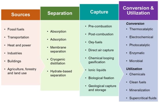
Figure 1.
Common routes for CO
2
separation, capture and utilization.
Table 1.
Summary of CO
2
utilization processes.
| Pathway | Principle | Benefits |
|---|---|---|
| Biochar production | Waste biomass (agricultural, woody, algal and municipal solid waste) can be thermochemically and hydrothermally carbonized to produce biochar. |
|
| Algae cultivation | Algae utilize CO2 directly from the atmosphere for photosynthesis. |
|
| Production of building materials | CO2 can be mineralized into carbonates and limestones. |
|
| Enhanced oil recovery | Injection of captured CO2 into oil reservoirs along with water. |
|
| Chemicals production | CO2 captured from industrial flue gases and the atmosphere can be converted into valuable chemicals. |
|
| Clean fuel production | CO2 captured from industrial flue gases and the atmosphere can be converted into valuable biofuels. |
|
2. Pre-Combustion
ItFigure 2 graphis important to have an cally represents the interconnection between ed mechanisms of pre-combustion, post-combustion, oxy-fuel combustion and other industrial CO2 capture processes [8][27]. Pre-combustion takes place before the combustion process where the fuel is gasified in the presence of oxygen and steam, resulting in syngas production. CO present in the syngas is converted into CO2 through the water–gas shift reaction and captured before combustion, whereas H2 present in the syngas is used as a direct fuel in the gas turbines [9][28]. The pre-combustion capture technique uses both physical and chemical methods to capture CO2 from processed syngas. Chemical absorbents such as carbonates and physical solvents such as methanol and polypropylene glycol are generally used for CO2 capture on a commercial scale [10][29]. The pre-combustion route can proportionately reduce costs by 38–45% and 21–24% compared to the post-combustion and oxy-combustion routes [11][30]. However, owing to the modernization of existing facilities, an additional cost is involved regarding the setup of the process units such as gasifiers and water–gas shift reactors, which limits commercialization.
Dakota Gasification Company’s Great Plains Synfuels Plant in North Dakota, USA, produces 150 million ft
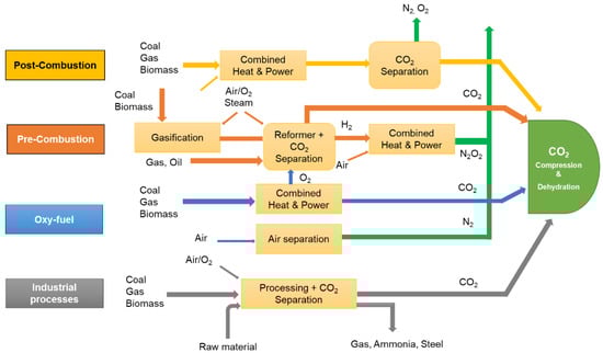
Figure 2. Graphical illustration of post-combustion, pre-combustion and oxy-fuel carbon capture technologies (Adapted from IPCC [27]).
Dakota Gasification Company’s Great Plains Synfuels Plant in North Dakota, USA, produces 150 million ft3 of syngas from the gasification of about 18,000 tons of lignite coal [12]. The company also implements the methanol-based Rectisol process at an annual capacity of 3 mt-CO of syngas from the gasification of about 18,000 tons of lignite coal [31]. The company also implements the methanol-based Rectisol process at an annual capacity of 3 mt-CO2 [13]. About 155 million ft [32]. About 155 million ft3 of CO2 is compressed and sent to a Canadian oil field in Weyburn-Midale fields located in southeastern Saskatchewan via a 320 km pipeline for enhanced oil recovery [14][15]. Mississippi Power’s Kemper County energy facility intended to perform gasification of lignite coal and store its captured carbon emissions pre-combustion of the syngas. However, the project was shelved in 2017 due to project delays and increased costs [16]. According to the literature, although there are some pilot-scale studies of pre-combustion carbon capture, there is a lack of full-scale pre-combustion facilities at a global scale [13]. is compressed and sent to a Canadian oil field in Weyburn-Midale fields located in southeastern Saskatchewan via a 320 km pipeline for enhanced oil recovery [33,34]. Mississippi Power’s Kemper County energy facility intended to perform gasification of lignite coal and store its captured carbon emissions pre-combustion of the syngas. However, the project was shelved in 2017 due to project delays and increased costs [35]. According to the literature, although there are some pilot-scale studies of pre-combustion carbon capture, there is a lack of full-scale pre-combustion facilities at a global scale [32].
3. Post-Combustion and Oxy-Fuel Technologies
In the post-combustion technique, CO2 is removed after the combustion process from the flue gas released from coal-fired power plants and other manufacturing industries. The post-combustion technologies are the favored option for modifying existing power plants. The most common pathways in post-combustion carbon capture are membrane separation, chemical absorption, chemical looping and physical adsorption. Examples of industries implementing post-combustion carbon capture, especially amine-based processes, include Mitsubishi Heavy Industries Ltd. (Tokyo, Japan), HTC Purenergy (Canada), Aker Carbon Capture (Norway) and Kerr-McGee/ABB Lummus (USA) [13][32]. AES Warrior Run Power Plant in Maryland, USA, generates over 180 MW of energy from coal, and 4–6% of the captured CO2 (via amine-based adsorption process) is sold to food and beverage industries [17][36]. Linde has partnered with BASF in implementing post-combustion carbon capture and using amine as a solvent to scrub CO2 from the flue gas stream [18][37]. Linde’s post-combustion carbon capture plant in Wilsonville, USA, can process 9100 Nm3/h of flue gas and capture 42 tons/day of CO2 [19][38]. Similarly, Linde’s post-combustion carbon capture plant in Niederaussem, Germany, processes 1552 Nm3/h of flue gas and captures 7.2 tons/day of CO2 [19][38]. Recently, ExxonMobil has announced its partnership with National Renewable Energy Laboratory (NREL) and National Energy Technology Laboratory (NETL) to advance its collaboration in research and development relating to biofuels, process intensification, life-cycle assessment and carbon capture [20][39].
The oxy-fuel technique is like the post-combustion process, except that the fuel is fired in the presence of oxygen. It makes the flue gas more concentrated with CO2, which enhances its capturing process [10][29]. Using an oxy-fuel boiler, the Linde/BASF plant in Schwarze Pumpe, Germany, can capture 240 tons/day of CO2 from a 7000 Nm3/h flue gas stream [19][38]. NET Power LLC in the USA has successfully demonstrated a low-cost and emission-free oxy-fuel combustion facility in La Porte, Texas, which is a 50 MW natural gas power plant and the only large-scale supercritical CO2-based plant in the world [21][40].
4. Direct Air Capture
In the air, CO2 is found in a much lighter form than that found in industrial flue gases. Currently, there are two approaches to removing CO2 from the air such as solid and liquid direct air capture (DAC). Solid DAC technology uses solid sorbent materials which can hold CO2 by chemical adsorption. The stored concentrated CO2 in the filter can be recovered by heating or keeping it in a vacuum system for further storage or use. In the liquid DAC systems, the air is passed through a solution of hydroxide, which strips the CO2. The captured CO2 can then be stored in the deep geological rocks or ocean beds by injection under high pressure [22][41]. Although the DAC process is expensive, there are some benefits of the DAC process such as a lower land and water requirement and a low bulk transportation cost of captured CO2. The cost of operation depends on the bestowing technology approach, whether the CO2 will be stored geologically or be cast off directly under low pressure.
Strong bases or aqueous hydroxide solutions such as KOH and NaOH are used as solvents to chemisorb CO2 for DAC technologies [23][42]. The chemisorbed CO2 is then converted into carbonates and bicarbonates. Monoethanolamine is an aqueous amine solvent that is found effective for scrubbing flue gas by interacting with CO2 and converting it into carbamate anions that could later hydrolyze to bicarbonate [24][43]. One of the main challenges encountered in amine-solvent-based DAC is the loss of solvent due to evaporation as large volumes of air or flue gases are blown over the aqueous solution and potential amine degradation over the longer reaction period [25][44]. Some mitigation strategies include the following: (i) using less volatile amine solvents or amine derivatives such as amino acids [26][45] and (ii) using porous solid supports such as silica, organic polymers and metal–organic frameworks to immobilize reactive amine groups [27][46]. It has also been reported that higher concentrations of amine can lower energy consumption and equipment size, thereby reducing the operating expenditure of the carbon sequestration process [13][32].
Although the DAC process is relatively expensive, it has some major benefits such as a lower land and water requirement and a low bulk transportation cost of captured CO2. The cost of operation depends on the technology approach, i.e., whether CO2 will be stored geologically or cast off directly under low pressure. Freitas et al. [28][47] demonstrated a conceptual nano-factory-based molecular filter powered by solar energy at a low cost of U.S. $18.3/ton of CO2. In another study by Kiani et al. [29][48], the projected cost for DAC captured CO2 per ton was estimated to be U.S. $114 at a scale of 1 MtCO2 per year.
Climeworks AG, a Switzerland-based company, is one of the world’s first commercial DAC plants [30][49]. The design uses an adsorption–desorption process on alkaline-functionalized adsorbents. The adsorption of CO2 takes place at ambient conditions while the temperature-vacuum swing process is used for desorption. It also uses an amine-supported cellulose fiber-based filter to adsorb CO2 molecules. Produced CO2 in this process is >99.8% pure, and simultaneously H2O is released as a byproduct [31][50]. In 2017, the plant was able to capture 900 tons of CO2 per annum. The technology requires 2000 KWh of energy per ton of CO2, and the capture process is powered by renewable energy sources. The cost of CO2 removal and permanent storage via mineralization is expected to be less than U.S. $100/ton of CO2 over the years [32][51]. Furthermore, Carbon Engineering in British Columbia, Canada, uses high-temperature aqueous solutions for DAC [33][52]. Global Thermostat in Colorado, USA is a DAC company, which can remove CO2 from the atmosphere at the point source emissions [34][53].
5. Chemical Looping Combustion and Gasification
In the first approach, limestone (CaCO3) can be taken as sorbents to preserve CO2 from the gas mixture. When solid CaCO3 is heat treated at around 850 °C to 950 °C in a calciner, it decomposes into gaseous CO2 and solid CaO. The pure stream of CO2 is then collected and purified for storage or use. In another approach, CO2 can be seized through the liquid solvent or other separation methods. Under the absorption-based approach, once the CO2 is captured by the solvent, then CO2 can be removed in high-purity form by heating. This technology is widely used in capturing CO2 for use in the food and beverage industry. Strong bases aqueous solution of soda lime, NaOH, KOH and LiOH can remove CO2 by chemical reaction. LiOH was used in the canister of the spacecraft of the historic manned lunar landing mission, Apollo 11 in 1969, to remove CO2 from the atmosphere [35][54].
Clean H2 can be produced by applying oxidation and reduction-based chemical looping technology [36][55]. In this technology, coal or syngas-based chemical looping systems use looping particles of metal in contact with oxygen from the combustion air to form metal oxide. There are two steps of separation taking place in two fuel reactors. In the first step, the oxidation of fossil fuels such as coal or biomass is accomplished, and in the second step, gas separation is performed to produce high-purity H2. The exodus stream contains CO2 along with water after condensing out pure CO2. The advantage of this technique is that it does not require cleaning up the fuel gas before separating H2. In addition, at high pressure, the chemical looping system produces a stream of CO2 which eliminates a costly pressurization step.
Owing to the properties of electrophilicity in carbon atoms, organic–inorganic bases with strong nucleophilic atoms can be extensively used in capturing CO2. Hence, the bases interact directly with CO2 as a proton acceptor. The harvested CO2 could be used for the synthesis of valuable chemicals. Pure and high-pressure CO2 is needed in most processes of CO2 conversion to value-added fuels, chemicals and products manufacturing.
Chemical looping combustion and gasification is emerging as a new method for CO2 capture during fuel processing; it also has some limitations that impede scaling up. Some of the bottlenecks are the following: (i) high endothermicity of combustion and gasification; (ii) high cost of oxygen required for largescale combustion and gasification; (iii) operating expenditures for maintenance of combustion and gasification reactors when dealing with heterogeneous feedstocks; (iv) agglomeration, sintering, low lifetime and high cost of applied catalysts; (v) sensitivity of operating conditions and (vi) limited choices for oxygen carriers [37][56]. To address these issues, in situ gasification chemical looping combustion has emerged [38][57]. In this new approach, the fuel emissions such as CO2 and H2O are recirculated to play as gasifying agents. Hence, the volatile vapors and syngas generated from gasification are oxidized in a gas–solid reaction in the presence of an oxygen carrier.
6. Ionic Liquids
In recent advances, ionic liquids have opened a new avenue in capturing CO2 with a high capacity [39][58]. Ionic liquids have unique characteristics such as low vapor pressures, high thermal stability, high solubility of CO2 as well as tunable properties [40][41][59,60]. The active sites of the ionic liquids are responsible for the capture of CO2 through chemical absorption. Furthermore, the ionic liquid can act as an activator for CO2 conversion as well [42][61]. Oxazolidinones, cyclocarbonates, quinazoline-2,4-(1H,3H)-diones organic ionic liquids are prepared for CO2 absorbents and as catalysts [43][62]. Some other functionalized ionic liquids such as amino-acid-based [44][63], azole-based [45][64] and phenol-based ionic liquids [46][65] with improved properties were developed. In addition, aqueous amine solutions such as mono-ethanolamine (MEA) and methyl-di-ethylamine (MDEA) are also found to be promising in entrapping CO2 [47][66].
Luo et al. [48][67] have extensively studied CO2 capture using ionic liquids. In their experiment, bi-functionalized ionic liquids were used in capturing and instantaneously fixing CO2 to recurring carbonates. Hence, the cation can arrest CO2, whereas the anion can actuate the substrate to promote CO2 infusion. The yield of the product can be improved in addition to a small amount of water and may be more applicable to industrial exhaust. The disadvantage of this technique is the low absorption kinetics of CO2 due to the relatively high viscosity of the ionic liquid [49][68]. Moreover, the disadvantages are high volatility, expensive, intense energy utilization and corrosiveness and the great importance is the selection of the solvents.
The use of an ionic liquid has facilitated the transformation of CO2 as rich products via the chemical, biochemical, photochemical, thermochemical and electrochemical reduction approaches [50][69]. Among the various approaches, the chemical and electrochemical mechanisms have become promising for the reduction of CO2. In the chemical process, epoxides and methanol solvents are used to convert CO2 to carbonates and cyclic through cycloaddition reactions, separately. The electrochemical reduction method is becoming a more probable mechanism as of its high efficiency, high conversion capability, storing of electrical energy and production quality from a renewable source such as solar energy [51][70].
7. Biological CO2 Fixation
Several studies have reported the benefits of elevated CO2 in inducing the productivity of certain crops such as paddy and wheat [52][53][54][71,72,73]. Greater CO2 concentration in the atmosphere can increase the rate of photosynthesis in plants leading to the elevated synthesis of carbohydrates in plants, thus increasing the biomass yield. On the other hand, single-celled algae are the smallest form of plants that reproduce at a rapid rate compared to terrestrial plants [55][74]. Furthermore, algae can tolerate extreme environmental conditions with high proliferation rates, fix CO2 into carbohydrates and lipids and grow in wastewater, thus treating pollution [56][57][75,76]. CO2 plays a vital role in algal growth since the biomass formed in algal cells as lipids and proteins can be further converted into valuable fuels, chemicals, bioactive compounds, nutraceuticals, pharmaceuticals and cosmeceuticals [58][77].
The biological conversion of CO2 using microalgae is another route of carbon capture and fixation [59][78]. This mechanism involves the absorption of CO2 by algae through photosynthesis. Microalgae can be cultivated in open ponds and photobioreactors to potentially produce biofuels and nutraceuticals, carbon sequestration and treat wastewater [60][79]. Microalgae contain significant levels of lipids or triglycerides, which can be transformed into biodiesel by the transesterification process. Biofuels are considered carbon neutral because the emitted CO2 after their combustion is utilized by plants and algae for photosynthesis, thus leading to CO2 fixation [61][62][80,81].
The research with flue gas has shown tolerance of microalgae Scenedesmus obliquus to the high concentration of CO2 and toxic metals [63][82]. Microalgae can capture CO2 from the atmosphere and industrial flue gas, and can also fix CO2 in the form of soluble carbonates [56][75]. A study by Chou et al. [64][83] reported high carbon assimilation rates of 272 and 194 mg/L/day by microalgae Chlorella vulgaris ESP-31 mutant strains 283 and 359, respectively. Moreover, algae-based biochar also finds application in carbon sequestration, feedstock for activated carbon production and adsorption of toxic compounds from polluted air, water and soil [65][66][67][84,85,86].
8. Geological CO2 Capture and Storage
Geological sequestration is an effective process for capturing CO2 from the source point at industries or a related energy source and storing it in deep geological formations such as depleted oil and gas reservoirs, coal beds and deep saline formations [68][69][70][87,88,89]. Geological CO2 sequestration consists of three important stages such as CO2 capture, transportation and storage. In the capture stage, the CO2 is separated from other gases at the point source of emissions using different technologies. The captured CO2 is compressed into dense fluid and transported via pipelines or ships to the storage location. In the final stage, the compressed CO2 is injected into the deep geological formations to store it permanently.
Bulk transportation of CO2 is primarily performed in high-pressure and compressed form through pipelines that can stretch for several thousands of kilometers. For bulk transportation, CO2 is typically converted to its supercritical fluid state by increasing its temperature and pressure above the critical points, i.e., 31 °C and 7.4 MPa. The transportation of CO2 in its supercritical fluid form through pipelines is considered economical compared to transportation in the gaseous form [71][90]. Safety is of primary importance for environmental assessment while transporting highly dense CO2 under high pressures in pipelines. A leakage or accidental release of CO2 during transportation may occur by the failure of the construction materials due to corrosion, rupture, puncture, defects in welding, ground movement and/or operator errors [71][90].
Geological storage of CO2 is performed mostly in the depleted oil and gas reservoirs through injection under high-pressure, compressed and fluidized form (supercritical CO2) to displace the remaining oil and gas. The pressure of the reservoir ranges from 4.4 to 110 MPa [72][91]. The other feasible geological formations for CO2 storage are saline formations located in highly permeable and porous sedimentary basins with the largest storage capacity [69][88]. The saline formations have an estimated CO2 storage capacity of 400–100,000 Gt [73][74][92,93]. The CO2 trapping mechanism is a key factor in geological CO2 sequestration, which includes hydrodynamic trapping, structural, residual, solubility, adsorption and mineral trapping [75][94]. Another geological CO2 sequestration technique is coal seam-based sequestration. Coal seams are naturally occurring geological formations containing coal and methane. The concept of methane displacement from coal seams with the injection of CO2, which can be stored in coal, forms the basis of this technique. The field application in coal seam-based CO2 sequestration has been implemented quite often.
Geological sequestration is a rapidly developing field with ongoing research and development efforts toward addressing economic, technical and environmental challenges. A risk management strategy is generally used to avoid the risks involved during CO2 injection and post-injection storage at the storage site. In San Juan, USA, from 1995 to 2001, 336,000 tons of CO2 was injected to recover methane, which increased from 77% to 95% [76][95]. Furthermore, in the Qinshui basin in Shanxi, China, in 2010, CO2 injection (234 tons) resulted in a 2.5-fold increase in CH4 production [77][96]. The In Salah CO2 storage project in Algeria, started in 2004, has injected and stored more than 3.8 MT of CO2 in the subsurface [78][97]. The Sleipner CO2 storage project in Norway started in 1996 and stored CO2 in a deep saline reservoir 800–1000 m below the seabed with an annual capacity of 0.9 MT [79][98].