Your browser does not fully support modern features. Please upgrade for a smoother experience.
Please note this is a comparison between Version 2 by Rita Xu and Version 1 by Yunbo Yuan.
Splines are irreplaceable in high-speed aviation fields due to their simplicity, reliability, and high specific power. Aviation splines are not only subjected to severe operating mechanical loads, but also sometimes operate under grease-lubricated and non-lubricated environments. All of this results in aviation splines suffering widespread failures.
- spline
- wear
- lubrication
- misalignment
1. Introduction
Couplings are widely used in rotating machinery to transmit torque from driving machinery to driven machinery. There are various kinds of couplings. Among them, spline couplings make the structure simpler, more reliable and compact, and easier to install. Compared with other couplings, spline couplings have a larger contact area, higher bearing capacity, higher reliability, smaller stress concentration, and smaller strength weakening of shafts and hubs. Splines also perform well in terms of centering and guiding, which makes it simpler to correct installation errors and misalignments. As a result, splines are frequently utilized in transmission and connecting devices for rotating machinery [1].
In order to improve the safety, reliability, and power–weight ratio of transmissions, couplings are required to be rigorous in aerospace transmission devices. Splines are the only couplings that have been previously approved by military standards. A single-engine A-4 aircraft has 174 spline connections, not including splines internal to accessories and components [2].
Aviation splines bear complicated and severe torque loads during operation [3], including constant torque, periodic torque, additional cyclic torque, transient peak torque, and impact torque. In addition to these above torque loads, aviation splines also bear other mechanical loads, mainly including resonance load, misalignment load, and contact and friction loads. Furthermore, aviation splines often operate under conditions lacking lubrication and cooling. As a result, they often suffer conventional wear, fretting wear, corrosion, creep, fusion, and fatigue; moreover, they also sometimes suffer tooth and hub fractures.
According to a survey of the US Navy aircraft maintenance in the 1970s, 40% of fixed-wing aircraft and 70% of rotary-wing aircraft have spline problems. Aiming at the problem of misalignment contact wear and the failure of aviation splines, the US Navy maintenance warehouse has carried out systematic, comprehensive treatments of it, which has increased the mean time between failures of aviation splines from less than 500 h to more than 2000 h [2,4][2][4]. Since the 1970s, much research has been done on the design, contact, wear, fatigue, strength, and reliability of aviation splines.
2. Spline Type and Characteristics
2.1. Classification from Spline Shape
(1) Classification from tooth profile of spline According to the tooth profile of the spline, splines can be divided into involute spline, rectangle spline, triangle spline, and circular arc spline. As shown in Figure 1a, the tooth profile of the involute spline has an involute curve. The tooth of the involute spline always experiences a radial force, which makes the involute spline automatically self-centering and further guarantees that every tooth bears the same load. The involute spline has a high load capacity and is widely applied for connection with high load and high centering accuracy requirements. As shown in Figure 1b, the centering accuracy of the rectangle spline can make sure by minor diameter centering; the rectangle spline is used for connections with static or light loads. As shown in Figure 1c, the internal spline tooth profile of the triangle spline is a triangular shape, and the external spline is an involute shape with a 45° pressure angle. Triangle splines are mostly used for light load and static connections with small diameters, especially for thin-walled parts [2]. As shown in Figure 1d, the tooth profile of the circular arc spline is circular. The contact area and tooth thickness of the circular arc spline are much bigger than those of the involute spline, which effectively reduces fretting wear and stress concentration and improves load capacity. The circular arc spline is mainly used for connection with large misalignments.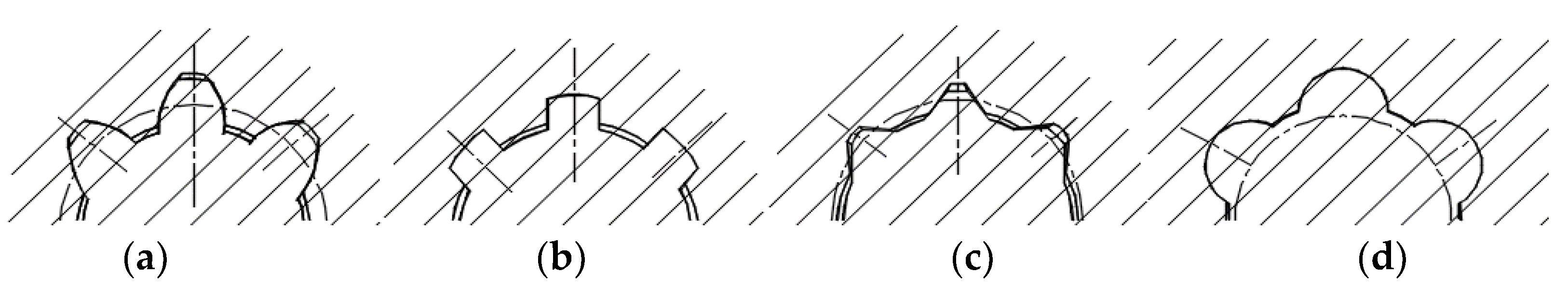
Figure 1. Profile diagram of (a) involute spline, (b) rectangle spline, (c) triangle spline, and (d) circular arc spline.
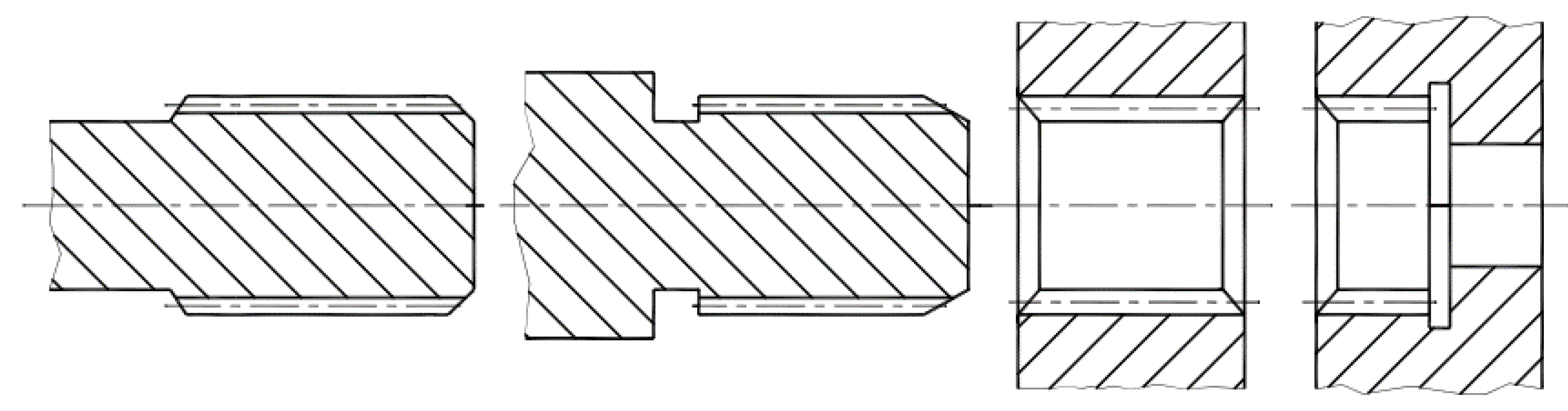
Figure 2. Shapes of spline body: (a) external spline with an open end, (b) external spline with an adjacent shoulder, (c) internal spline with an open end, and (d) internal spline with an adjacent shoulder.
2.2. Spline Classification from Function and Positioning Mode
Splines can be divided into single-stage and multi-stage spline coupling, depending on their functions. The multi-stage spline can reduce torque fluctuation to a certain level and compensate for significant misalignment. Figure 3 shows two representative multi-stage splines (i.e., multi-stage splines with friction plates or a spline sleeve). As shown in Figure 3a, when applying an axial force on the multi-stage spline with friction plates, contact and friction would generate between the internal and external splines, which further transmit torques between the spline shaft and the spline sleeve [5]. As shown in Figure 3b, this type of multi-stage spline inserts a spline sleeve (ring) between the internal and external spline. Such a spline sleeve can be made of various materials, such as metal and nylon [6]. Splines can be divided into fixed and flexible splines according to Dudley’s method for calculating the bearing capacity of involute splines [7]. The fixed spline can be shrink-fitted or loosely fitted, but both ends have piloted rings to keep the spline from rocking. The rocking would result in a small amount of axial movement, which further leads to spline wear. A typical fixed spline is shown in Figure 4 [8].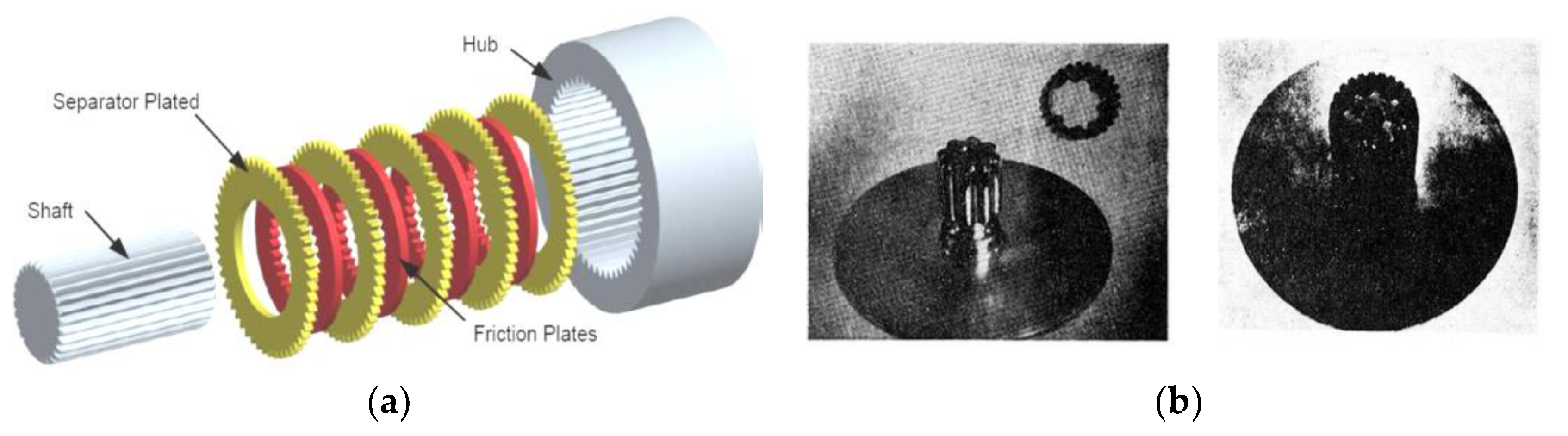
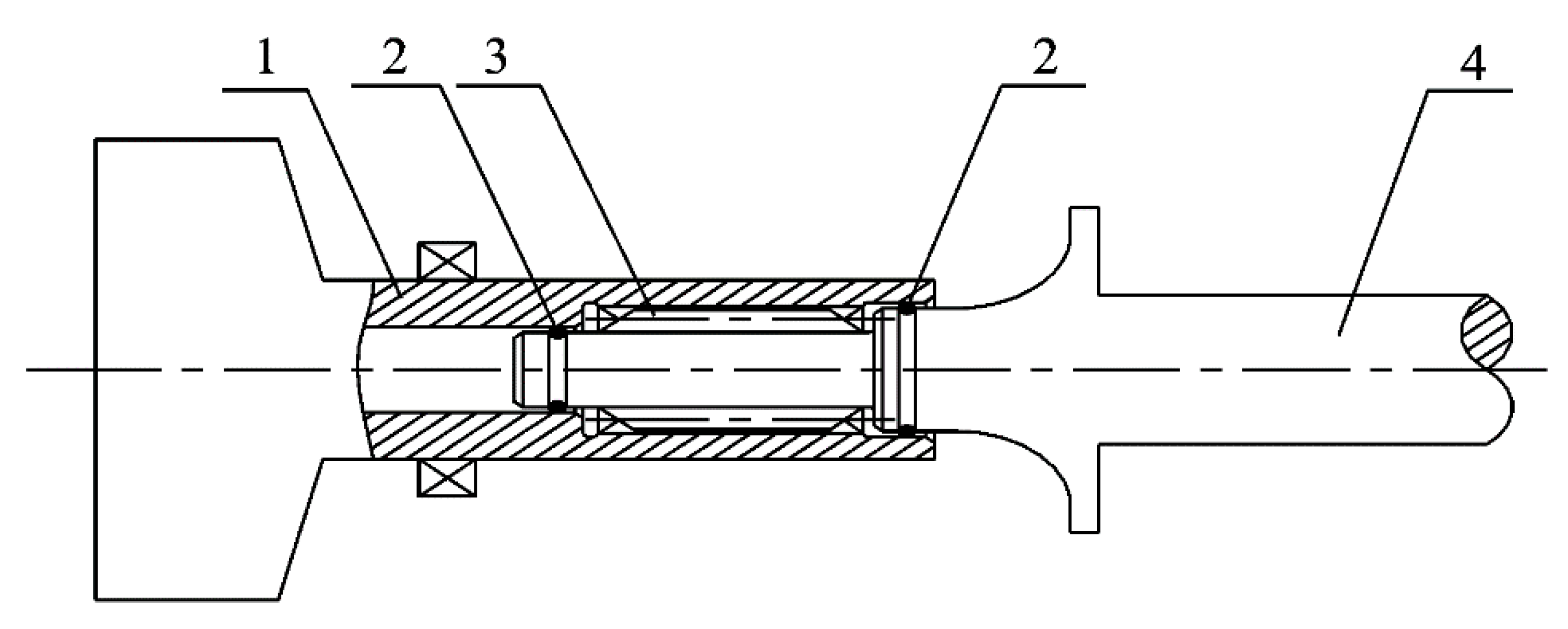
Figure 4. Fixed spline in helicopter tail drive shafts [8]. 1—Output shaft of the main reducer; 2—O-ring; 3—Spline; 4—Tail drive shaft.
2.3. Spline Classification from Modification
Tooth modifications along the axial orientation are often used to improve the contact properties of misaligned splines. These tooth modifications can prevent stress concentration. In general, tooth modifications are performed on the external spline, and the internal spline remains unchanged. Splines with tooth tip centering are usually modified in the top axial direction, while splines with tooth side centering are usually modified in the tooth axial direction and maintain an involute profile. Splines with the second type of tooth modification are called involute crowned splines, abbreviated as crowned splines [10]. As shown in Figure 7 and Figure 8, the crowned tooth surface of crowned splines enhances the friction and wear condition of the tooth surface and reduces noise compared to common splines. It also prevents edge extrusion and stress concentration misuse in a misaligned state. In addition, the internal and external splines are conveniently disassembled and assembled due to the flared shape of the external tooth end.
3. Aviation Spline Wear
Tooth wear is the main problem of aviation splines. Early studies on spline wear were primarily conducted between 1970 and 1985. After receiving thorough treatments, the life of American aviation splines was significantly extended. Spline wear studies have ushered in another upsurge since 2010. China Aviation Engine Group has done a lot of research on improving the anti-wear performance of aviation splines. According to the statistics of AVIC Shenyang Engine Design Institute [33][11], splines and accessories should be inspected gradually every 100 h. Twelve accessories and twelve splines were inspected during one inspection. As shown in Figure 9, five internal splines and eleven external spline shafts of fuel booster pumps were found to have worn severely, and they all needed to be replaced. The troubleshooting experience showed that the main problems of aviation splines are inadequate surface hardness, excessive axial movement value, excessive misalignment, and insufficient lubrication. However, the spline wear problem has not been effectively solved, and the root cause of spline wear and the mechanism of rapid spline wear are still unclear. Thus, it is urgent to carry out in-depth theoretical and experimental research.
Figure 9. Spline wear examples of aero engine accessories [33]. (a) Drive gear shaft internal spline of the fuel booster pump, (b) spline shaft of the fuel booster pump, (c) spline shaft of the fuel booster pump connected to flying attachment end, and (d) spline shaft of the fuel booster pump connected to pump end.
3.1. Influence of Lubrication on Spline Wear
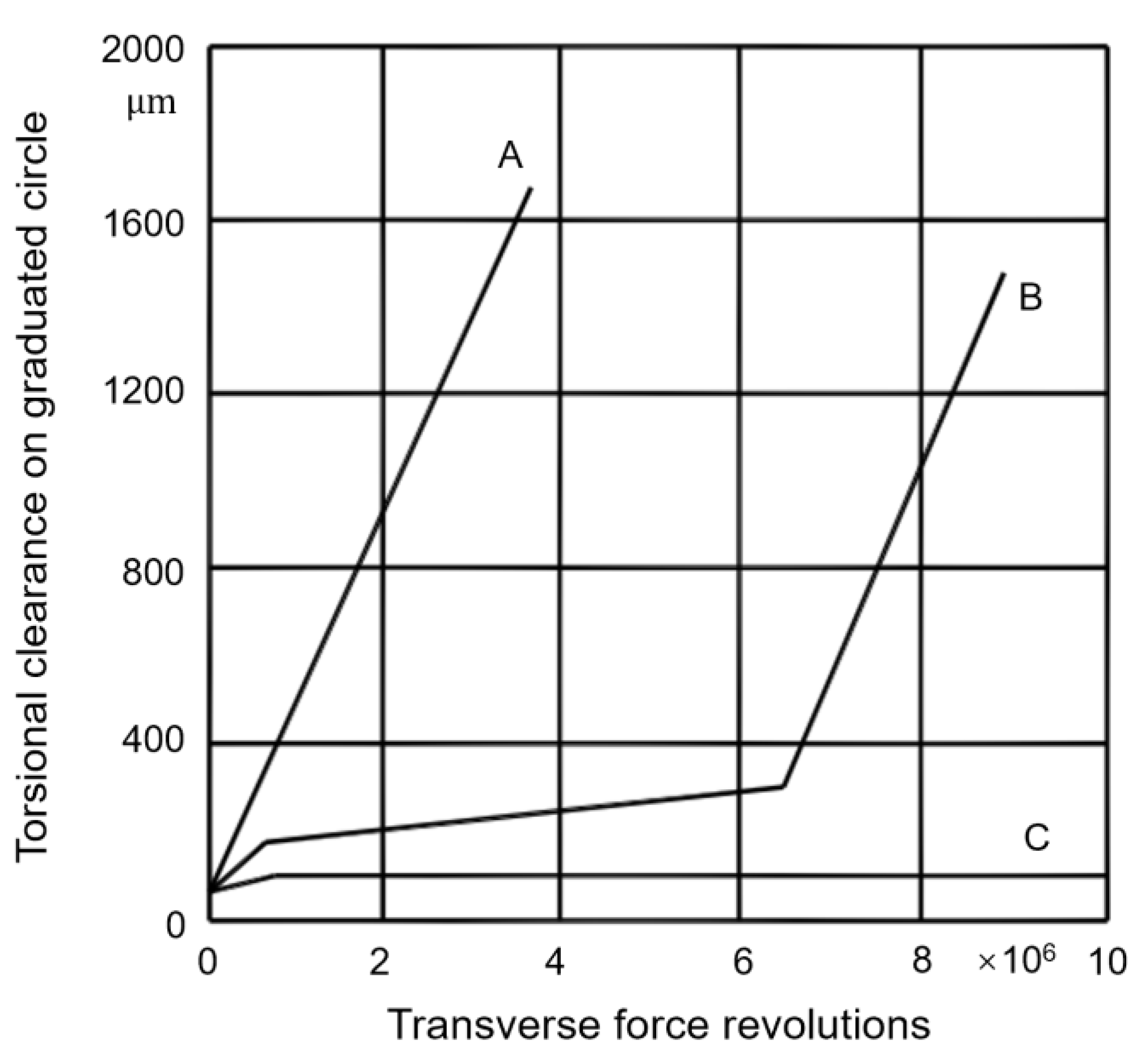
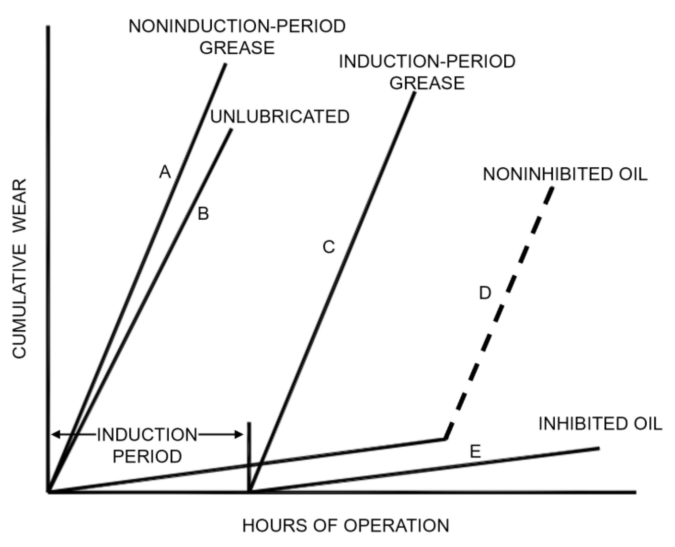
Mating external and internal spline teeth slip with each other when the spline runs at high rotating speeds. The slips may occur in the following three directions, namely axial, radial, and torsional directions. Friction and heating issues are very prominent when considering variables like misalignment and vibration, so splines require reliable lubrication [35][13]. Splines are often lubricated using grease, oil/oil mist, or no lubrication. Grease-lubricated splines are simple to operate, easy to maintain, and highly reliable. They also have a unique property of sealing teeth from the environment. Grease-lubricated splines have drawbacks in that they are greatly affected by working temperature and have poor grease continuity and retention. When the grease is thrown out or completely squeezed out due to centrifugal force, the friction coefficient between the mating spline teeth increases as a result of no lubrication. In addition, the oxide coating cannot be produced because grease prevents air from entering the spline tooth surface at the initial stage. In small misalignment states, the aviation spline generates very little heat, and its temperature rise mainly comes from the heat transfer from the attached shaft. Currently, few lubricating greases can work at temperatures above 121 °C. Grease lubrication is therefore inappropriate for the enclosed area because its heat is difficult to dissipate. Continuous oil/oil mist lubrication makes the heat output from the spline increase rapidly, so splines running at high speed with oil lubrication would still have greater continuous service performance. The disadvantages of oil lubrication include its high cost and the needs of additional pipelines, oil stations, and other auxiliary systems. What is more, the spline wear will be accelerated once impurities enter the working environment through the lubricating oil. The non-lubricated spline is often used in conditions with compact structure, low running speed, light torque, and high working temperature. Additionally, the spline can use intermittent or discontinuous lubrication, or the radial hole can be employed to direct lubricating oil toward the spline engagement point, and the lubrication can be achieved through capillary actions [36][14]. Although the lubrication mode has the above rules to follow, it also needs to be determined according to the actual structure and working environment. Spline wear is a complicated process that can be either mechanical, chemical, or both. Mechanical wear can be significantly alleviated by selecting the correct lubricant. If the lubricant is unable to reduce the creation of wear debris, wear propagation will dominate the wear process. The hardness of oxides is often higher than that of the spline matrix. That is, if wear debris remains in the lubricant, it will instead aggravate spline wear and even lead to connection failure. Essentially, grease lubrication cannot play a positive role if the aim is to improve the service life of splines. According to laboratory tests [37][15], splines need to be cleaned and relubricated at least every 50 h of operation. For aviation splines, the downtime is unbearable, to say nothing of the high maintenance costs. Only oil lubrication can achieve a significant improvement because, in addition to friction characteristics, lubricating oil can wash away the wear debris and further achieve complete lubrication. A summary of the influence of lubrication mode on spline wear is shown in Figure 110 [34][12].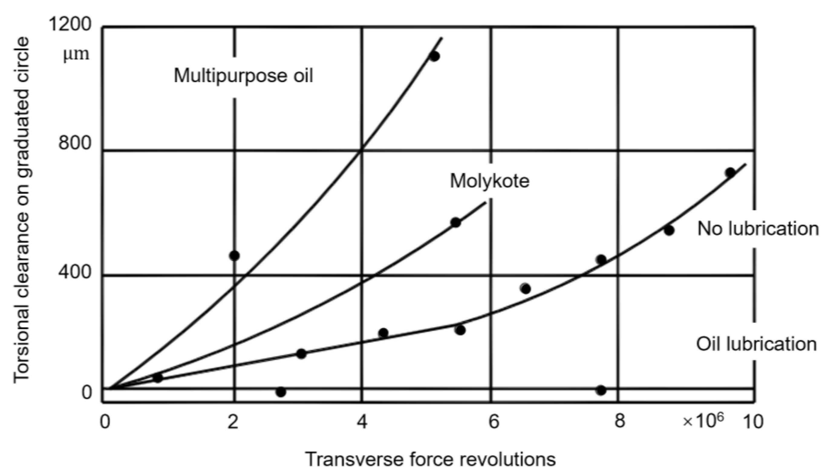
3.2. Effect of Misalignment on Spline Wear
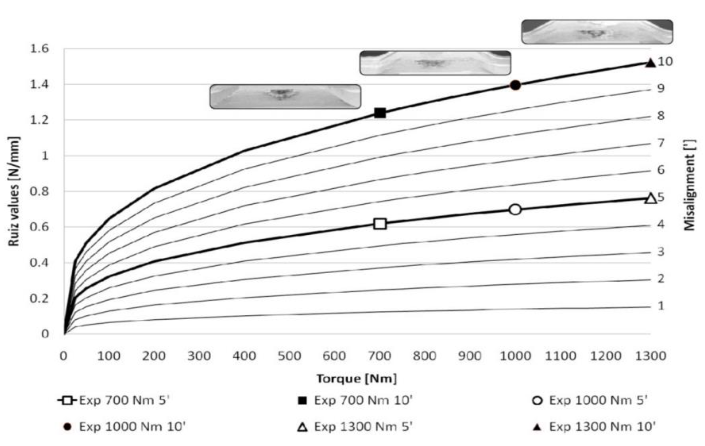
Although the good alignment of connected rotors is required by spline assembly standards, in practice, manufacturing and assembly errors, component tolerances, dirty assembly surfaces, wear, and cold and hot deformations together would lead to large misalignment. Misalignments can cause a number of problems, such as vibrations in the spline rotor [40][18], spline teeth breakage, scratches, cold deformation, wear, and pitting. Misalignment also generates considerable axial force. According to ARINC measurements, the axial force generated by significant misalignment is large enough to disengage the coupling. The axial force generated by a misaligned spline greater than 2 degrees can be as much as 900 N [2]. Curà et al. [41][19] established a theoretical method based on a non-finite element method to determine the exact number of engaging teeth and shared forces in involute spline couplings with parallel offset errors. Elkholy and Alfres [42][20] addressed that misalignment leads to a redistribution of the load on each spline tooth, which increases the maximum contact and bending stresses of the tooth. The uneven load on the tooth also generates tilting and friction moments, which will further transfer to bearings. Test investigations show that misalignment has a significant effect on spline reliability, wear, and life [4]. As shown in Figure 123, misalignment significantly increases spline wear, and a small increase in misalignment results in a sharp increase in wear and a sharp decrease in wear life. The most efficient way to extend wear life and decrease wear on splines, as well as the most efficient way to simplify spline design and lower lubrication and maintenance pressure, is strict control of misalignment. In view of the inevitability and severity of spline misalignment, Ref. [43][21] gives the requirements for misalignment control of couplings in rotating machinery.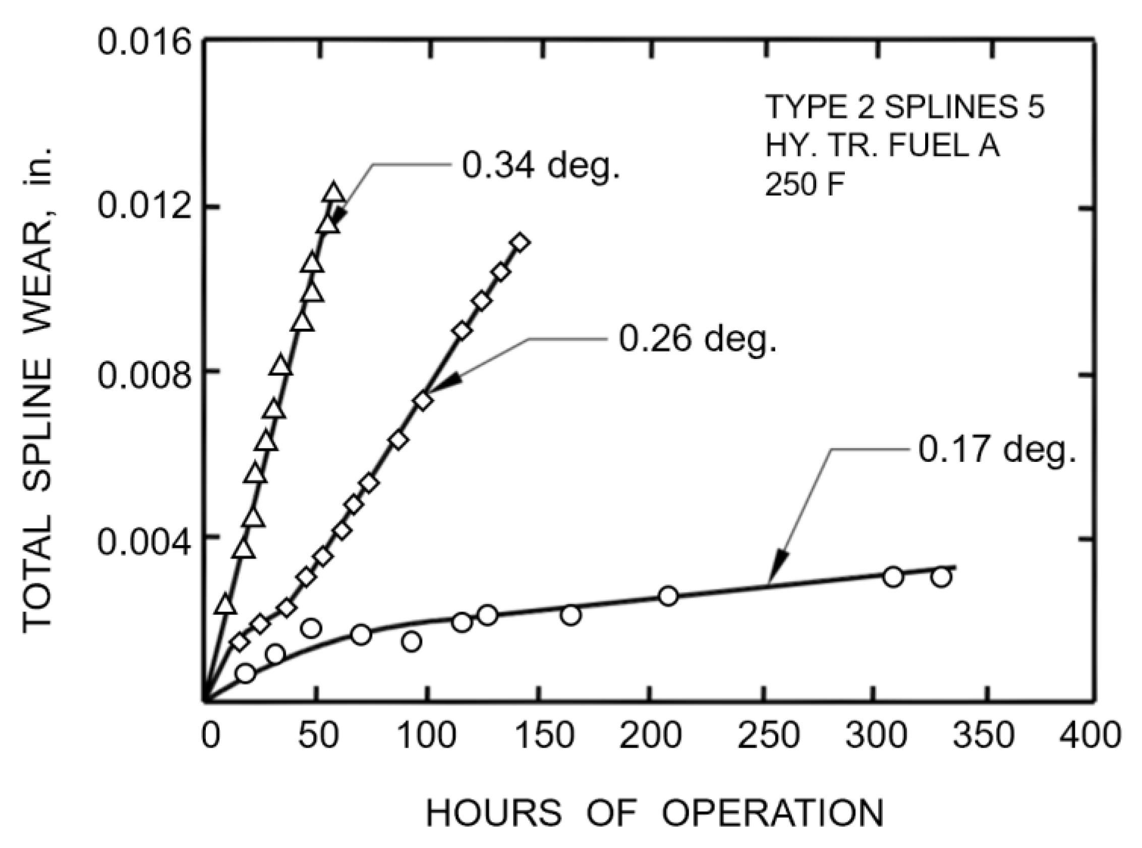
References
- Wang, Y.L.; Zhao, G.; Sun, X.C.; Shengxiang, L.I. Review on Research of Aviation Spline. Aeronaut. Manuf. Technol. 2017, 60, 91–100.
- Coss, R.A.; Gantschnigg, G.K. Aircraft Electric System and System Component Study (F-4 Type Aircraft); Interim Report; ARINC Research Corporation: Annapolis, MD, USA, 1967.
- Endoy, R. Gear Hobbing, Shaping, and Shaving: A Guide to Cycle Time Estimating and Process Planning; Society of Manufacturing Engineers: Dearborn, MI, USA, 1990; pp. 63–74.
- Ku, P.M.; Valtierra, M.L. Spline wear-effects of design and lubrication. J. Eng. Ind. 1975, 97, 1257–1263.
- Chase, K.W.; Sorensen, C.D.; De Caires, B. Variation Analysis of Tooth Engagement and Load Sharing in Involute Splines. Gear Technol. 2010, 7, 54–62.
- Brown, H.W. A Reliable Spline Coupling. J. Eng. Ind. 1979, 101, 421.
- Dudley, D.W. When Splines Need Stress Control. Prod. Eng. 1957, 28, 56–61.
- Kang, L.X.; Cao, Y.H.; Mei, Q. Dynamic Instability of Helicopter Transmission Rotating Shafts with Spline Coupling. J. Beijing Univ. Aeronaut. Astronaut. 2010, 36, 645–649.
- Fu, C.G.; Zheng, D.P.; Ou, Y.X.; Zhou, S.J.; Zhao, X.M. Aeroengine Design Manual (Volume 19); Aviation Industry Press: Beijing, China, 2000; pp. 34–78.
- Zhao, G.; Wang, M.R.; Feng, Z.F.; Wang, Y.Q.; Guo, M.; Su, C.Q. Design method and its misaligned contact characteristic of aviation crowned spline. J. Aerosp. Power 2022, 37, 694–703.
- Chen, C.H. The Common Failures of Aero-engine Mechanical System; Aviation industry Press: Beijing, China, 2013; pp. 72–78.
- Dietz, P.; Schafer, G.; Wesolowski, K. Strength and Abrasion Wear of Involute Splines. Chin. J. Eng. Des. 1996, 1, 31–38+46.
- Liu, W.M.; Xia, Y.Q.; Fu, X.G. Gear Drive Lubricating Materials; Chemical Industry Press: Beijing, China, 2005; pp. 14–73.
- Calistrat, M.M. Gear Coupling Lubrication; American Society of Lubrication Engineers: Chicago, IL, USA, 1974.
- Waterhouse, R.B. Fretting Fatigue; Applied Science Publishers: London, UK, 1981.
- Weatherford, W.D.; Valtierra, J.R.M.L. Mechanisms of Wear in Misaligned Splines. J. Lubr. Technol. 1968, 90, 42–48.
- Mura, A.; Curà, F.; Adamo, F. Evaluation of graphene grease compound as lubricant for spline couplings. Tribol. Int. 2018, 117, 162–167.
- Zhao, G.; Guo, J.N.; Wang, X.F.; Liu, Z.S. Dynamics of Rotor-Gear Coupling-Bearing System with Misalignment. J. Dalian Univ. Technol. 2011, 51, 338–345.
- Curà, F.; Mura, A.; Gravina, M. Load Distribution in Spline Coupling Teeth with Parallel Offset Misalignment. J. Mech. Eng. Sci. 2012, 227, 1–11.
- Elkholy, A.H.; Alfares, M.A. Misalignment Loads in Splined Gear Coupling. Int. J. Comput. Appl. Technol. 2002, 15, 128–137.
- Boyce, M.P. Shaft Alignment in The Gas Turbine Engineering Handbook, 3rd ed.; Gulf Professional Publishing: Boston, MA, USA, 2006; pp. 654–663.
- Leen, S.B.; McColl, I.R.; Ratsimba, C.H.H.; Williams, E.J. Fatigue Life Prediction for A Barrelled Spline Coupling Under Torque Overload. J. Aerosp. Eng. 2003, 217, 123–142.
- Waterhouse, R.B. Fretting Wear, in ASM Handbook, Friction, Lubrication and Wear Technology. Am. Soc. Met. 1992, 18, 242–256.
- Jason, J.M. Numerical Modelling of the Effect of Fretting Wear on Fretting Fatigue. Ph.D. thesis, University of Nottingham, Nottingham, UK, 2009.
- Leen, S.B.; Richardson, I.J.; McColl, I.R.; Williams, E.J.; Hyde, T.R. Macroscopic Fretting Variables in A Splined Coupling Under Combined Torque and Axial Load. J. Strain Anal. Eng. Des. 2001, 36, 481–497.
- Sum, W.S.; Leen, S.B.; Williams, E.J.; Sabesan, R.; McColl, I.R. Efficient Finite Element Modelling for Complex Shaft Couplings Under Non-Symmetric Loading. J. Strain Anal. Eng. Des. 2005, 40, 655–675.
- Liu, H.Y. Influence of Spline Matching Clearance on Spline Coupling Failure. Journal of Changchun University 2008, 18, 41–43.
- Houghton, D.; Wavish, P.M.; Williams, E.J. Multiaxial Fretting Fatigue Testing and Prediction for Splined Couplings. Int. J. Fatigue 2009, 31, 1805–1815.
- Curà, F.; Mura, A. Evaluation of the Fretting Wear Damage on Crowned Splined Couplings. Procedia Struct. Integr. 2016, 5, 1393–1400.
More