Your browser does not fully support modern features. Please upgrade for a smoother experience.
Please note this is a comparison between Version 2 by Jessie Wu and Version 4 by Jessie Wu.
The applications of Simultaneous Localization and Mapping (SLAM) for atechnique has achieved astonishing progress and has generated considerable interest in the autonomous driving with respect to different driving scenarios, vehicle system components and the characteristics of the SLAM approaches are discussed. A real-world road test is presented to demonstrate a multi-sensor-based modernizedcommunity. With its conceptual roots in navigation and mapping, SLAM outperforms some traditional positioning and localization techniques since it can support more reliable and robust localization, planning, and controlling to meet some key criteria for autonomous driving. An overview of the different SLAM implementation approaches and then discuss the applications of SLAM procedure for autonomous driving. The numerical results show that a high-precision 3D point cloud map can be generated by with respect to different driving scenarios, vehicle system components and the characteristics of the SLAM procedure with the integration of Lidar and GNSS/INSapproaches are given.
- Simultaneous Localization and Mapping
- autonomous driving
- localization
- high definition map
1. Introduction
D
Autonomous (also callepd sending on the different characteristics of Simultaneous Localization and Mapping (SLAM) techniques, there could be different applicatilf-driving, driverless, or robotic) vehicle operation is a significant academic as well as an industrial research topic. It is predicted that fully autonomous vehicles will become an important part of total vehicle sales in the next decades. The promotion of autonomous vehicles draws attention to the many advantages, such as service for disabled or elderly persons, reduction in driver stress and costs, reduction in road accidents, elimination of the need for conventional public transit services, etc. [1][2].
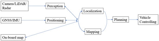
A typical autonomous for auvehicle system contains four key parts: localization, perception, planning, and controlling (Figure 1). Positionomous driving. One classificing is the process of obtaining a (moving or static) object’s coordinates with respect to a given coordinate system. The coordinate system may be a local coordinate system or a geodetic datum such as WGS84. Localization of the applications is whether they are offline is a process of estimating the carrier’s pose (position and attitude) in relation to a reference frame or a map. The perception system monitors the road environment around the host vehicle and identifies interested objects such as pedestrians, other vehicles, traffic lights, signage, etc.
 By determining the coor online. A map satisfyingdinates of objects in the surrounding environment a map can be generated. This process is known as Mapping.
Path pla high-performance requirement is typically generated offline, sucnning is the step that utilizes localization, mapping, and perception information to determine the optimal path in subsequent driving epochs, guiding the automated vehicle from one location to another location. This plan is then converted into action using the controlling system components, e.g., brake control before the detected traffic lights, etc.
All these as the High Definition (HD)parts are closely related. The location information for both vehicle and road entities can be obtained by combining the position, perception, and map [1]information. FIn cor this kind of 3D point cloud map, an ontrast, localization and mapping can be used to support better perception. Accurate localization and perception information is essential for correct planning and controlling.
To achieve ffulline map generation process ensures the accuracy and reliability of the map. Such maps can be pre-generated to support the real-time operatiy automated driving, there are some key requirements that need to be considered for the localization and perception steps. The first is accuracy. For autonomous driving, the information about where the road is and where the vehicle is within the lane supports the planning and controlling steps. To realize these, and to ensure vehicle safety, there is a stringent requirement for position estimation at the lane level, or even the “where-in-lane” level (i.e., the sub-lane level). Recognition range is important because the planning and controlling steps need enough processing time for the vehicle to react [3]. Robustns of autonomous vehicles.
By determining the coor online. A map satisfyingdinates of objects in the surrounding environment a map can be generated. This process is known as Mapping.
Path pla high-performance requirement is typically generated offline, sucnning is the step that utilizes localization, mapping, and perception information to determine the optimal path in subsequent driving epochs, guiding the automated vehicle from one location to another location. This plan is then converted into action using the controlling system components, e.g., brake control before the detected traffic lights, etc.
All these as the High Definition (HD)parts are closely related. The location information for both vehicle and road entities can be obtained by combining the position, perception, and map [1]information. FIn cor this kind of 3D point cloud map, an ontrast, localization and mapping can be used to support better perception. Accurate localization and perception information is essential for correct planning and controlling.
To achieve ffulline map generation process ensures the accuracy and reliability of the map. Such maps can be pre-generated to support the real-time operatiy automated driving, there are some key requirements that need to be considered for the localization and perception steps. The first is accuracy. For autonomous driving, the information about where the road is and where the vehicle is within the lane supports the planning and controlling steps. To realize these, and to ensure vehicle safety, there is a stringent requirement for position estimation at the lane level, or even the “where-in-lane” level (i.e., the sub-lane level). Recognition range is important because the planning and controlling steps need enough processing time for the vehicle to react [3]. Robustns of autonomous vehicles.
Figure 1. Functional components of an autonomous driving system.
2. High Definition Map Generation and Updating
Aess means the localization and perception should be robust to any changes while driving, such as driving statecenarios (urban, highway, tunnel, rural, etc.), lighting conditions, weather, etc.
Traditional earlier, SLAM can be used to generate digital maps used for autonomous driving, such as the HD mapvehicle localization and perception techniques cannot meet all of the aforementioned requirements. For instance, GNSS error occurs as the signals may be distorted, or even blocked, by trees, urban canyons, tunnels, etc. Often an inertial navigation system (INS) is used to support navigation during GNSS signal outages, to continue providing position, velocity, and altitude information. However, inertial measurement bias needs frequently estimated corrections or calibration, which is best achieved using GNSS measurements. Nevertheless, an integrated GNSS/INS system is still not sufficient since highly automated driving requires not only positioning information of the host [1].vehicle, Dbue to the stringent requirementst also the spatial characteristics of the objects in the surrounding environment. Hence perceptive sensors, such as Lidar and Cameras, are often used for both localization and perception. Lidar can acquire a 3D point cloud directly and map the environment, with the aid of GNSS and INS, to an accuracy that can reach the centimeter level in urban road driving conditions [4]. However, the high quality sensors are used.cost has limited the commercial adoption of Lidar systems in vehicles. Furthermore, its accuracy is influenced by weather (such as rain) and lighting conditions. Compared to Lidar is one of, Camera systems have lower accuracy but are also affected by numerous error sources [5][6]. Nevertheless, they core sensors for automated cars asare much cheaper, smaller in size, require less maintenance, and use less energy. Vision-based systems can provide abundant environment information, similar to what human eyes can perceive, and the data can be fused with other sensors to determine the location of detected features.
A map wit can generate high-density 3D point clouds. High-end GNSS and INS technology are also used toh rich road environment information is essential for the aforementioned sensors to achieve accurate and robust localization and perception. Pre-stored road information makes autonomous driving robust to the changing environment and road dynamics. The recognition range requirement can be satisfied since an onboard map can provide accurate position infotimely information on the road network. Map-based localization and navigation have been studied using different types of map information. Cameras can Google Map is one example as it provides worldwide map information that iincluding images, topographic details, and satellite images [7], and it is available vimilar to the information detea mobile phone and vehicle apps. However, the use of maps will be limited by the accuracy of the maps, and in some selected areas the map’s resolution may be inadequate. In [8], the authors ctonsidered by human eyes. The low-accuracy maps for navigation by combining data from other sensors. They detected moving objects using Lidar data and utilized a GNSS/INS system with a coarse open-source GIS map. Their results show their fusion oftechnique can successfully detect and track moving objects. A precise curb-map-based localization method that uses a 3D-Lidar sensor daand a high-precision map is proposed in [9]. However, this method will fa andil when curb information is lacking, or obstructed.
Recently, so-canalysis oflled “high-definition” (HD) maps have received considerable interest in the context of autonomous driving since they contain very accurate, and large volumes of, road network information [10]. According to some major players in the commercial HD map market, 10–20 cm accuracy has been achieved [11][12], and it is predicted that in the next generateion of HD maps needs con, a few centimeters of accuracy will be reached. Such maps contain considerable computational power, which is not feasible in current onboard vehicle systemsinformation on road features, not only the static road entities and road geometry (curvature, grades, etc.), but also traffic management information such as traffic signs, traffic lights, speed limits, road markings, and so on. The autonomous car can use the HD map to precisely locate the host-car within the road lane and to estimate the relative location of the car with respect to road objects by matching the landmarks which are recognized by onboard sensors with pre-stored information within the HD map.
Therefore, themaps, especially HD map is built-up offline, using tes, play several roles in support of autonomous driving and may be able to meet the stringent requirements of accuracy, precision, recognition ranging, robustness, and information richness. However, the application of the “map” for autonomous driving is also facilitated by techniques such as optimization-based SLAM. The ofSimultaneous Localization and Mapping (SLAM). SLAM is a process by which a moving platform builds a map of the environment and uses that map to deduce its location at the same time. SLAM, which is widely used in the robotic field, has been demonstrated [13][14] as being applicable for autonomous vehicline operations as it can support not only accurate map creatgeneration but also online localization within a previously generated map.
With appron can be performed bypriate sensor information (perception data, absolute and dead reckoning position information), a high-density and accurate map can be generated offline by SLAM. When driving the road network several times to collect, the self-driving car can locate itself within the pre-stored map by matching the sensor data to the map. SLAM can also be used to address the problem of DATMO (detection and tracking of moving objects) [15] which is importanformation, and then all the collected perceptive sensor infort for detecting pedestrians or other moving objects. As the static parts of the environment are localized and mapped by SLAM, the dynamic components can concurrently be detected and tracked relative to the static objects or features. However, SLAM also has some challenging issues when applied to autonomous driving applications. For instance, “loop closure” can be used to reduce the accumulated bias within SLAM estimation and position informatioin indoor or urban scenarios, but it is not normally applicable to highway scenarios.
2. Key SLAM Techniques
Since is pts initial introduction in 1986 [16], a variety ocessed tof SLAM techniques have been developed. SLAM has its conceptual roots in geodesy and geospatial mapping [17]. In general, ther to improve the accuracy of the fe are two types of approaches to SLAM estimation: filter-based and optimization-based. Both approaches estimate the vehicle pose states and map states at the same time. The vehicle pose includes 3D or 2D vehicle position, but sometimes also velocity, orientation or attitude, depending on the sensor(s) used and on the application(s).2.1. Online and Offline SLAM
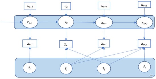
Figure 2 and Figure 3 illustrate two general SLAM implementations: online SLAM al map. Annd offline SLAM (sometimes referred to as full SLAM). According to [18], full SLAM sexample of a HD map is shown ineks to calculate variables over the entire path along with the map, instead of just the current pose, while the online SLAM problem is solved by removing past poses from the full SLAM problem.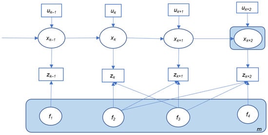
2. Description of online SLAM.
T
Here, xk represents the vehicle pose (position, attitude, velocity, etc.) at time k. m is the map that consists of stored landmarks (f1–f4) with their position states. uk is the controad environmel inputs that represent the vehicle motion information between time epochs k − 1 and k, such as acceleration, and road rules mturn angle, etc., which can be acquired from vehicle motion sensors such as wheel encoders or an inertial sensor. At some epoch k, the onboayrd sensors change, for instance, the speed l(such as Camera, Lidar, and Radar) will perceive the environment and detect one or more landmarks. The relative observations between the vehicle and all the observed landmarks are denoted as zk. With this informit may be ation, the variables (including the vehicle pose and the map states) can be estimated.
The redctangle with blucede background in Figure 2 andu Figure 3 represents the state variables to road work, rohat are estimated in these two implementations. In most cases, for online SLAM, only the current vehicle pose xk+2 is estimated infrastruwhile the map is generated and updated with the most recent measurements (uk+2 and zk+2), whereas in the case of the offline SLAM implementure may be changed due to buildingation, the whole trajectory of the vehicle is updated together with the whole map. All the available control and observation measurements will be utilized together for the offline SLAM implementation.
However, with the development of SLAM algorithms and increased computational capabilities, and so on the full SLAM solution may be obtained in real-time with an efficient SLAM algorithm, which can also be treated as an online problem. Therefore the HD map needs frequent update, implementing a SLAM method online or offline may be dependent on whether the measurement inputs (control and observation) it requires are from current/history or from future epochs, and on its processing time (real-time or not).
Description of offline SLAM.
2.2. Filter-Based SLAM
Filter-bas.ed Such updates can utilize the oLAM recursively solves the SLAM problem in two steps. Firstly, the vehicle and map states are predicted with processing models and control inputs. In the next step, a correction of the predicted state is carried out using the current sensor observations. Therefore, the filter-based SLAM is suitable for online SLAM. Extended Kata collectelman Filter-based SLAM (EKF-SLAM) represents a standard solution for the SLAM problem. It is derived from any autonomous car. For example, the daBayesian filtering in which all variables are treated as Gaussian random variables. It consists of two steps: time update (prediction) and measurement update (filtering). At each time epoch the measurement and motion models are linearized (using the current state with the first-order Taylor expansion). However, since the linearization is not made around the true value of the state vector, but around the estimated value [19], the lineariza is transmittion error will accumulate and could cause a divergence of the estimation. Therefore, inconsistencies can occur. Anothed to central (cloud) computers where the updatr issue related to EKF-SLAM is the continuous expansion of map size which makes the quadratic calculation process of large-scale SLAM impractical. For autonomous driving, the complex road environment and long driving period will introduce a large number of features, which makes real-time computations are performed. Other n not feasible. A large number of algorithms have been developed in order to improve computational efficiency. For example, the Compressed Extended Kalman Filter (CEKF) [20] algorithm can significantly rs can receive such cloud-educe computations by focusing on local areas and then extending the filtered information to the global map. Algorithms with sub-maps have also been used to address the computation issues [21][22][23][24]. A new blased updates and make a timnk map is used to replace the old map when the old one reaches a predefined map size. A higher-level map is maintained to track the link between each sub-map. There are some other fily adjustment to driving plans. Jo et al.ter-based SLAM approaches, such as some variants of the Kalman Filter. One of them, the Information Filter (IF), is propagated with the inverse form of the state error covariance matrix, which makes this method more stable [325]. prThis method is more popular in multi-vehicle SLAM than in single-vehicle systems. Anopther class osed af filter-based SLAM change update (SLAMCU) algorithm, utilizing a techniques is the Particle Filter (PF) which has become popular in recent years. PF executes Sequential Monte-Carlo (SMC) estimation by a set of random point clusters (or particles) representing the Bayesian aposteriori. The Rao–Blackwellized PF approarticle Filter was proposed in [26]. Fast-SLAM is ach for online vehicle popular implementation that treats the robot position and (new) map state estimationdistribution as a set of Rao–Blackwellized particles, and uses an EKF to maintain local maps. In the work ofis way, the computational complexity of SLAM is greatly reduced. Real-time application is possible with Fast-SLAM [427], ma new feature layer of HD mapking online SLAM possible for autonomous driving. Another advantage over EKF is that the particle filters can be genecope with non-linear motion models [28]. However, atccording to [29][30], Fast-SLAM suffers from d using Graph egeneration since it cannot forget the past. If marginalizing the map and when resampling is performed, statistical accuracy is lost.2.3. Optimization-Based SLAM
Full SLAM whestimaten a s all the vehicle is temporarily stopped or in a parking lot. The new feature layer from one vehicle can then be uploadpose and map states using the entire sensor data, and it is mostly optimization based. Similar to filter-based SLAM, the optimization-based SLAM system consists of two main parts: the frontend and the backend. In the frontend step, the SLAM system extracts the constraints of the problem with the sensor data, for example, by performing feature detection and matching, motion estimation, loop closure detection, etc. Nonlinear optimization is then applied to acquire the map cloud andximum likelihood estimation at the backend. Graph SLAM is ontegrated with that from other vehicles into a newe of the main classes of full SLAM which uses a graphical structure to represent the Bayesian SLAM. All the platform poses along the whole trajectory and all the detected feature layer in the map cloud, thus enabling more precise and robust vehicle locals are treated as nodes. Spatial constraints between poses are encoded in the edges between the nodes. These constraints result from observations, odometry measurements, and from loop closure constraints. After the graph construction, graph optimization. In the work of Zhang et al is applied in order to optimize the graph model of the whole trajectory and map. [5],To solve rtheal-time semantic segmentation and Visual full optimization and to calculate the Gaussian approximation of the aposteriori, a number of methods can be used, such as Gauss–Newton or Levenberg–Marquardt [31]. For graph-based SLAM, were combined to the size of its covariance matrix and update time are constant after generate semantic point cloud data oing the graph, therefore graph SLAM has become popular for building large-scale maps. Reducing the computational complexity of the optimization step has become one of the road environment, which was then matched with a pre-constructed HD map to confirm map elements thatmain research topics for practical implementations of the high-dimensional SLAM problem. The key to solving the optimization step efficiently is the sparsity of the normal matrix. The fact that each measurement is only associated with a very limited number of variables makes the matrix very sparse. With Cholesky factorization and QR factorization methods, the information matrix and measurement Jacobian matrix can be factorized efficiently, and hence the computational cost can be significantly reduced. Several algorithms have not changed,been proposed, such as TORO and g2o. The sub-map method is also a popular strategy for solving large-scale problems [32][33][34][35][36]. The sub-maps cand generate new elements when appearing, thus facilitati be optimized independently and are related to a local coordinate frame. The sub-map coordinates can be treated as pose nodes, linked with motion constraints or loop closure constraints. Thus, a global pose graph is generated. In this way the computational complexity and update time will be improved. Smoothing and Mapping c(SAM), anotherowdsource updates of HD maps optimization-based SLAM algorithm, is a type of nonlinear least squares problem. Such a least squares problem can be solved incrementally by Incremental Smoothing and Mapping (iSAM) [37] and iSAM2 [38].3. Small Local Map Generation
Online SLAM can be obtalso be used for small local arined with incremental SAMs as they avoid unnecessary calculations with the entire covariance matrix. iSAM2 is more efficient as it uses a Bayes tree to obtain incremental variable re-ordering and fluid re-linearization.
SLAM++ is another incrementas. One example is within parking areas. The driving speed in a parking l solution for nonlinear least squares optimization-based SLAM which is very efficient. Moreover, for online SLAM implementations, fast state covariance recovery is very important for data association, obtaining reduced state representations, active decision-making, and next best-view [39][40]. SLAM++ has an advantage as it allows for increment is low, therefoal covariance calculation which is faster than other implementations [40].
Table 1 is a summarey of the visioncharacteristics of some typical SLAM technique will be more s. Note that Graph SLAM utilizes all available observations and control information and can achieve very accurate and robust than in other high-speed driving scenarios. The parking area cestimation results. It is suitable for offline applications and its performance relies on a good initial state guess. Filter-based SLAM is more suitable for small-scale environments when used for online estimation, but for the complex environment, a real-time computation may be difficult with the traditional EKF-SLAM. Other variants or fastSLAM should be unknown (public parking lot or garagconsidered. The incremental optimization method can do incremental updating, so as to provide an optimal estimation of a large-scale map with very high efficiency and in real-time.
Table 1. Characteristics of some typical SLAM techniques.
| SLAM | Type | Advantages | Disadvantages | Typical Studies |
|---|---|---|---|---|
| EKF SLAM | Bayesian filter |
|
|
[29][41][42] |
| IF SLAM | Bayesian filter |
|
|
[25][43] |
| CEKF SLAM | Bayesian filter |
|
|
[20][44] |
| Fast SLAM | Particle filter |
|
|
[26][28][30][45] |
| Graph SLAM | Batch Least Squares optimization |
|
|
[46][47][48][49][50][51] |
| iSAM2 | Incremental optimization |
|
|
[37][38] |
| SLAM++ | Incremental optimization |
|
|
[39][40] |
2.4. Sensors and Fusion Method for SLAM
Ne),w SLAM or known (home zone)–both cases can benefit from SLAM. Since SLAM can be used withoumethods have appeared thanks to advances in sensor and computing technology. These methods are also optimization-based or filtered-based at the backend estimation step while the frontend step is highly dependent on the application of different sensor modalities. Two of the major sensors used for SLAM are Lidar and Camera. The Lidar method has become popular due to its simplicity and accuracy compared to other sensors [52]. The core of Lidar-based localization GNSS signals, it is suitable for vehicles in indand mapping is scan-matching, which recovers the relative position and orientation of two scans or point clouds. Popular approaches for scan matching include the Iterative Closet Point (ICP) algorithm and its variants [53][54][55], and the normal distributior n transform (NDT) [56]. These methods ar undee highly dependent on good initial guess, and are impacted by local minimums [57][58]. Some other matchinground parking methods include probabilistic methods such as correlative scan matching (CSM) [59], featureas-based methods [57][60], and using just the perceptivothers. Many of the scan-matching methods focus on initial free of or robust to, initialization error, but they still face the computation efficiency challenge. Some range sensors and odometry measurements (that can be used for SLAM estimation are Radar and Sonar/ultrasonic sensors. Radar works in a similar manner to Lidar, but the system emits radio waves instead of light to measure the distance to objects. Furthermore, since Radar can observe the relative velocity, turn angle) or IMU between the sensor and the object using the measuremend Doppler shift [61], it is. For unknown public suitable for distinguishing between stationary and moving objects, and can be used to discard moving objects during the map-building process p[62]. Some researkch on using areRadar for SLAM can be found in [42][62][63][64][65][66]. When compared to Lidar, lower price, lower power cons, the position of the car and the obstacumption, and less sensitivity to atmospheric conditions make it well suited for outdoor applications. However, Radar has lower measurement resolution, and its detections are more sparse than Lidar. Thus, it is harder to match Radar data and deal with the data association problem, which results in its 3D mapping being less accurate. Sonar/ultrasonic ses, such as pillars, sidewallsnsors also measure the time-of-flight (TOF) to determine the distance to objects, by sending and receiving sound waves. Sonar-based SLAM was initially used for underwater [67][68], and indoor [69] applications. It has become popular due to itc.,s low cost and low power consumption. It is not affected by visibility restrictions and can be estused with multiple surface types [70]. However, similated at the same time, guiding the parking syr to Radar, it obtains sparse information and suffers from inaccurate feature extraction and long processing time. Thus, it is of limited use for high-speed vehicle applications. Moreover, Sonar/ ultrasonic sensors have limited sensing range and may be affected by environmental noise and other platforms using ultrasound with the same frequency [71]. Camera is anotem. For home zonher popular sensor for SLAM. Different techniques have been developed, such as monocular [72][73], stereo p[74][75][76][77], and multi-camerka [78][79][80][81]. These techniques can be used in a wide rang, the pre-gene of environments, both indoor and outdoor. The single-camera system is easy to deploy, however, it suffers from scale uncertainty [82]. Stereo-camera systed map and a frequent parking trajectorms can overcome the scale factor problem and can retrieve 3D structural information by comparing the same scene from two different perspectives [61]. Multi-camera systems have gained can be stored wincreasing interest, particularly as they achieve a large field of view [78] or are even capable of panoramic visiton [81]. Thins the automated vehiclesystem is more robust in complicated environments, while single sensor system. Eac may be very vulnerable to environmental interference [81]. However, the time the car retintegration of Cameras requires additional software and hardware, and requires more calibration and synchronization effort [71][83]. Another special Camera, the RGB-D Camera, has been studied by the SLAM and computern vision communities [84][85][86][87][88][89][90][91] since it can directly obtain depth infome, re-localization using the storrmation. However, this system is mainly applicable in indoor environments because it uses infrared spectrum light and is therefore sensitive to external illumination [70]. Thed map can be carried out by matching deteVisual SLAM can also be classified as feature-based or direct SLAM depending on how the measurements are used. The feature-based SLAM repeatedly detects features in images and utilizes descriptive features for tracking and depth estimation [92]. Some fundamental frameworks for this feature-based system include MonoSLAM [72][93], PTAM [94], ORB-SLAM [95], and ORB-SLAM2 [96]. Instead fof using any features with the map detectors and descriptors, the direct SLAM method uses the whole image. Examples of direct SLAM include DTAM [97], LSD-SLAM [73], and SVO [98]. ThA dense or semi-dense frequent trajectory could be useenvironment model can be acquired by these methods, which makes them more computationally demanding than feature-based methods. Engel et al. [74] extended the LSD-SLAM for the prom a monocular to a stereo model while Caruso et al. [99] extended the LSD-SLAM to an omnidirectional model. A detailed review of Visual SLAM canning be found in [5] and [70][92][100][101]. Each ontrolling stepf these perceptive sensors has its advantages and limitations.An Lidar approaches that utilizes multi-level surface (MLS) maps to locate the vehicle, and to calculate and plan the can provide precise and long-range observations, but with limitations such as being sensitive to atmospheric conditions, being expensive, and currently rather bulky. Radar systems are relatively low cost, but are more suitable for object detection than for 3D map building. Sonar/ultrasonic sensors are not suitable for high-speed platform applications. Cameras are low-cost, even when multiple Cameras are used. Cameras can also provide rich visual information. However, they are sensitive to environment texture and light, and in general, have high computational demands. Therefore, a popular strategy is to combine a variety of sensors, making the SLAM system more robust.
There are several strategies to intehicle grate data from different sensors for SLAM. One is fusing independently processed sensor results to then obtain the final solution. In [102], a mapping method thath within indoor parking areas merged two grid maps, which were generated individually from laser and stereo camera measurements, into a single grid map was proposed in. In this method, the measurements of the different sensors need to be mapped to a joint reference system. In [6103]., a In this rearch, graphmulti-sensor SLAM system that combined the 3-DoF pose estimation from laser readings, the 6-DoF pose estimation from a monocular visual system, and the inertial-based SLAM was used for mapping navigation estimation results to generate the final 6-DoF position using an EKF processing scheme was proposed. For this type of strategy, the sensors can provide redundancy and the system will be robust to possible single-sensor failure. A decision-making step may be needed to identify whether the data from each sensor is reliable, and the MLS map is then used to plan a global path from the staro decide whether to adopt the estimation from that sensor modality or to ignore it. Another fusion strategy is using an assistant sensor to improve the performance of other sensor-based SLAM algorithms. The main sensor could be Lidar or Camera, while the assistant sensor could be any other type of sensor. In this strategy, the assistant sensor is used to overcome the limitations of the main sensor. The work in [104] incorporated visual to the destininformation to provide a good initial guess on the rigid body transformation, and to robustlyhen used this initial transformation to seed the ICP framework. Huang et al. [105] extracted the depth of lpocalize the vehicle with laser range measuremenint-based and line-based landmarks from the Lidar data. The proposed system used this depth information to guide camera tracking and also to support the subsequent point-line bundle adjustment to further improve the estimation accuracy.
The above two strategies can be combined. In the work of [7106], the fusing consists of two models, one dea grid map and an Extended Kalman Filter (EKF)ls with feature fusion that utilizes line feature information from an image to remove any “pseudo-segments”, which result from dynamic objects, in the laser segments. Another is a modified EKF SLAM algorithm were used with W-band radar for autframework that incorporates the state estimates obtained from the individual monocular and laser SLAM in order to reduce the pose estimation covariance and improve localization accuracy. This modified SLAM framework can run even when one sensor fails since the sensor SLAM processes are parallel to each other.
Sonme examples omous baf more tight fusion can also be found in the literature. The work of [107] ck-ombin parking. In this research, an efficieed both the laser point cloud data and image feature point data as constraints and conducted a graph optimization with both of these constraints using a specific cost function. Furthermore, an image feature-based loop closure was added to this system to remove accumulation errors.
Inert EKF SLAM algorithm was proposed to enableial SLAM incorporates an inertial measurement unit (IMU) as an assistant sensor. The IMU can be fused with the Camera or Lidar to support pose (position, velocity, attitude) estimation. With an IMU, the attitudes, especially the heading, are observable [108]. The integreal-time processing. Iation of IMU measurements can also improve the motion tracking performance during the gaps of observations. For instance, for a Visual SLAM, illumination change, texture-less area, or motion blur will cause losses of visual tracks [8108]. For a Lidar system, the authors propraw Lidar scan data may suffer from skewing caused by high-acceleration motion, such as moving fast or shaking suddenly, resulting in sensing error that is difficult to account for [109]. The work of [110] used an IMU sensor to dearound-view monitor (AVM)/l with fast velocity changes and to initialize motion estimates for scan-matching Lidar odometry to support their LOAM system. The high-frequency IMU data between two Lidar sensor cans can be used to de-skew Lidar point clouds and improve their accuracy [109].
The fusion of inertial sensors can be as a simetple assistant [111][112] or more tightly codupled [108][113][114][115]. For to recognize the parking lane and to provide rapid loop closinghe simple assistant case, the IMU is mainly used to provide orientation information, such as to support the system initialization. The IMU is used as prior for the whole system, and the IMU measurements are not used for further optimization. For the tightly coupled case, IMU data is fused with Camera/Lidar states to build up measurement models, and then perform state estimation and feedback to the inertial navigation system to improve navigation performance [116]. Therefore above studiesthe former method is more efficient than the latter, however, it is less accurate [117]. For thave demonstrated thae tightly coupled case, a Kalman filter could be used to correct the IMU states, even during GNSS outages [118].
2.5. Deep Learning-Based SLAM
Most both filterf the aforementioned SLAM methods are geometric model-based SLAM and optimization-based SLAM can be used to support efficient and accurate vehicle parking assistance (local area mapping and l, which build up models of platform motion and the environment based on geometry. These methods have achieved great success in the past decade. However, they still face many challenging issues. For instance, Visual SLAM (VSLAM) is limited under extreme lighting conditions. For large-scale applications, the model-based methods need to deal with large amounts of information, such as features and dynamic obstacles. Recently, deep learning techniques, such as data-driven approaches developed in the computer vision field, have attracted more attention. Many researchers have attempted to apply deep learning methods to SLAM problems. Most of the calization), even without GNSS. Iurrent research activities focus on utilizing learning-based methods for VSLAM problems since deep learning techniques have made breakthroughs in the work of Qin et al.areas of image classification, recognition, object detection, and image segmentation [9119]. For instance, pose graph optimizdeep learning has been successfully applied to the visual odometry (VO) problem, which is an important element of VSLAM. Optical flow estimation is performed so as tutilized in some learned VO models as inputs [120][121][122][123][124]. The application achieve an optimized trof learning approaches can be applied in an end-to-end manner without adopting any module in the conventional VO pipeline [125][126]. Wajng ectory at al. [125] introd a global map of a parking lot, with semantic features suchuced an end-to-end VO algorithm with deep Recurrent Convolutional Neural Networks (RCNNs) by combining CNNs with the RNNs. With this algorithm, the pose of the camera is directly estimated from raw RGB images, and neither prior knowledge nor parameters are needed to recover the absolute scale [125]. Li et al. [127] proposed an guide signs, parking lines, and speed bumps. These kiUnsupervised Deep Learning based VO system (UnDeepVO) which is trained with stereo image pairs and then performs both pose estimation and dense depth map estimation with monocular images. Unlike the one proposed by Wang et al. [125], ground truth is of features are mornot needed for UnDeepVO since it operates in an unsupervised manner. The (long-term) stable and robust thaearning-based methods can be combined with the VSLAM system to replace or add on an individual or some modules of traditional SLAM, such as image depth estimation [128][129][130], pose estimation [131][132][133], and loop closure [134][135][136][137], etc., to improve the traditional gmeometricalthod. Li et al. f[138] proposed atures, especially in underground parking environments. An EKF was then used to co fully unsupervised deep learning-based VSLAM that contains several components, including Mapping-net, Tracking-net, Loop-net, and a graph optimization unit. This DeepSLAM method can achieve accurate pose estimation and is robust in some challenging scenarios, combining the important geometric models and constraints into the network architecture and the loss function. Sematic plete the localization system erception of the environment and semantic segmentation are current research topics in the computer vision field. They can provide a high-level understanding of the environment and are extremely important for autonomous driving.4. Localization within the Existing Map
Iapplications. The rapid development of deep learning can assist in the introduction of semantic map-binformation into VSLAM [139] for semantic sedgmentation [140][141][142], localization, a matchnd mapping [143][144][145][146][147], and dynamic objethct removal [148][149][150][151]. Some d is used etailed reviews of deep learning-based VSLAM can be found in [92][139][152][153][154]. Fusion with an inertial senso match “live” data with map informr can also benefit from deep learning techniques, especially the RNN, which has an advantage in integrating temporal information and helping to establish consistency between nearby frames [139]. The integration, of using methovisual and inertial data with RNN or Long Short-Term Memory (LSTM), a variant of RNN that allows RNN to learn long-term trends [155], hasu been proven to be more effective and ch asonvenient than traditional fusion I[156][157][158]. According to Clark et al. [157], therative Closest Point (ICP), Normal Distribution Transform (NDT), and others data-driven approach eliminates the need for manual synchronization of the camera and IMU, and the need for manual calibration between the camera and IMU. It outperforms the traditional fusion method since it is robust to calibration errors and can mitigate sensor drifts. However, to deal with the drift problem, a further extension of the learning-based [1][10].visual-inertial Thodomese algorithms can be linktry system to a larger SLAM-like system with loop-closure detection and global relocalization still needs to be investigated. Compared to the visual-based SLAM problem since, the applications of deep learning techniques for laser scanners or Lidar-based SLAM executes loop closingare still in the early stages and can be considered a new challenge [159]. Velands re-let al. [160] used CNN focr Lidalizr odometry estimation using similar methods. For a SLAM pby using the IMU sensor to support rotation parameter estimation. The results are competitive with state-of-the-art methods such as LOAM. Li et al. [161] introduced an end-to-end Lidar oblem, the ability to recodometry, LO-Net, which has high efficiency, and high accuracy, and can handle dynamic objects. However, this method is trained with ground truth data, which limits its application to large-scale outdoor scenarios. Li et al. [162] designed a vize a previously mapped object or featursual-Lidar odometry framework, which is self-supervised, without using any ground truth labels. The results indicate that this VLO method outperforms other current self-supervised visual or Lidar odometry methods, and performs better than fully supervised VOs. Data-driven approaches also make semantic segmentation of Lidar data more accurate and to relfaster, making it suitable for supporting autonomous vehicles [163][164][165]. Moving objects cate then be distinguished from static objects by LMNet v[166] basehd on CNNs of 3D Licle within the dar scans. One limitation of some cost-effective 3D Lidar applications for autonomous driving in challenging dynamic environment is essential for correctis is its relatively sparse point clouds. In order to overcome this drawback, high-resolution camera images were utilized by Yue et al. [167] to enrich the raw 3D point cloud. ERFNet is employed to seg the mapsment the image with the aid of sparse [11]Lidar data. Meanwhile, Therefore, the reuse of a pre-generated map to localize the vethe sparsity invariant CNN (SCNN) is employed to predict the dense point cloud. Then the enriched point clouds can be refined by combining these two outputs using a multi-layer convolutional neural network (MCNN). Finally, Lidar SLAM can be performed with this enriched point cloud. Better target segmentation can be achieved with this Lidar data enrichment neural network method. However, due to the small training dataset, this method did not show improvement in SLAM accuracy with the enriched point cloud when compared to the original sparse point cloud. More training and further investigation of dynamic objects may be needed to satisfy autonomous driving application requirements [167]. The generaticle can be considered an extension of a SLAM algorithm. In other words, the pre-generated and stored map can be treated as a type of “sensor” to support localizon of complex deep learning architectures has contributed to achieving more accurate, robust, adaptive, and efficient computer vision solutions, confirming the great potential for their application to SLAM problems. The availability of large-scale datasets is still the key to boosting these applications. Moreover, with no need for ground truth, unsupervised learning is more promising for SLAM applications in autonomous driving. Compared to the traditional SLAM algorithms, data-driven SLAM is still in the development stage, especially for Lidar SLAM. In addition, combining multiple sensing modalities may overcome the shortcomings of individual sensors, for which the learning methods-based integration system still needs further investigation.References
- Liu, R.; Wang, J.; Zhang, B. High definition map for automated driving, overview and analysis. J. Navig. 2020, 73, 324–341. Litman, T. Autonomous Vehicle Implementation Predictions: Implications for Transport Planning. In Proceedings of the 2015 Transportation Research Board Annual Meeting, Washington, DC, USA, 11–15 January 2015.
- HERE. HERE HD Live Map—The Most Intelligent Vehicle Sensor. 2017. . Available online: https://here.com/en/products-services/products/here-hd-live-map (accessed on 19 March 2017).Katrakazas, C.; Quddus, M.; Chen, W.H.; Deka, L. Real-time motion planning methods for autonomous on-road driving: State-of-the-art and future research directions. Transp. Res. C-EMER 2015, 60, 416–442.
- Jo, K.; Kim, C.; Sunwoo, M. Simultaneous localization and map change update for the high definition map-based autonomous driving car. Sensors 2018, 18, 3145. Seif, H.G.; Hu, X. Autonomous driving in the iCity- HD maps as a key challenge of the automotive industry. Engineering 2016, 2, 159–162.
- Kim, C.; Cho, S.; Sunwoo, M.; Jo, K. Crowd-sourced mapping of new feature layer for high-definition map. Sensors 2018, 18, 1472. Suganuma, N.; Yamamto, D.; Yoneda, K. Localization for autonomous vehicle on urban roads. J. Adv. Control Autom. Robot. 2015, 1, 47–53.
- Zhang, P.; Zhang, M.; Liu, J. Real-Time HD Map Change Detection for Crowdsourcing Update Based on Mid-to-High-End Sensors. Sensors 2021, 21, 2477. Fuentes-Pacheco, J.; Ruiz-Ascencio, J.; Rendon-Mancha, J.M. Visual simultaneous localization and mapping: A survey. Aritf. Intell. Rev. 2015, 43, 55–81.
- Kummerle, R.; Hahnel, D.; Dolgov, D.; Thrun, S.; Burgard, W. Autonomous driving in a multi-level parking structure. In Proceedings of the 2009 IEEE International Conference on Robotics and Automation, Kobe, Japan, 12–17 May 2009; pp. 3395–3400. Pupilli, M.; Calway, A. Real-time visual SLAM with resilience to erratic motion. In Proceedings of the 2006 IEEE Computer Society Conference on Computer Vision and Pattern Recognition (CVPR’06), 2006, New York, NY, USA, 17–22 June 2006; pp. 1244–1249.
- Lee, H.; Chun, J.; Jeon, K. Autonomous back-in parking based on occupancy grid map and EKF SLAM with W-band radar. In Proceedings of the 2018 International Conference on Radar (RADAR), Brisbane, QLD, Australia, 27–31 August 2018; pp. 1–4. He, L.; Lai, Z. The study and implementation of mobile GPS navigation system based on Google maps. In Proceedings of the International Conference on Computer and Information Application (ICCIA), Tianjin, China, 3–5 December 2010; pp. 87–90.
- Im, G.; Kim, M.; Park, J. Parking line based SLAM approach using AVM/LiDAR sensor fusion for rapid and accurate loop closing and parking space detection. Sensors 2019, 19, 4811. Hosseinyalamdary, S.; Balazadegan, Y.; Toth, C. Tracking 3D moving objects based on GPS/IMU navigation solution, Laser Scanner Point Cloud and GIS Data. ISPRS Int. J. Geo.-Inf. 2015, 4, 1301–1316.
- Qin, T.; Chen, T.; Chen, Y.; Su, Q. AVP-SLAM: Semantic Visual Mapping and Localization for Autonomous Vehicles in the Parking Lot. In Proceedings of the 2020 IEEE/RSJ International Conference on Intelligent Robots and Systems (IROS), Las Vegas, NV, USA, 24 October 2020–24 January 2021; pp. 5939–5945. Wang, L.; Zheng, Y.; Wang, J. Map-based Localization method for autonomous vehicle using 3D-LiDAR. IFCA Pap. 2017, 50, 278–281.
- Zheng, S.; Wang, J. High definition map based vehicle localization for highly automated driving. In Proceedings of the 2017 International Conference on Localization and GNSS (ICL-GNSS), Nottingham, UK, 27–29 June 2017; pp. 1–8. Liu, R.; Wang, J.; Zhang, B. High definition map for automated driving, overview and analysis. J. Navig. 2020, 73, 324–341.
- Bresson, G.; Alsayed, Z.; Yu, L.; Glaser, S. Simultaneous localization and mapping: A survey of current trends in autonomous driving. IEEE Trans. Intell. Veh. 2017, 2, 194–220. HERE. HERE HD Live Map—The Most Intelligent Vehicle Sensor. 2017. . Available online: https://here.com/en/products-services/products/here-hd-live-map (accessed on 19 March 2017).
- TomTom. 2017, RoadDNA, Robust and Scalable Localization Technology. Available online: http://download.tomtom.com/open/banners/RoadDNA-Product-Info-Sheet-1.pdf (accessed on 25 May 2019).
- Bresson, G.; Alsayed, Z.; Yu, L.; Glaser, S. Simultaneous localization and mapping: A survey of current trends in autonomous driving. IEEE Trans. Intell. Veh. 2017, 2, 194–220.
- Kuutti, S.; Fallah, S.; Katsaros, K.; Dianati, M.; Mccullough, F.; Mouzakitis, A. A survey of the state-of-the-art localization techniques and their potentials for autonomous vehicle applications. IEEE Internet Things 2018, 5, 829–846.
- Wang, C.C.; Thorpe, C.; Thrun, S.; Hebert, M.; Durrant-Whyte, H. Simultaneous Localization, Mapping and Moving Object Tracking. Int. J. Robot. Res. 2007, 26, 889–916.
- Smith, R.; Cheeseman, P. On the representation and estimation of spatial uncertainty. Int. J. Robot. Res. 1986, 5, 56–68.
- Agarwal, P.; Burgard, W.; Stachniss, C. Geodetic approaches to mapping and relationship to graph-based SLAM. IEEE Robot. Autom. Mag. 2014, 21, 63–80.
- Thrun, S.; Burgard, W.; Fox, D. Probabilistic Robotics; MIT Press: Cambridge, MA, USA, 2005; p. 246.
- Dissanayake, G.; Huang, S.; Wang, Z.; Ranasinghe, R. A review of recent developments in simultaneous localization and mapping. In Proceedings of the 2011 6th International Conference on Industrial and Information Systems, Kandy, Sri Lanka, 16–19 August 2011; pp. 477–482.
- Guivant, J.E.; Nebot, E.M. Optimization of the Simultaneous Localization and Map-building Algorithm for Real-time Implementation. IEEE Trans. Robot. Autom. 2001, 17, 242–257.
- Williams, S.B. Efficient Solutions to Autonomous Mapping and Navigation Problems. Ph.D. Thesis, University of Sydney, Australian Centre for Field Robotics, Sydney, Australia, 2001.
- Bailey, T. Mobile Robot Localisation and Mapping in Extensive Outdoor Environments. Ph.D. Thesis, University of Sydney, Australian Centre for Field Robotics, Sydney, Australia, 2002.
- Paz, L.M.; Tardos, J.D.; Neira, J. Divide and Conquer: EKF SLAM in O(n). IEEE Trans. Robot. 2008, 24, 1107–1120.
- Chli, M.; Davison, A.J. Automatically and efficiently inferring the hierarchical structure of visual maps. In Proceedings of the 2009 IEEE International Conference on Robotics and Automation, Kobe, Japan, 12–17 May 2009; pp. 387–394.
- Thrun, S.; Liu, Y. Multi-robot SLAM with Sparse Extended Information Filers. In Robotics Research. The Eleventh International Symposium, Siena, Italy, 19–22 October 2005; Dario, P., Chatila, R., Eds.; Springer Tracts in Advanced Robotics; Springer: Berlin/Heidelberg, Germany, 2005; Volume 15, pp. 254–266.
- Grisetti, G.; Stachniss, C.; Burgard, W. Improved techniques for grid mapping with Rao-Blackwellized Particle Filters. IEEE Trans. Robot. 2007, 23, 34–46.
- Eade, E.; Drummond, T. Scalable monocular SLAM. In Proceedings of the IEEE Computer Society Conference on Computer Vision and Pattern Recognition, New York, NY, USA, 17–22 June 2006; IEEE: New York, NY, USA, 2006; Volume 1, pp. 469–476.
- Thrun, S.; Montemerlo, M.; Koller, D.; Wegbreit, B.; Nieto, J.; Nebot, E.M. Fastslam: An efficient solution to the simultaneous localization and mapping problem with unknown data association. J. Mach. Learn. Res. 2004, 4, 380–407.
- Durrant-Whyte, H.; Bailey, T. Simultaneous localization and mapping: Part I. IEEE Robot. Autom. Mag. 2006, 13, 99–110.
- Bailey, T.; Nieto, J.; Nebot, E. Consistency of the FastSLAM algorithm. In Proceedings of the 2006 IEEE International Conference on Robotics and Automation, 2006, ICRA 2006, Orlando, FL, USA, 15–19 May 2006; pp. 424–429.
- Press, W.; Teukolsky, S.; Vetterling, W.; Flannery, B. Numerical Recipes, 2nd ed.; Cambridge University Press: Cambridge, UK, 1992.
- Wagner, R.; Frese, U.; Bauml, B. Graph SLAM with signed distance function maps on a humanoid robot. In Proceedings of the 2014 IEEE/RSJ International Conference on Intelligent Robots and Systems, Chicago, IL, USA, 14–18 September 2014; pp. 2691–2698.
- Ni, K.; Steedly, D.; Dellaert, F. Tectonic SAM: Exact, out-of-core, submap-based SLAM. In Proceedings of the 2007 IEEE International Conference on Robotics and Automation, Rome, Italy, 12 April 2007; pp. 1678–1685.
- Huang, S.; Wang, Z.; Dissanayake, G.; Frese, U. Iterated D-SLAM map joining: Evaluating its performance in terms of consistency, accuracy and efficiency. Auton. Robot. 2009, 27, 409–429.
- Pinies, P.; Paz, L.M.; Tardos, J.D. CI-Graph: An efficient approach for large scale SLAM. In Proceedings of the 2009 IEEE International Conference on Robotics and Automation, Kobe, Japan, 12–17 May 2009; pp. 3913–3920.
- Ho, B.; Sodhi, P.; Teixeira, P.; Hsiao, M.; Kusnur, T.; Kaess, M. Virtual Occupancy Grid Map for Submap-based Pose Graph SLAM and Planning in 3D Environments. In Proceedings of the 2018 IEEE/RSJ International Conference on Intelligent Robots and Systems (IROS), Madrid, Spain, 1–5 October 2018; pp. 2175–2182.
- Kaess, M.; Ranganathan, A.; Dellaert, F. iSAM: Incremental Smoothing and Mapping. IEEE Trans. Robot. 2008, 24, 1365–1378.
- Kaess, M.; Johannsson, H.; Roberts, R.; Ila, V.; Leonard, J.J.; Dellaert, F. iSAM2: Incremental smoothing and mapping using the Bayes tree. Int. J. Robot. Res. 2012, 31, 216–235.
- Ila, V.; Polok, L.; Šolony, M.; Smrz, P.; Zemcik, P. Fast covariance recovery in incremental nonlinear least square solvers. In Proceedings of the 2015 IEEE International Conference on Robotics and Automation (ICRA), Seattle, WA, USA, 26–30 May 2015; pp. 4636–4643.
- Ila, V.; Polok, L.; Solony, M.; Svoboda, P. SLAM++-A highly efficient and temporally scalable incremental SLAM framework. Int. J. Robot. Res. 2017, 36, 210–230.
- Leonard, J.J.; Durrant-Whyte, H.F. Mobile robot localization by tracking geometric beacons. IEEE Trans. Robot. Autom. 1991, 7, 376–382.
- Dissanayake, M.W.M.G.; Newman, P.; Clark, S.; Durrant-Whyte, H.F.; Csorba, M. A solution to the simultaneous localization and map building (SLAM) problem. IEEE Trans. Robot. Autom. 2001, 17, 229–241.
- Thrun, S.; Koller, D.; Ghahramani, Z.; Durrant-Whyte, H.; Ng, A.Y. Simultaneous mapping and localization with sparse extended information filters. In Proceedings of the Fifth International Workshop on Algorithmic Foundations of Robotics, Nice, France, 15–17 December 2002.
- Guivant, J.E.; Nebot, E.M. Solving computational and memory requirements of feature-based simultaneous localization and mapping algorithms. IEEE Trans. Robot. Autom. 2003, 19, 749–755.
- Montemerlo, M.; Thrun, S.; Koller, D.; Wegbreit, B. FastSLAM: A factored solution to the simultaneous localization and mapping problem. In Proceedings of the AAAI National Conference on Artiflcial Intelligence, Edmonton, AB, Canada, 28 July–1 August 2002; pp. 593–598.
- Gutmann, J.-S.; Konolige, K. Incremental mapping of large cyclic environments. In Proceedings of the IEEE International Symposium on Computational Intelligence in Robotics and Automation (CIRA), Monterey, CA, USA, 8–9 November 1999; pp. 318–325.
- Frese, U.; Larsson, P.; Duckett, T. A multilevel relaxation algorithm for simultaneous localisation and mapping. IEEE Trans. Robot. 2005, 21, 196–207.
- Folkesson, J.; Christensen, H. Graphical SLAM—A self-correcting map. In Proceedings of the IEEE International Conference on Robotics and Automation, ICRA ’04, New Orleans, LA, USA, 26 April—1 May 2004; Volume 1, pp. 383–390.
- Kummerle, R.; Grisetti, G.; Strasdat, H.; Konolige, K.; Burgard, W. g2o: A General Framework for Graph Optimization. In Proceedings of the IEEE International Conference on Robotics and Automation (ICRA), Shanghai, China, 9–13 May 2011.
- Grisetti, G.; Stachniss, C.; Grzonka, S.; Burgard, W. A tree parameterization for efficiently computing maximum likelihood maps using gradient descent. In Robotics: Science and Systems; Georgia Institute of Technology: Atlanta, GA, USA, 2007.
- Grisetti, G.; Stachniss, C.; Burgard, W. Non-linear Constraint Network Optimization for Efficient Map Learning. IEEE Trans. Intell. Transp. Syst. 2009, 10, 428–439.
- Debeunne, C.; Vivet, D. A Review of Visual-LiDAR Fusion based Simultaneous Localization and Mapping. Sensors 2020, 20, 2068.
- Besl, P.J.; McKay, N.D. A method for registration of 3-D shapes. IEEE Trans. Pattern Anal. Mach. Intell. 1992, 14, 239–256.
- Segal, A.; Haehnel, D.; Thrun, S. Generalized-ICP. In Proceedings of the Robotic: Science and Systems V Conference, Seattle, WA, USA, 28 June–1 July 2009.
- Censi, A. An ICP variant using a point-to-line metric. In Proceedings of the 2008 IEEE International Conference on Robotics and Automation, Pasadena, CA, USA, 19–23 May 2008; pp. 19–25.
- Biber, P.; Strasser, W. The normal distributions transform: A new approach to laser scan matching. In Proceedings of the 2003 IEEE/RSJ International Conference on Intelligent Robots and Systems (IROS 2003) (Cat. No.03CH37453), Las Vegas, NV, USA, 27–31 October 2003; Volume 3, pp. 2743–2748.
- Li, J.; Zhong, R.; Hu, Q.; Ai, M. Feature-Based Laser Scan Matching and Its Application for Indoor Mapping. Sensors 2016, 16, 1265.
- Wolcott, R.W.; Eustice, R.M. Fast LIDAR localization using multiresolution Gaussian mixture maps. In Proceedings of the 2015 IEEE International Conference on Robotics and Automation (ICRA), Seattle, WA, USA, 26–30 May 2015; pp. 2814–2821.
- Olson, E.B. Real-Time Correlative Scan Matching. In Proceedings of the 2009 IEEE International Conference on Robotics and Automation, Kobe, Japan, 12–17 May 2009.
- Ramos, F.T.; Fox, D.; Durrant-Whyte, H.F. Crf-Matching: Conditional Random Fields for Feature-Based Scan Matching. In Proceedings of the Robotics: Science and Systems, Atlanta, GA, USA, 27–30 June 2007.
- Woo, A.; Fidan, B.; Melek, W.W.; Zekavat, S.; Buehrer, R. Localization for Autonomous Driving. In Handbook of Position Location; Zekavat, S.A., Buehrer, R.M., Eds.; Wiley: Hoboken, NJ, USA, 2018; pp. 1051–1087.
- Holder, M.; Hellwig, S.; Winner, H. Real-Time Pose Graph SLAM based on Radar. In Proceedings of the 2019 IEEE Intelligent Vehicles Symposium (IV), Paris, France, 9–12 June 2019; pp. 1145–1151.
- Jose, E.; Adams, M. Relative radar cross section based feature identification with millimeter wave radar for outdoor SLAM. In Proceedings of the IEEE/RSJ International Conference on Intelligent Robots and Systems (IROS), Sendai, Japan, 28 September–2 October 2004; Volume 1, pp. 425–430.
- Jose, E.; Adams, M. An augmented state SLAM formulation for multiple lineof-sight features with millimetre wave radar. In Proceedings of the IEEE International Conference on Intelligent Robots and Systems (IROS), Edmonton, AB, Canada, 2–6 August 2005; pp. 3087–3092.
- Rouveure, R.; Faure, P.; Monod, M. Radar-based SLAM without odometric sensor. In Proceedings of the ROBOTICS 2010: International Workshop of Mobile Robotics for Environment/Agriculture, Clermont Ferrand, France, 6–8 September 2010.
- Vivet, D.; Checchin, P.; Chapuis, R. Localization and Mapping Using Only a Rotating FMCW Radar Sensor. Sensors 2013, 13, 4527–4552.
- Leonard, J.J.; Feder, H.J.S. A Computationally Efficient Method for Large-Scale Concurrent Mapping and Localization. Int. Symp. Robot. Res. 2000, 9, 169–178.
- Newman, P.; Leonard, J.J. Pure Range-Only Sub-Sea SLAM. In Proceedings of the IEEE International Conference on Robotics and Automation, Taipei, Taiwan, 14–19 September 2003; Volume 2, pp. 1921–1926.
- Tardos, J.D.; Neira, J.; Newman, P.M.; Leonard, J.J. Robust Mapping and Localization in Indoor Environments Using Sonar Data. Int. J. Robot. Res. 2002, 21, 311–330.
- Chong, T.J.; Tang, X.J.; Leng, C.H.; Yogeswaran, M.; Ng, O.E.; Chong, Y.Z. Sensor Technologies and Simultaneous Localization and Mapping (SLAM). Procedia Comput. Sci. 2015, 76, 174–179.
- Aqel, M.O.A.; Marhaban, M.H.; Saripan, M.I.; Ismail, N.B. Review of visual odometry: Types, approaches, challenges, and applications. SpringerPlus 2016, 5, 1897.
- Davison, A.J.; Reid, I.D.; Molton, N.D.; Stasse, O. Monoslam: Real-time single camera SLAM. Pattern Anal. Mach. Intell. IEEE Trans. 2007, 29, 1052–1067.
- Engel, J.; Schöps, T.; Cremers, D. LSD-SLAM: Large-scale direct monocular SLAM. In Proceedings of the European Conference on Computer Vision, Zurich, Switzerland, 6–12 September 2014; pp. 834–849.
- Engel, J.; Stückler, J.; Cremers, D. Large-scale direct SLAM with stereo cameras. In Proceedings of the 2015 IEEE/RSJ International Conference on Intelligent Robots and Systems (IROS), Hamburg, Germany, 28 September–2 October 2015; pp. 1935–1942.
- Mei, C.; Sibley, G.; Cummins, M.; Newman, P.; Reid, I. RSLAM: A System for Large-Scale Mapping in Constant-Time Using Stereo. Int. J. Comput. Vis. 2011, 94, 198–214.
- Paz, L.; Piniés, P.; Tardós, J.; Neira, J. Large-scale 6-DoF SLAM with stereo-inhand. IEEE Trans. Robot. 2008, 24, 946–957.
- Bellavia, F.; Fanfani, M.; Pazzaglia, F.; Colombo, C. Robust Selective Stereo SLAM without Loop Closure and Bundle Adjustment. In Image Analysis and Processing—ICIAP 2013. ICIAP 2013; Petrosino, A., Ed.; Lecture Notes in Computer Science; Springer: Berlin/Heidelberg, Germany, 2013; Volume 8156.
- Harmat, A.; Sharf, I.; Trentini, M. Parallel tracking and mapping with multiple cameras on an unmanned aerial vehicle. In International Conference on Intelligent Robotics and Applications; Springer: Berlin/Heidelberg, Germany, 2012; pp. 421–432.
- Urban, S.; Hinz, S. MultiCol-SLAM-A modular real-time multi-camera SLAM system. arXiv 2016, arXiv:1610.07336.
- Yang, S.; Scherer, S.A.; Yi, X.; Zell, A. Multi-camera visual SLAM for autonomous navigation of micro aerial vehicles. Robot. Auton. Syst. 2017, 93, 116–134.
- Yang, Y.; Tang, D.; Wang, D.; Song, W.; Wang, J.; Fu, M. Multi-camera visual SLAM for off-road navigation. Robot. Auton. Systs. 2020, 128, 103505.
- Kitt, B.M.; Rehder, J.; Chambers, A.D.; Schonbein, M.; Lategahn, H.; Singh, S. Monocular visual odometry using a planar road model to solve scale ambiguity. In Proceedings of the European Conference on Mobile Robots; Örebro University: Örebro, Sweden, 2011; pp. 43–48.
- Heng, L.; Lee, G.H.; Pollefeys, M. Self-calibration and visual SLAM with a multi-camera system on a micro aerial vehicle. Auton. Robot. 2015, 39, 259–277.
- Khoshelham, K.; Elberink, S.O. Accuracy and Resolution of Kinect Depth Data for Indoor Mapping Applications. Sensors 2012, 12, 1437–1454.
- Endres, F.; Hess, J.; Sturm, J.; Cremers, D.; Burgard, W. 3-D Mapping with an RGB-D Camera. IEEE Trans. Robot. 2014, 30, 177–187.
- Kahler, O.; Prisacariu, V.; Ren, C.; Sun, X.; Torr, P.; Murray, D. Very high frame rate volumetric integration of depth images on mobile devices. IEEE Trans. Vis. Comput. Graph. 2015, 21, 1241–1250.
- Henry, P.; Krainin, M.; Herbst, E.; Ren, X.; Fox, D. RGB-D mapping: Using Kinect-style depth cameras for dense 3D modeling of indoor environments. Int. J. Robot. Res. 2012, 31, 647–663.
- Kerl, C.; Sturm, J.; Cremers, D. Dense visual SLAM for RGB-D cameras. In Proceedings of the 2013 IEEE/RSJ International Conference on Intelligent Robots and Systems, Tokyo, Japan, 3–8 November 2013; pp. 2100–2106.
- De Medeiros Esper, I.; Smolkin, O.; Manko, M.; Popov, A.; From, P.J.; Mason, A. Evaluation of RGB-D Multi-Camera Pose Estimation for 3D Reconstruction. Appl. Sci. 2022, 12, 4134.
- Salas-Moreno, R.F.; Newcombe, R.A.; Strasdat, H.; Kelly, P.H.J.; Davison, A.J. SLAM++: Simultaneous localisation and mapping at the level of objects. In Proceedings of the IEEE Conference on Computer Vision and Pattern Recognition, Portland, OR, USA, 23–28 June 2013; pp. 1352–1359.
- Tateno, K.; Tombari, F.; Navab, N. When 2.5D is not enough: Simultaneous reconstruction, segmentation and recognition on dense SLAM. In Proceedings of the IEEE International Conference on Robotics and Automation (ICRA), Stockholm, Sweden, 16–21 May 2016; pp. 2295–2302.
- Milz, S.; Arbeiter, G.; Witt, C.; Abdallah, B.; Yogamani, S. Visual SLAM for Automated Driving: Exploring the Applications of Deep Learning. In Proceedings of the 2018 IEEE/CVF Conference on Computer Vision and Pattern Recognition Workshops (CVPRW), Salt Lake City, UT, USA, 18–22 June 2018; pp. 360–36010.
- Davison, A.J. Real-time simultaneous localisation and mapping with a single camera. In Proceedings of the International Conference on Computer Vision, Nice, France, 13–16 October 2003; pp. 1403–1410.
- Klein, G.; Murray, D.W. Parallel tracking and mapping for small AR workspaces. In Proceedings of the International Symposium on Mixed and Augmented Reality, Washington, DC, USA, 13–16 November 2007; pp. 225–234.
- Mur-Artal, R.; Montiel, J.M.M.; Tardos, J.D. ORB-SLAM: A versatile and accurate monocular SLAM system. IEEE Trans. Robot. 2015, 31, 1147–1163.
- Mur-Artal, R.; Tardós, J.D. Orb-slam2: An open-source slam system for monocular, stereo, and rgb-d cameras. IEEE Trans. Robot. 2017, 33, 1255–1262.
- Newcombe, R.A.; Lovegrove, S.J.; Davison, A.J. DTAM: Dense tracking and mapping in real-time. In Proceedings of the 2011 International Conference on Computer Vision, Barcelona, Spain, 6–13 November 2011; pp. 2320–2327.
- Forster, C.; Pizzoli, M.; Scaramuzza, D. SVO: Fast semi-direct monocular visual odometry. In Proceedings of the 2014 IEEE International Conference on Robotics and Automation (ICRA), Hong Kong, China, 31 May–7 June 2014; pp. 15–22.
- Caruso, D.; Engel, J.; Cremers, D. Large-scale direct SLAM for omnidirectional cameras. In Proceedings of the 2015 IEEE/RSJ International Conference on Intelligent Robots and Systems (IROS), Hamburg, Germany, 28 September–2 October 2015; pp. 141–148.
- Taketomi, T.; Uchiyama, H.; Ikeda, S. Visual SLAM algorithms: A survey from 2010 to 2016. IPSJ Trans. Comput. Vis. Appl. 2017, 9, 16.
- Azzam, R.; Taha, T.; Huang, S.; Zweiri, Y. Feature-based visual simultaneous localization and mapping: A survey. SN Appl. Sci. 2020, 2, 224.
- Valente, M.; Joly, C.; Fortelle, A. Fusing Laser Scanner and Stereo Camera in Evidential Grid Maps. In Proceedings of the 2018 15th International Conference on Control, Automation, Robotics and Vision (ICARCV), Singapore, 18–21 November 2018; pp. 990–997.
- López, E.; García, S.; Barea, R.; Bergasa, L.M.; Molinos, E.J.; Arroyo, R.; Romera, E.; Pardo, S. A Multi-Sensorial Simultaneous Localization and Mapping (SLAM) System for Low-Cost Micro Aerial Vehicles in GPS-Denied Environments. Sensors 2017, 17, 802.
- Pandey, G.; Savarese, S.; McBride, J.R.; Eustice, R.M. Visually bootstrapped generalized ICP. In Proceedings of the 2011 IEEE International Conference on Robotics and Automation, Shanghai, China, 9–13 May 2011; pp. 2660–2667.
- Huang, S.S.; Ma, Z.Y.; Mu, H.; Fu, T.J.; Hu, S.-M. Lidar-Monocular Visual Odometry using Point and Line Features. In Proceedings of the 2020 IEEE International Conference on Robotics and Automation (ICRA), Paris, France, 31 May–31 August 2020; pp. 1091–1097.
- Zhang, X.; Rad, A.B.; Wong, Y.-K. Sensor Fusion of Monocular Cameras and Laser Rangefinders for Line-Based Simultaneous Localization and Mapping (SLAM) Tasks in Autonomous Mobile Robots. Sensors 2012, 12, 429–452.
- Jiang, G.; Lei, Y.; Jin, S.; Tian, C.; Ma, X.; Ou, Y. A Simultaneous Localization and Mapping (SLAM) Framework for 2.5D Map Building Based on Low-Cost LiDAR and Vision Fusion. Appl. Sci. 2019, 9, 2105.
- Qin, T.; Li, P.; Shen, S. VINS-Mono: A Robust and Versatile Monocular Visual-Inertial State Estimator. arXiv 2017, arXiv:1708.03852.
- He, L.; Jin, Z.; Gao, Z. De-Skewing LiDAR Scan for Refinement of Local Mapping. Sensors 2020, 20, 1846.
- Zhang, J.; Singh, S. LOAM: Lidar Odometry and Mapping in Real-time. In Proceedings of the 2014 Robotics: Science and Systems (RSS2014), Berkeley, CA, USA, 12–16 July 2014; Volume 2.
- Falquez, J.M.; Kasper, M.; Sibley, G. Inertial aided dense & semi-dense methods for robust direct visual odometry. In Proceedings of the IEEE/RSJ International Conference on Intelligent Robots and Systems, Daejeon, Republic of Korea, 9–14 October 2016; pp. 3601–3607.
- Fang, W.; Zheng, L.; Deng, H.; Zhang, H. Real-Time Motion Tracking for Mobile Augmented/Virtual Reality Using Adaptive Visual-Inertial Fusion. Sensors 2017, 17, 1037.
- Lynen, S.; Sattler, T.; Bosse, M.; Hesch, J.; Pollefeys, M.; Siegwart, R. Get Out of My Lab: Large-scale, Real-Time Visual-Inertial Localization. In Proceedings of the Robotics: Science and Systems, Rome, Italy, 13–17 July 2015.
- Zhang, Z.; Liu, S.; Tsai, G.; Hu, H.; Chu, C.C.; Zheng, F. PIRVS: An Advanced Visual-Inertial SLAM System with Flexible Sensor Fusion and Hardware Co-Design. arXiv 2017, arXiv:1710.00893.
- Chen, C.; Zhu, H. Visual-inertial SLAM method based on optical flow in a GPS-denied environment. Ind. Robot Int. J. 2018, 45, 401–406.
- Chen, C.; Zhu, H.; Li, M.; You, S. A review of visual-inertial simultaneous localization and mapping from filtering-based and optimization-based perspectives. Robotics 2018, 7, 45.
- Ye, H.; Chen, Y.; Liu, M. Tightly coupled 3D lidar inertial odometry and mapping. arXiv 2019, arXiv:1904.06993.
- Hemann, G.; Singh, S.; Kaess, M. Long-range gps-denied aerial inertial navigation with lidar localization. In Proceedings of the Intelligent Robots and Systems (IROS), 2016 IEEE/RSJ International Conference on IEEE, Daejeon, Republic of Korea, 9–14 October 2016; pp. 1659–1666.
- Zhang, H. Deep Learning Applications in Simultaneous Localization and Mapping. J. Phys. Conf. Ser. 2022, 2181, 012012.
- Costante, G.; Mancini, M.; Valigi, P.; Ciarfuglia, T.A. Exploring Representation Learning with CNNs for Frame-to-Frame Ego-Motion Estimation. IEEE Robot. Autom. Lett. 2016, 1, 18–25.
- Costante, G.; Ciarfuglia, T.A. LS-VO: Learning Dense Optical Subspace for Robust Visual Odometry Estimation. IEEE Robot. Autom. Lett. 2018, 3, 1735–1742.
- Muller, P.; Savakis, A. Flowdometry: An Optical Flow and Deep Learning Based Approach to Visual Odometry. In Proceedings of the 2017 IEEE Winter Conference on Applications of Computer Vision (WACV), Santa Rosa, CA, USA, 24–31 March 2017; pp. 624–631.
- Saputra, M.R.; Gusmão, P.P.; Wang, S.; Markham, A.; Trigoni, A. Learning Monocular Visual Odometry through Geometry-Aware Curriculum Learning. In Proceedings of the 2019 International Conference on Robotics and Automation (ICRA), Montreal, QC, Canada, 20–24 May 2019; pp. 3549–3555.
- Zhu, R.; Yang, M.; Liu, W.; Song, R.; Yan, B.; Xiao, Z. DeepAVO: Efficient pose refining with feature distilling for deep Visual Odometry. Neurocomputing 2022, 467, 22–35.
- Wang, S.; Clark, R.; Wen, H.; Trigoni, N. DeepVO: Towards end-to-end visual odometry with deep Recurrent Convolutional Neural Networks. In Proceedings of the 2017 IEEE International Conference on Robotics and Automation (ICRA), Singapore, 29 May–3 June 2017; pp. 2043–2050.
- Xue, F.; Wang, Q.; Wang, X.; Dong, W.; Wang, J.; Zha, H. Guided Feature Selection for Deep Visual Odometry. In Computer Vision—ACCV 2018, ACCV 2018, Lecture Notes in Computer Science; Jawahar, C., Li, H., Mori, G., Schindler, K., Eds.; Springer: Cham, Switzerland, 2018; Volume 11366.
- Li, R.; Wang, S.; Long, Z.; Gu, D. UnDeepVO: Monocular Visual Odometry Through Unsupervised Deep Learning. In Proceedings of the 2018 IEEE International Conference on Robotics and Automation (ICRA), Brisbane, QLD, Australia, 21–25 May 2018; pp. 7286–7291.
- Tateno, K.; Tombari, F.; Laina, I.; Navab, N. CNN-SLAM: Real-Time Dense Monocular SLAM with Learned Depth Prediction. In Proceedings of the 2017 IEEE Conference on Computer Vision and Pattern Recognition (CVPR), Honolulu, HI, USA, 21–26 July 2017; pp. 6565–6574.
- Ma, F.; Karaman, S. Sparse-to-Dense: Depth Prediction from Sparse Depth Samples and a Single Image. In Proceedings of the 2018 IEEE International Conference on Robotics and Automation (ICRA), Brisbane, QLD, Australia, 21–25 May 2018; pp. 4796–4803.
- Bloesch, M.; Czarnowski, J.; Clark, R.; Leutenegger, S.; Davison, A.J. CodeSLAM—Learning a Compact, Optimisable Representation for Dense Visual SLAM. In Proceedings of the 2018 IEEE/CVF Conference on Computer Vision and Pattern Recognition, Salt Lake City, UT, USA, 18–23 June 2018; pp. 2560–2568.
- DeTone, D.; Malisiewicz, T.; Rabinovich, A. Toward geometric deep slam. arXiv 2017, arXiv:1707.07410.
- Yang, N.; Stumberg, L.V.; Wang, R.; Cremers, D. D3VO: Deep Depth, Deep Pose and Deep Uncertainty for Monocular Visual Odometry. In Proceedings of the 2020 IEEE/CVF Conference on Computer Vision and Pattern Recognition (CVPR), Seattle, WA, USA, 13–19 June 2020; pp. 1278–1289.
- Li, Y.; Ushiku, Y.; Harada, T. Pose Graph optimization for Unsupervised Monocular Visual Odometry. In Proceedings of the 2019 International Conference on Robotics and Automation (ICRA), Montreal, QC, Canada, 20–24 May 2019; pp. 5439–5445.
- Gao, X.; Zhang, T. Unsupervised learning to detect loops using deep neural networks for visual SLAM system. Auton. Robot 2017, 41, 1–18.
- Memon, A.R.; Wang, H.; Hussain, A. Loop closure detection using supervised and unsupervised deep neural networks for monocular SLAM systems. Robot. Auton. Syst. 2020, 126, 103470.
- Wang, Z.; Peng, Z.; Guan, Y.; Wu, L. Manifold Regularization Graph Structure Auto-Encoder to Detect Loop Closure for Visual SLAM. IEEE Access 2019, 7, 59524–59538.
- Qin, C.; Zhang, Y.; Liu, Y.; Lv, G. Semantic loop closure detection based on graph matching in multi-objects scenes. J. Vis. Commun. Image Represent. 2021, 76, 103072.
- Li, R.; Wang, S.; Gu, D. DeepSLAM: A Robust Monocular SLAM System with Unsupervised Deep Learning. IEEE Trans. Ind. Electron. 2021, 68, 3577–3587.
- Chen, W.; Shang, G.; Ji, A.; Zhou, C.; Wang, X.; Xu, C.; Li, Z.; Hu, K. An Overview on Visual SLAM: From Tradition to Semantic. Remote Sens. 2022, 14, 3010.
- Zhang, H.; Geiger, A.; Urtasun, R. Understanding High-Level Semantics by Modeling Traffic Patterns. In Proceedings of the 2013 IEEE International Conference on Computer Vision, Sydney, NSW, Australia, 1–8 December 2013; pp. 3056–3063.
- Long, J.; Shelhamer, E.; Darrell, T. Fully convolutional networks for semantic segmentation. In Proceedings of the 2015 IEEE Conference on Computer Vision and Pattern Recognition (CVPR), Boston, MA, USA, 7–12 June 2015; pp. 3431–3440.
- Chen, L.C.; Papandreou, G.; Schroff, F.; Adam, H. Rethinking Atrous Convolution for Semantic Image Segmentation. arXiv 2017.
- Zhao, Z.; Mao, Y.; Ding, Y.; Ren, P.; Zheng, N. Visual-Based Semantic SLAM with Landmarks for Large-Scale Outdoor Environment. In Proceedings of the 2019 2nd China Symposium on Cognitive Computing and Hybrid Intelligence (CCHI), Xi’an, China, 21–22 September 2019; pp. 149–154.
- Li, R.; Gu, D.; Liu, Q.; Long, Z.; Hu, H. Semantic Scene Mapping with Spatio-temporal Deep Neural Network for Robotic Applications. Cogn. Comput. 2018, 10, 260–271.
- Rosinol, A.; Abate, M.; Chang, Y.; Carlone, L. Kimera: An Open-Source Library for Real-Time Metric-Semantic Localization and Mapping. In Proceedings of the 2020 IEEE International Conference on Robotics and Automation (ICRA), Virtually, 31 May–31 August 2020; pp. 1689–1696.
- Qin, T.; Zheng, Y.; Chen, T.; Chen, Y.; Su, Q. A Light-Weight Semantic Map for Visual Localization towards Autonomous Driving. In Proceedings of the 2021 IEEE International Conference on Robotics and Automation (ICRA), Xi’an, China, 30 May–5 June 2021; pp. 11248–11254.
- McCormac, J.; Handa, A.; Davison, A.; Leutenegger, S. SemanticFusion: Dense 3D semantic mapping with convolutional neural networks. In IEEE International Conference on Robotics and Automation(ICRA); IEEE: New York, NY, USA, 2017; pp. 4628–4635.
- Schörghuber, M.; Steininger, D.; Cabon, Y.; Humenberger, M.; Gelautz, M. SLAMANTIC—Leveraging Semantics to Improve VSLAM in Dynamic Environments. In Proceedings of the 2019 IEEE/CVF International Conference on Computer Vision Workshop (ICCVW), Seoul, Republic of Korea, 27–28 October 2019; pp. 3759–3768.
- Yu, C.; Liu, Z.; Liu, X.; Xie, F.; Yang, Y.; Wei, Q.; Qiao, F. DS-SLAM: A Semantic Visual SLAM towards Dynamic Environments. In Proceedings of the 2018 IEEE/RSJ International Conference on Intelligent Robots and Systems (IROS), Madrid, Spain, 1–5 October 2018; pp. 1168–1174.
- Sualeh, M.; Kim, G.-W. Semantics Aware Dynamic SLAM Based on 3D MODT. Sensors 2021, 21, 6355.
- Han, S.; Xi, Z. Dynamic Scene Semantics SLAM Based on Semantic Segmentation. IEEE Access 2020, 8, 43563–43570.
- Duan, C.; Junginger, S.; Huang, J.; Jin, K.; Thurow, K. Deep Learning for Visual SLAM in Transportation Robotics: A review. Transp. Saf. Environ. 2019, 1, 177–184.
- Li, R.; Wang, S.; Gu, D. Ongoing Evolution of Visual SLAM from Geometry to Deep Learning: Challenges and Opportunities. Cogn. Comput. 2018, 10, 875–889.
- Chen, C.; Wang, B.; Lu, C.X.; Trigoni, A.; Markham, A. A Survey on Deep Learning for Localization and Mapping: Towards the Age of Spatial Machine Intelligence. arXiv 2020, arXiv:abs/2006.12567.
- Hochreiter, S.; Schmidhuber, J. Long short-term memory. Neural Comput. 1997, 9, 1735–1780.
- Han, L.; Lin, Y.; Du, G.; Lian, S. DeepVIO: Self-supervised Deep Learning of Monocular Visual Inertial Odometry using 3D Geometric Constraints. In Proceedings of the 2019 IEEE/RSJ International Conference on Intelligent Robots and Systems (IROS), Venetian Macao, Macau, China, 3–8 November 2019; pp. 6906–6913.
- Clark, R.; Wang, S.; Wen, H.; Markham, A.; Trigoni, N. VINet: Visual-Inertial Odometry as a Sequence-to-Sequence Learning Problem. In Proceedings of the AAAI Conference on Artificial Intelligence, San Francisco, CA, USA, 4–9 February 2017; Volume 31.
- Gurturk, M.; Yusefi, A.; Aslan, M.F.; Soycan, M.; Durdu, A.; Masiero, A. The YTU dataset and recurrent neural network based visual-inertial odometry. Measurement 2021, 184, 109878.
- Da Silva, M.A.V. SLAM and Data Fusion for Autonomous Vehicles: From Classical Approaches to Deep Learning Methods. Machine Learning . Ph.D. Thesis, Université Paris Sciences et Lettres, Paris, France, 2019. (In English).
- Velas, M.; Spanel, M.; Hradis, M.; Herout, A. Cnn for imu assisted odometry estimation using velodyne lidar. In Proceedings of the 2018 IEEE International Conference on Autonomous Robot Systems and Competitions (ICARSC), Torres Vedras, Portugal, 25–27 April 2018; IEEE: New York, NY, USA, 2018; pp. 71–77.
- Li, Q.; Chen, S.; Wang, C.; Li, X.; Wen, C.; Cheng, M.; Li, J. LO-Net: Deep Real-Time Lidar Odometry. In Proceedings of the 2019 IEEE/CVF Conference on Computer Vision and Pattern Recognition (CVPR), Long Beach, CA, USA, 15–20 June 2019; pp. 8465–8474.
- Li, B.; Hu, M.; Wang, S.; Wang, L.; Gong, X. Self-supervised Visual-LiDAR Odometry with Flip Consistency. In Proceedings of the 2021 IEEE Winter Conference on Applications of Computer Vision (WACV), Waikoloa, HI, USA, 3–8 January 2021; pp. 3843–3851.
- Milioto, A.; Vizzo, I.; Behley, J.; Stachniss, C. RangeNet++: Fast and Accurate LiDAR Semantic Segmentation. In Proceedings of the 2019 IEEE/RSJ International Conference on Intelligent Robots and Systems (IROS), Macau, China, 3–8 November 2019; pp. 4213–4220.
- Wu, B.; Wan, A.; Yue, X.; Keutzer, K. SqueezeSeg: Convolutional Neural Nets with Recurrent CRF for Real-Time Road-Object Segmentation from 3D LiDAR Point Cloud. In Proceedings of the IEEE International Conference on Robotics & Automation (ICRA), Brisbane, QLD, Australia, 21–25 May 2018.
- Wu, B.; Zhou, X.; Zhao, S.; Yue, X.; Keutzer, K. SqueezeSegV2: Improved Model Structure and Unsupervised Domain Adaptation for Road-Object Segmentation from a LiDAR Point Cloud. In Proceedings of the IEEE International Conference on Robotics & Automation (ICRA), Montreal, QC, Canada, 20–24 May 2019.
- Chen, X.; Li, S.; Mersch, B.; Wiesmann, L.; Gall, J.; Behley, J.; Stachniss, C. Moving Object Segmentation in 3D LiDAR Data: A Learning-Based Approach Exploiting Sequential Data. IEEE Robot. Autom. Lett. 2021, 6, 6529–6536.
- Yue, J.; Wen, W.; Han, J.; Hsu, L. LiDAR data enrichment using Deep Learning Based on High-Resolution Image: An Approach to Achieve High-Performance LiDAR SLAM Using Low-cost LiDAR. arXiv 2020, arXiv:2008.03694.
More