Your browser does not fully support modern features. Please upgrade for a smoother experience.
Please note this is a comparison between Version 2 by Camila Xu and Version 1 by Biltu Mahato.
Embedding polymeric veils has proven to be one of the most effective ways to prevent delamination caused by the poor out-of-plane properties of composite laminates. Electrospinning is a flexible, simple, and cost-effective technology that is used to produce extremely fine fibers for a wide range of materials, with diameters ranging from tens of nanometers to a few micrometers.
- fracture toughness
- electrospun veil/interleave
- delamination
1. Introduction
Fiber-reinforced composite materials have excellent mechanical properties, corrosion resistance, and creep resistance compared with traditional materials [1[1][2][3],2,3], and consequently, are widely accepted and used for various structural applications in the aircraft, automobile, energy, ship, civil, sports, and offshore industries, to name a few. Such high-performance structural composite laminates are commonly produced either using autoclave technology or using liquid composite molding, based on preforms as layups of 2D plies with fibrous reinforcement. These laminates have high in-plane mechanical properties that are determined by the fibers, but suffer from low out-of-plane properties because interlaminar fracture toughness (FT) is only provided, besides the matrix, by partial fibrous involvement in the form of the fiber bridging effect. This makes a composite laminate highly susceptible to failure under through-the-thickness loads and out-of-plane low-velocity impacts. Events such as matrix and fiber cracking, as well as delaminations, are observed during such failure. The low interlaminar FT of a composite laminate remains one of the limiting factors during its service life. Poor interlaminar strength and interlaminar FT are thus major limitations of fiber-reinforced composite laminates.
The concentration of high interlaminar shear and transverse stress near the edges, possible pre-cracks or manufacturing defects, points of laminate curvature, and drilled holes are some of the possible causes of delamination initiation. In these cases, failure occurs via both modes (Mode I and Mode II) of failure, resulting in various in-service problems. Various methods are used to improve the interlaminar properties of structural composites: matrix toughening [4[4][5],5], 3D reinforcement (3D weaving [6], stitching [6], Z-pinning [7]), nano-stitching [8], and fiber hybridization [9]. These methods improve the FT but come at the expense of either escalated complexity, increased cost/weight, or the loss of in-plane properties. For example, the involvement of 3D reinforcement, in the form of 3D weaving, stitching, or Z-pinning, solves the problem but cannot be implemented in structures with high load-carrying performance because of the fiber crimp and, thereby, loss in the targeted stiffness/mass ratio. In contrast to the 3D reinforcement method, nano-stitching improves FT and does not degrade the in-plane properties, but it is not a scalable method. Therefore, industry applications require measures to improve interlaminar FT in laminates (as layups of 2D plies), which would overcome the aforementioned drawbacks.
Recently, the use of polymeric non-woven nanofiber in the form of a thin mat has been a popular approach to toughening composite laminates. In this method, the thin mat is introduced as an additional layer between the laminae of a composite laminate. The thin mat is commonly known as a veil/interleave, and the method of introducing the veil/interleave is known as interleaving. The fiber diameter in the fibrous veil/interleave ranges from tens of nanometers to a few micrometers. The fine diameter and evenly distributed fibers of the veil ensure low areal density and low thickness [10]. Hence, the impact of introducing a veil/interleave on the laminate thickness and mass is negligible. The overall fiber volume fraction in the composite laminate is not affected much, guaranteeing the lowest level of compromise on the in-plane mechanical properties of the laminate. Similarly, the veil/interleaves are highly porous, and thus, do not disrupt the resin flow during impregnation or curing [11]. The effectiveness of veils/interleaves in toughening composite laminates has been demonstrated without doubt [12,13,14][12][13][14]. Melt blowing, solution blowing, electrospinning, etc., are some methods of producing such non-woven polymeric veils.
2. Production of Veil
Electrospinning is a technology that is more than a century-old [18][15]. However, applications for laminate interleaving appeared much later [17][16], and the US patent, generally accepted as the pioneering invention, was awarded in 1999 to Y.A. Dzenis and D.H. Reneker [19][17]. The patent focused on interleaving an “electrospun sheet” as a veil between two plies of a composite laminate to improve its mechanical performance. Electrospinning is a flexible, simple, and cost-effective technology that is used to produce extremely fine fibers for a wide range of materials, with diameters ranging from tens of nanometers to a few micrometers [18][15]. It is a top-down technique for manufacturing, [20][18] where the millimeter-sized polymer pellets are dissolved in an organic solvent, and then, electrospun. Electrospun nanofibers are long, continuous, easily aligned, and inexpensive. These nanofibers have unique properties, such as high surface area-to-volume ratios, high aspect ratios (length/diameter), and high mechanical properties (stiffness and strength) because of the high molecular orientation along the fiber axis. Electrospinning can easily be scaled for mass production in industrial applications [18,20,21][15][18][19]. Figure 21a shows a schematic representation of electrospinning in the manufacture of an electrospun veil. The major parts of the setup include a syringe with a nozzle at its tip, a conducting collector plate, and a high-voltage source that connects the collector and the nozzle. The syringe with the nozzle tip holds the polymer solution. When high voltage is applied, the polymeric solution in the syringe is pulled out of the syringe. Liquid droplets are formed at the tip of the nozzle, which are further converted into a jet of polymeric liquid, finally being collected on the conducting collector plate; this results in the formation of a continuous polymeric fiber. After collecting layers of this continuous fiber, one over the other, it forms a non-woven, porous nano-fiber veil (Figure 21b). The diameter of the fiber depends on the applied voltage and polymeric solution. Similarly, the veil’s areal density and thickness depend on the duration of manufacturing. Once the desired thickness is achieved, the electrospun veil can be separated from the collector and transferred onto a substrate.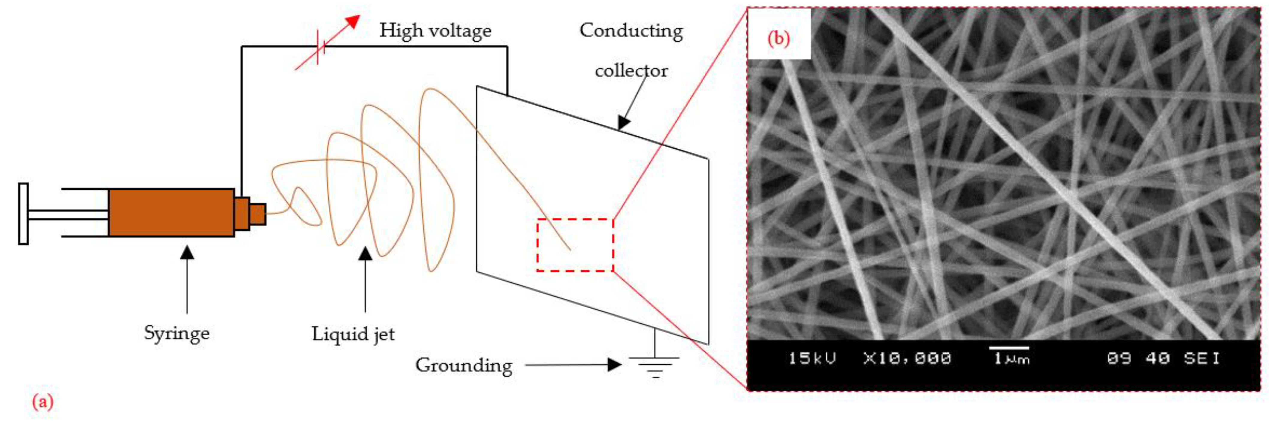
Figure 21. Electrospinning: (a) schematic representation; (b) a typical PAN veil (courtesy of H. He, K. Molnar, Budapest University of Technology and Economics).
References
- Lu, Z.; Li, Y.; Xie, J. Durability of BFRP Bars Wrapped in Seawater Sea Sand Concrete. Compos. Struct. 2021, 255, 112935.
- Guo, R.; Li, C.; Xian, G. Water Absorption and Long-Term Thermal and Mechanical Properties of Carbon/Glass Hybrid Rod for Bridge Cable. Eng. Struct. 2023, 274, 115176.
- Xian, G.; Guo, R.; Li, C.; Wang, Y. Mechanical Performance Evolution and Life Prediction of Prestressed CFRP Plate Exposed to Hygrothermal and Freeze-Thaw Environments. Compos. Struct. 2022, 293, 115719.
- Quaresimin, M.; Schulte, K.; Zappalorto, M.; Chandrasekaran, S. Toughening Mechanisms in Polymer Nanocomposites: From Experiments to Modelling. Compos. Sci. Technol. 2016, 123, 187–204.
- Islam, A.B.M.I.; Kelkar, A.D. Prospects and Challenges of Nanomaterial Engineered Prepregs for Improving Interlaminar Properties of Laminated Composites––a Review. MRS Commun. 2017, 7, 102–108.
- Mouritz, A.P.; Cox, B.N. A Mechanistic Interpretation of the Comparative In-Plane Mechanical Properties of 3D Woven, Stitched and Pinned Composites. Compos. Part A 2010, 41, 709–728.
- Mouritz, A.P. Review of Z-Pinned Composite Laminates. Compos. Part A Appl. Sci. Manuf. 2007, 38, 2383–2397.
- Guzman de Villoria, R.; Hallander, P.; Ydrefors, L.; Nordin, P.; Wardle, B.L. In-Plane Strength Enhancement of Laminated Composites via Aligned Carbon Nanotube Interlaminar Reinforcement. Compos. Sci. Technol. 2016, 133, 33–39.
- Swolfs, Y.; Gorbatikh, L.; Verpoest, I. Fibre Hybridisation in Polymer Composites: A Review. Compos. Part A Appl. Sci. Manuf. 2014, 67, 181–200.
- Lomov, S.V.; Molnár, K. Compressibility of Carbon Fabrics with Needleless Electrospun PAN Nanofibrous Interleaves. Express Polym. Lett. 2016, 10, 25–35.
- Beckermann, G.W.; Pickering, K.L. Mode I and Mode II Interlaminar Fracture Toughness of Composite Laminates Interleaved with Electrospun Nanofibre Veils. Compos. Part A Appl. Sci. Manuf. 2015, 72, 11–21.
- Meireman, T.; Daelemans, L.; Rijckaert, S.; Rahier, H.; Van Paepegem, W.; De Clerck, K. Delamination Resistant Composites by Interleaving Bio-Based Long-Chain Polyamide Nanofibers through Optimal Control of Fiber Diameter and Fiber Morphology. Compos. Sci. Technol. 2020, 193, 108126.
- García-Rodríguez, S.M.; Costa, J.; Rankin, K.E.; Boardman, R.P.; Singery, V.; Mayugo, J.A. Interleaving Light Veils to Minimise the Trade-off between Mode-I Interlaminar Fracture Toughness and in-Plane Properties. Compos. Part A Appl. Sci. Manuf. 2020, 128, 105659.
- Quan, D.; Bologna, F.; Scarselli, G.; Ivankovic, A.; Murphy, N. Interlaminar Fracture Toughness of Aerospace-Grade Carbon Fibre Reinforced Plastics Interleaved with Thermoplastic Veils. Compos. Part A Appl. Sci. Manuf. 2020, 128, 105642.
- Mitchell, G.R. Electrospinning: Principles, Practice and Possibilities; Edited; Tang, B.Z., Abd-El-Aziz, A.S., Craig, S., Dong, J., Masuda, T., Weder, C., Eds.; The Royal Society of Chemistry: Cambridge, UK, 2015; ISBN 978-1849735568.
- Palazzetti, R.; Zucchelli, A. Electrospun Nanofibers as Reinforcement for Composite Laminates Materials—A Review. Compos. Struct. 2017, 182, 711–727.
- Yuris, A.; Dzenis, D.H.R. Delamination Resistant Composites Prepared by Small Diameter Fiber Reinforcement at Ply Interfaces. US Patent No. 6,265,333 B1, July 2001.
- Molnar, K.; Nagy, Z.K. Corona-Electrospinning: Needleless Method for High-Throughput Continuous Nanofiber Production. Eur. Polym. J. 2016, 74, 279–286.
- Molnár, K.; Vas, L.M. Electrospun Composite Nanofibers and Polymer Composites. In Synthetic Polymer-Polymer Composites; Carl Hanser Verlag GmbH & Co. KG: München, Germany, 2012; pp. 301–349.
- ASTM D5528-01; Standard Test Method for Mode I Interlaminar Fracture Toughness of Unidirectional Fiber-Reinforced Polymer Matrix Composites. ASTM: West Conshohocken, PA, USA, 2014.
- ASTM D7905; Standard Test Method for Determination of the Mode II Interlaminar Fracture Toughness of Unidirectional Fiber-Reinforced Polymer Matrix Composites. ASTM: West Conshohocken, PA, USA, 2014.
More