Your browser does not fully support modern features. Please upgrade for a smoother experience.
Please note this is a comparison between Version 1 by Hossein Asgharian and Version 2 by Lindsay Dong.
The cryogenic carbon capture (CCC) process is a promising post-combustion CO2 removal method. This method is very novel compared with conventional and well-developed methods. However, cryogenic carbon capture is not yet commercially available despite its techno-economic benefits. Thus, a model-based design approach for this process can provide valuable information.
- cryogenic carbon capture process
- CCC
- post-combustion CO2 capture
- energy storage
1. Introduction
Due to population expansion, the world’s growing economy, and increasing urbanization, the global energy demand has been increasing exponentially [1]. Although renewables are expanding at high rates, they still cannot satisfy the global energy demand, and because of that, 80% of the current energy demand is still supplied by fossil fuels [2]. The large-scale use of fossil fuels has resulted in air pollution and has deteriorated human health. Based on a recent analysis, global CO2 emissions increased from 33.3 Gigatons/year in 2020 to 34.9 Gigatons/year in 2021 [3]. This prompt increase in global CO2 emissions has brought about numerous intense problems including climate change, global warming, rising sea level, etc. Using renewable energy systems, increasing the efficiency of energy conversion systems, and utilizing CO2 capture technologies are the most practical solutions to regulate CO2 emissions [4]. The latter method is very advantageous, especially in cases such as cement production where the emissions are not avoidable. This method directly targets the emissions at the source and may also remove other pollutants such as NOx. Moreover, the integration of CO2 capture technologies within large industrial plants is convenient and, in some cases, no fundamental change in the plant structure is required. For instance, the cryogenic carbon capture process is a bolt-on retrofit technology since the process just uses electricity, while amine-based processes just need heat and process integration. This technology can also provide an opportunity to supply and store CO2 with high purities which can be used in fuel production or oil recovery processes. Pre-combustion, oxyfuel combustion, and post-combustion are three available CO2 capture methods.
In the case of using the pre-combustion capture method, CO2 is removed from a gas mixture prior to combustion [5]. In other words, hydrocarbon fuel is converted into carbon monoxide and syngas. Then, the generated carbon monoxide reacts with steam to produce hydrogen and CO2. Finally, the produced CO2 is separated from hydrogen that can be combusted without generating any pollutant. This technology is beneficial since it is verified for industrial-scale oil refineries, and it can recover 90–95% of CO2. However, it requires high investment costs. Moreover, high NOx emissions need expensive scrubbers.
In the oxyfuel process, as the name indicates, pure oxygen is used rather than air in the combustion chamber, which results in generating flue gases that consist of almost pure CO2 and vapor. As a result, the separation, and purification of CO2 in this method is very simple [6]. Therefore, CO2 is captured and stored just by the condensation of vapor content in the flue gas and low-temperature purification. When this method is applied, a plant should be equipped with an air separation unit (for oxygen production), a flue gas processing unit as well as a CO2 processing unit. This method can be considered rewarding since it results in very low emissions of NOx, and it has high flexibility for using different types of fuels. Furthermore, achieving 100% combustion of biomass, better behavior of the combustion process, and using a smaller furnace are other attractive features of oxyfuel. However, replacing O2 with air may bring about some challenges. In other words, the energy requirement for oxygen production is high, and keeping the flame stable is challenging [6][7][6,7]. Therefore, the net power production from the plant will be lower and flue gas should be recycled in large quantities to keep the temperature at reasonable levels.
Post-combustion CO2 capture methods include chemical absorption, physisorption, membrane-based capture processes, and cryogenic carbon capture (CCC) processes. In the CCC process, gaseous CO2 can be separated from other components in the flue gas due to their different condensation and desublimation temperatures. This method is gaining more popularity by using less energy [8][9][10][11][12][13][14][15][8,9,10,11,12,13,14,15], capturing CO2 with higher rates and purities, and having faster responses to fluctuations in electricity demand [8][16][17][8,16,17]. Moreover, investigations have indicated that CO2 capture costs can be decreased by 20–40% when the CCC process is used, and it distinctly indicates the economic advantages of the CCC process over other methods [18]. Furthermore, this technology can be easily added to the current industrial emission facilities without any concern regarding chemical solvents or physical sorbents [19]. This method can use natural gas as a refrigerant and because of that, it can store energy in the form of liquid natural gas (LNG). For capturing CO2 using this method, only 12–18% of the power generated in the plant is consumed if the energy storage operates with efficiencies higher than 90% [8]. The energy supplied to the process is mostly used to drive compressors in refrigeration cycles mainly to liquefy natural gas and provide the required LNG for the process. The Cascade liquefaction cycle, mixed refrigerant cycle, and gas expander cycle are the available scenarios to liquefy natural gas and they are discussed in reference [20]. Despite all benefits and advantages of the CCC process, this technology is still in its early stages of development and deals with several challenges such as ice plugging when the flue gas is not water-free [15]. Moreover, this technology can be considered uneconomical when the CO2 mole fraction in the gas mixture is very low. In this case, a large amount of gas other than CO2 should be cooled to condense a very low amount of CO2.
It should be noted that capture conditions have a great impact on the total costs and the required energy used for the separation and compression of CO2 when the CCC process is used [21]. These conditions are the CO2 concentration in flue gases, pressure, temperature, the chemical composition of flue gases, and the required purity of captured CO2. However, among all aforementioned factors, the concentration of CO2 in the flue gas affects the total costs and required energy more effectively.
Techno-economic evaluations have indicated that for large-scale applications, the CCC process costs are comparable with mature conventional monoethanolamine (MEA) absorption technology, while in smaller scales, the costs are significantly lower in the case of using the CCC process rather than MEA [22]. This process can generate extra LNG and store it when renewable electricity is available, or the plant power demand is low. The cooling energy stored in the form of LNG is then recovered during the peak hours when electricity is expensive. As shown in reference [16], using a tank with an LNG storage capacity of 8000 tons in the CCC process may result in alleviating the cycling costs regarding the load-following of power generation units by 85% when the maximum residential electricity demand is 2000 MW.
Exergy analysis, which is a powerful tool for evaluating the performance of thermal systems, can be used to improve the overall thermodynamic efficiency of the CCC process. The results of exergy analysis indicated that compressors and heat exchangers, especially water coolers, generate the total exergy loss in the process [23]. Under this situation, exergy loss of the process can be decreased by minimizing the temperature differences of heat exchangers and using multistage compressors with intercoolers which contribute to enhancing the performance of the process [24].
2. CCC Process
As Figure 1 indicates, the flue gas which leaves the plant should be cooled down to 40 °C (state 1) using a vapor compression refrigeration system or other methods (this temperature is considered as flue gas reference temperature for CO2 capture processes according to NETL). Afterward, the flue gas temperature is further reduced by water cooling which results in reducing the flue gas temperature to 25 °C (state 2). The pressure of the flue gas is then increased to 1.4 bar using a blower (state 3). The flue gas is then cooled to 2 °C (state 4) and its hazardous components including mercury and sulfur dioxide will be washed away (state 11) as it comes to direct contact with chilled water at 1 °C (state 10) and it is directed to a dryer to remove its vapor content. Herein, the pre-processed flue gas (state 5) enters the CCC process to separate its CO2 content. As a result, the separated CO2 is stored in the form of liquid (state 6), while the cold nitrogen-rich gas mixture (state 7) might be used to generate chilled water before being released into the atmosphere (state 8).
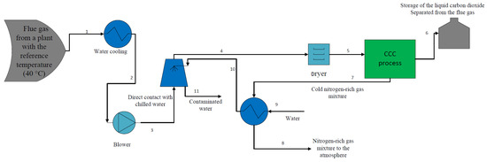
Figure 1.
Flue gas pre-processing before entering CCC process.
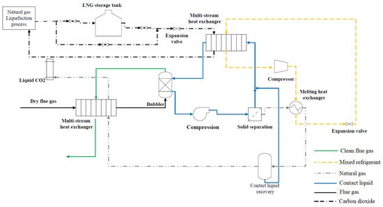
The CCC process is shown in Figure 2. The process flow diagram shown by Figure 2 is similar to the process studied and evaluated by Jensen [8] and Fazlollahi et al. [23]. The dry flue gas after desulfurization enters the CCC process and it is cooled to 175 K by a nitrogen-rich gas mixture which comes from the desublimation heat exchanger and liquid CO2 stream. Then, the flue gas enters a desublimation heat exchanger system, and its temperature is reduced to 154 K by contact liquid. As a result, the CO2 in the flue gas undergoes a phase change and solid particles of CO2 are formed. The clean flue gas leaves the desublimation heat exchanger system from the top and cools the incoming flue gas, while the CO2/contact liquid slurry leaves the heat exchanger from the bottom and it is pressurized by a pump. The solid CO2 particles are separated from the contact liquid by filtration. As Figure 2 indicates, the process requires two refrigeration loops termed the internal and external refrigeration cycles which have the highest energy consumption in the process. The internal refrigeration cycle which may use mixed refrigerant is responsible for providing a part of cooling energy that is used to cool down the contact liquid. As can be seen, the compressed mixed refrigerant is condensed by melting the solid CO2 and increasing its temperature to 233 K. The liquid CO2 stream flashes to generate pure liquid CO2. The liquid-rich CO2 stream cools the incoming flue gas before leaving the CCC process. The external refrigeration loop is also used to produce liquified natural gas to operate the process and provide the rest of the cooling effect for reducing the temperature of contact liquid. The C3MR natural gas liquefaction process is discussed in detail by Wang et al. [25][35]. The liquefied natural gas is used as an intermediate refrigerant to cool the contact liquid which is responsible for the desublimation of CO2 in a heat exchanger. As shown in Figure 2, the LNG leaves the natural gas liquefaction process at a temperature of 179 K. When renewable energy is available and the energy price is low, extra LNG can be generated and stored in a tank. The stored LNG can be used during peak hours when the energy price is high. The LNG which comes from the tank/natural gas liquefaction process is expanded, and its temperature is reduced to 153.6 K; then, it enters a multi-stream heat exchanger to cool the contact liquid. The contact liquid is generally a hydrocarbon mixture, but it can be any other heat transfer fluid that has low viscosity and vapor pressure at cryogenic temperatures [8]. As shown in Figure 2, this liquid is used to separate CO2 in a direct heat exchanger where it is mixed with the flue gases. Using a direct heat exchanger is operationally simple and can desublimate CO2 continuously, while as Figure 2 indicates, a solid separation unit is required to separate solid particles of CO2 from the liquid. In the case of using an indirect heat exchanger, the solid separation unit is not required. However, using this type of heat exchanger adds complexity to the process by causing challenges in cleaning the surface of heat exchangers, requiring maintenance cycles, and avoiding a continuous operation.