Your browser does not fully support modern features. Please upgrade for a smoother experience.
Please note this is a comparison between Version 2 by Sirius Huang and Version 1 by Davide Janner.
In the upcoming space revolutions aiming at the implementation of automated, smart, and self-aware crewless vehicles and reusable spacecraft, sensors play a significant role in the control systems. In particular, fiber optic sensors, with their small footprint and electromagnetic immunity, represent a great opportunity for aerospace applications.
- fiber optics sensor
- radiation
- harsh environment
- FIber Bragg Gratings
- Distributed Fiber sensors
- strain sensors
1. Introduction
Each optical fiber sensor (OFS) class targets different applications based on the sensing mechanism. The main categories of OFS can be identified as point sensors and distributed sensors. In point sensors, a specific and spatially limited part of the fiber, e.g., a Bragg grating, is sensitive to external stimuli, while in distributed ones, all the fiber can act as a detector. This stectionxt compares the main categories and classes of OFS, their sensing mechanism, and their advantages with particular attention applications in the aerospace environment. A detailed description of all the sensing mechanisms is out of scope but can be found in the references herein.
2. Point Sensors
Among the point sensors, the most widely used are fiber Bragg gratings (FBG) and long period gratings (LPG). Even though each type of these OFS has its niche of applications, FBGs are the most studied optical fiber sensors under irradiation and have recently acquired a large market share. The growth forecast of the FBG market in 2028 is expected to reach a global market size of USD 5167.4 million with a 23.9% compound annual growth rate [9][1].
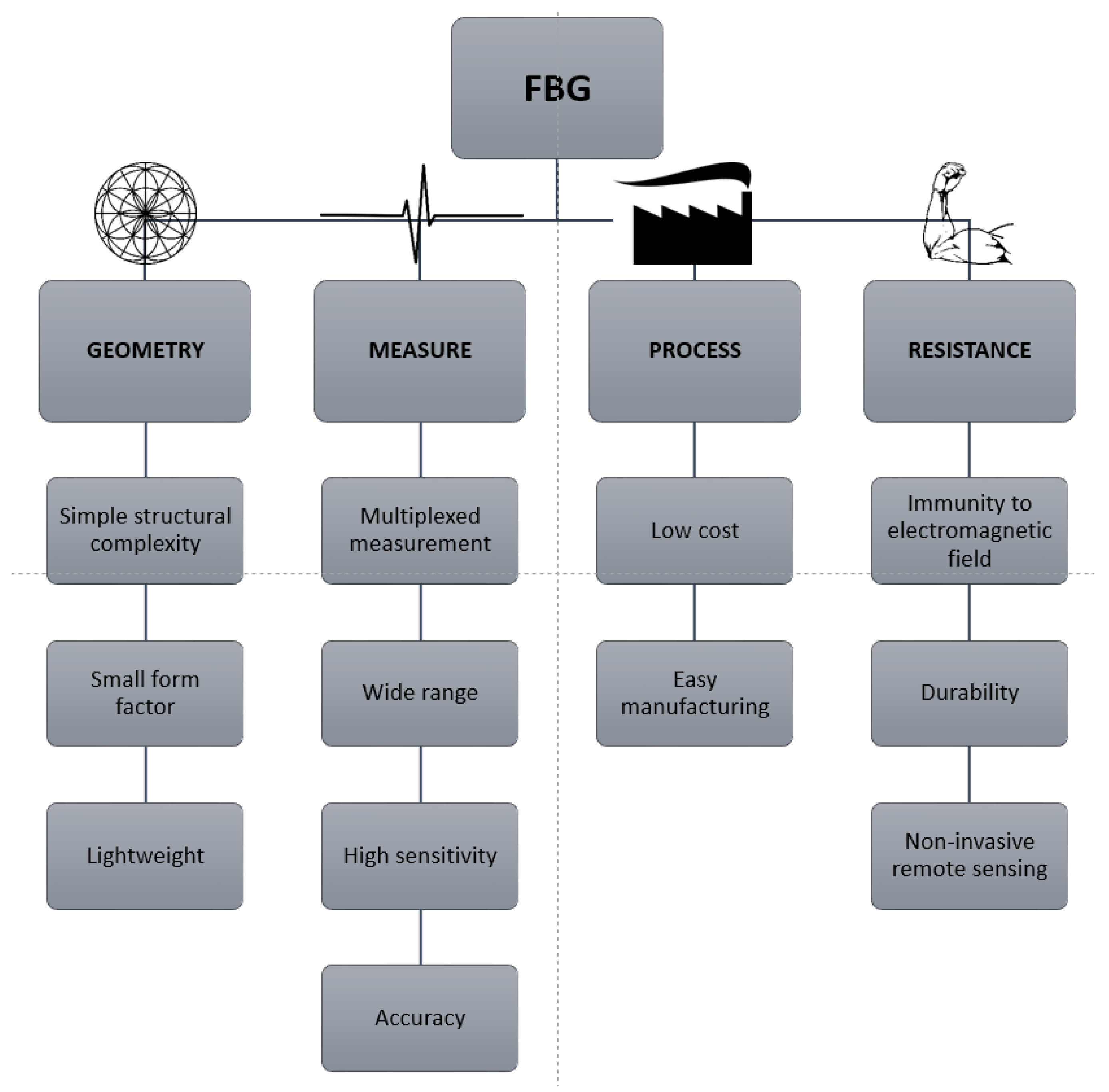
The main advantages of FBGs are summarized in Figure 1, divided by the different features driving the optimal sensor selection in the various applications. Although some of these advantages also apply to distributed sensors, point sensors generally benefit from a lower cost for the interrogators and a much higher sensitivity. The following section reviews the FBG mechanisms and their relevant fabrication techniques, particularly for degradation mechanisms in the presence of radiation.
2.1. Fiber Bragg Gratings
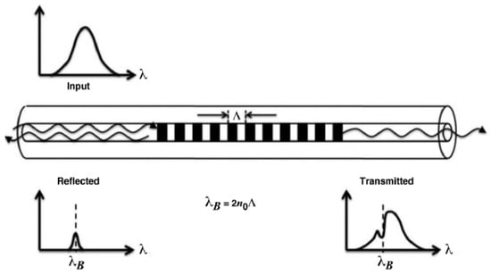
Fiber Bragg gratings can be seen as reflectors for a very narrowband set of wavelengths (typically 0.2–0.5 nm) and are inscribed directly on the optical fiber’s core. The mechanism of reflection is obtained through a periodic variation (period Λ) of the refractive index of the order Δn = 10−4–10−3, which creates a resonance for a specific Bragg wavelength, producing the peak in reflection related to the periodicity Λ (see Figure 2). The relationship between the Bragg wavelength λB and the periodicity of the index variation in fiber Λ is given by:
where n is the effective refractive index in the core of the fiber. On average, the effective refractive index is in the range n = 1.4–1.5, and Bragg gratings are inscribed (or “written”) on a single mode fiber’s core with a period Λ typically from 0.5 μm to a few μm. This allows for precisely tuning the Bragg wavelength in the spectral region of interest for detection and sensing [47][5].
λ
B
= 2
neffΛ,
Λ,
Since the Bragg wavelength depends on the refractive index (see Equation (2)), its change causes the shift of the reflection peak. The phenomena that produce a change in the fiber’s RI are temperature variation and mechanical strain. Calibrating the response of FBG with respect to these two parameters allows them to be used as sensors for these two physical quantities. The typical strain sensitivity of commercial FBGs is about 1 pm/ με and for temperature is 10 pm/°C. Still, these values can be increased by using special pre- and post-treatments, fiber coating, and packaging.
Since the periodic variation in the core has a typical extension of a few mm along the fiber, FBGs are considered single point sensors, meaning that only the written part acts as a transducer and responds to environmental changes. Moreover, the wavelength selective response of the FBG related to the periodicity Λ allows for chaining multiple FBGs at different Λ along the same fiber. Such multiplexed interrogation systems can be seen as multipoint sensors or a quasi-distributed OFS if they are tightly spaced [49][7].
To produce FBGs, different manufacturing techniques have been developed and optimized, and the most common today are [15,47,50,51][2][5][8][9]:
-
Phase mask (PhM);
-
Point by point (PbP);
-
Free space interferometry;
-
Continuous core scanning.
- Phase mask (PhM);
- Point by point (PbP);
- Free space interferometry;
- Continuous core scanning.
The first FBG was obtained by Hill et al. [50][8], who found that the core of standard telecommunication fibers was photosensitive due to the presence of germanium inside the core. Indeed, when exposed to high-intensity visible or UV light, its refractive index would increase proportionally to the light intensity. By modulating the light, it was possible to change the refractive index, creating a periodic pattern.
In the phase mask technique (Figure 3a), a phase mask is interposed between the laser and the fiber, almost in contact with the fiber itself. The mask determines the grating period, producing a diffraction pattern directly related to the spatial modulation of the refractive index to be produced for the FBG. Such a technique is highly reproducible, but each mask can usually produce only gratings working at a specific wavelength, thus requiring multiple masks to cover a reasonable portion of the spectrum where the FBG should operate.
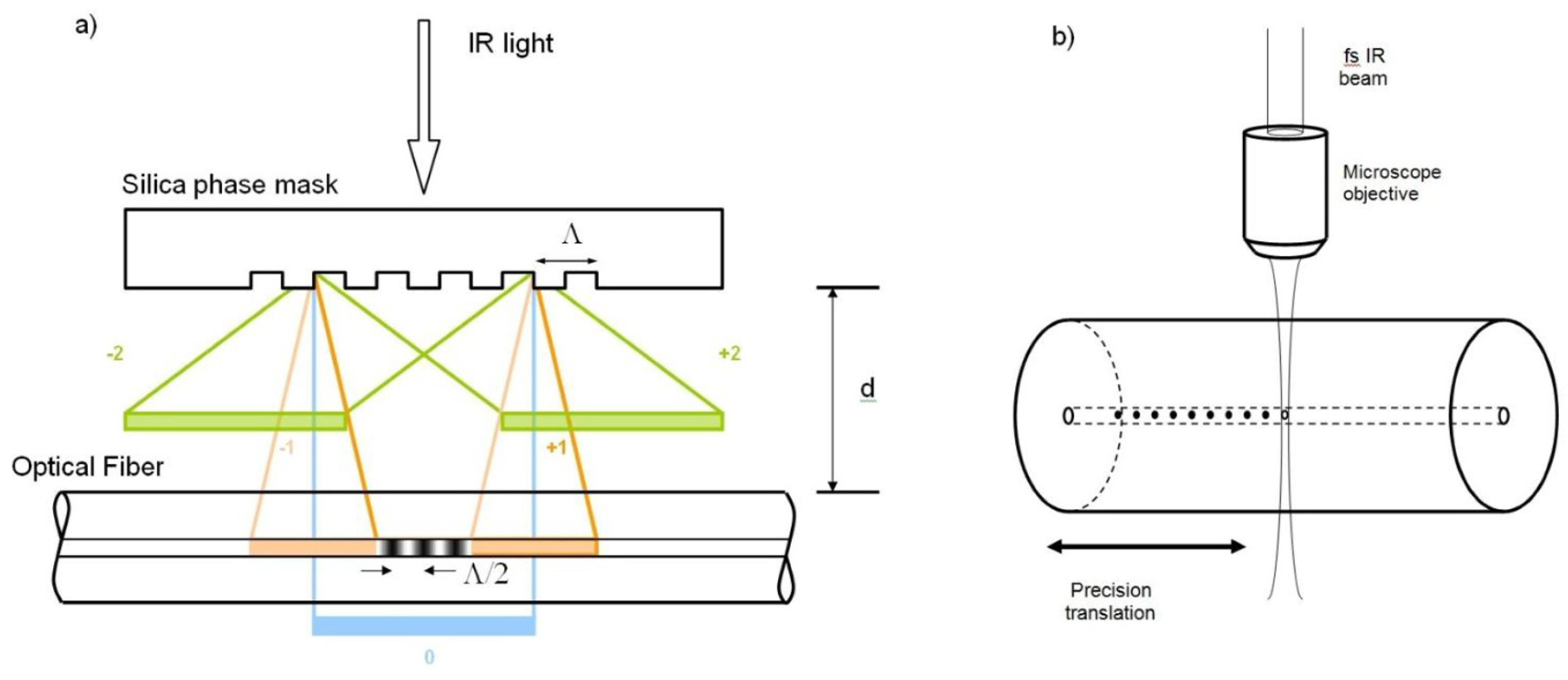
Figure 3.
Schematic representation of two common technologies: (
a
) phase mask inscription with an fs-IR laser and (
The PbP technique generates each grating element controlling the laser parameters and the fiber movement by focusing the laser light on a single point where the index modification is realized. It is based on the nonlinear absorption of an ultrashort laser pulse (Figure 3b). Such absorption produces damage in the material creating zones inside the fiber where the density is slightly changed. By patterning each point, there is fine control of the periodicity of the FBG, leading to a more flexible pattern generation technique. However, such a technique has a much lower throughput with respect to the phase mask one.
OFSs are commonly used for strain and temperature monitoring efficiently, but they can be functionalized for other applications.
2.2. Grating Types
Type I gratings are also referred to as standard gratings, and they were the first type of FBG to be produced. They have a positive refractive index change created through the reaction between the UV/IR laser and the color centers in the core glass [52][10]. The first Bragg produced was Type I-UV and used the oxygen deficiency defect centers in a germanosilicate fiber. To increase the photosensitivity, the core needs to be doped with elements such as Ge [53][11], and if a higher refractive index change is needed, H2 loading can be used. Highly photosensitive Type I hydrogenated fibers are called Type IA.
All Type I FBGs present a temperature-dependent bond-restructuring phenomenon. Indeed, if the FBG is annealed at temperatures below 450 °C, the thermal treatment stabilizes the grating through the thermal depopulation of trapped excited states. However, for temperatures higher than 450 °C, most of the refractive index changes are destroyed by breakage of the formed color centers, especially Type IA.
When a high peak power short-pulsed laser is used to produce the grating over a certain damage threshold of the fiber, Type II FBGs are created. This type of FBG exhibits higher reflectance (<99%) and larger peak width, thus reducing the typical grating length. With UV-lasers, the damage threshold is surpassed, and physical damage is produced between the core and clad, while for IR-lasers, the gratings are realized by the densification of silica. The sensors based on Type II FBGs are more stable and can be used at temperatures over 1000 °C, but they have a lower quality of the reflection spectra, and the fabrication process tends to reduce the overall mechanical strength.
Type I gratings are the former Type IIA, and they are produced with a UV laser on highly stressed Ge-doped fibers. Under certain conditions, a Type I grating starts to grow and then decreases its strength as the gratings saturate. If the exposure continues, a secondary grating starts growing with a negative RI change [54][12]. Type I gratings are stable up to 700 °C [55][13].
Regenerated gratings are obtained from the thermal erasure of the grating. The most common way to produce a regenerated grating is using a Type I grating enhanced through hydrogen loading to increase its photosensitivity. The regeneration process is carried out at room temperature, exposing the FBG to high-pressure hydrogen [56][14]. After UV inscription creates a Type I, the grating is annealed at a temperature between 600 °C and 700 °C, erasing the Type I FBG, but if the heating continues at an even higher temperature, a new grating appears at a longer wavelength. This grating is stable at high temperatures, even above 1000 °C, but its spectral response weakens by order of magnitude, producing a low-reflectivity FBG. The full physical details of the mechanism underlying the regeneration of the FBG are still unknown [57][15].
A femtosecond pulsed infrared laser can be used to induce large index changes thanks to the high peak power [58][16]. The mechanism is different from the UV laser gratings since no color centers are involved. However, the absorption/ionization of a nonlinear multiphoton produces local physical damage, leading to increased density or the generation of physical defects. The properties of these gratings are similar to Type II induced by nanosecond UV lasers. This grating has better spectral performance.
The advantage of this FBG is that it can be inscribed on many types of waveguides, not only silica-based UV-sensitive fibers. Therefore other materials can be used, e.g., sapphire, allowing the production of sensors for highly specialized tasks such as high-temperature sensing above 1750 °C on sapphire fibers [52][10].
2.3. Long Period Gratings
Long period gratings are similar to FBG but with a period typically in the range of 100 μm–1 mm, many times larger than the typical wavelength propagating inside the fiber. LPG promotes the coupling of the light coming from the core to the propagating cladding modes [59][17]. Cladding modes have high attenuation; therefore, the spectrum presents an attenuation band for a specific wavelength related to the periodicity of the LPG. If the environment changes the period or refractive index of the section containing the LPG (typically around 30 mm), these attenuation bands will shift, similar to FBG. LPG sensors have been used for many applications in physical, chemical, and biological sensing [60,61,62,63,64][18][19][20][21][22]. The sensitivity for each measurand depends on the composition of the fiber and the order of the cladding mode coupled; therefore, it is possible to have a single sensor that senses multiple parameters.
There are many fabrication techniques for long period gratings to produce the periodic modulation of optical properties by modifying the core’s refractive index or by physical deformation of the fiber. These techniques are shown in Table 21, and the most common is the UV irradiation of germanosilicate fibers.
Table 21.
Summary of principal fabrication techniques for long period gratings.
| Production Techniques | Reference | |||
|---|---|---|---|---|
| Ultraviolet irradiation | [65] | [23] | ||
| Ion implantation | [66] | [24] | ||
| Irradiation by femtosecond IR laser | [67] | [25] | ||
| Irradiation by CO | 2 | laser | [68] | [26] |
| Diffusion of dopants in the core | [69] | [27] | ||
| Relaxation of mechanical stress | [70] | [28] | ||
| Electrical discharges | [71] | [29] | ||
| Mechanical deformation | [72] | [30] | ||
| Tapering of the fiber | [73] | [31] | ||
| Core deformation | [74] | [32] | ||
| Clad deformation | [75] | [33] |
LPGs attracted the attention of researchers for their use in radiation environments. The first study of their behavior under γ irradiation was by Vasiliev et al. [76][34] in 1998. A complete review was conducted by Esposito et al. [77][35], showing the growing interest in these sensors while, at the same time, underlining the need for further studies on the influence of dose rate and irradiation temperature on their performance.
3. Distributed Optical Fiber Sensors
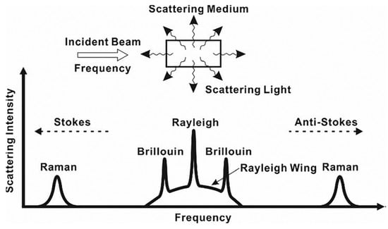
Distributed optical fiber sensors (DOFS) are meant as an improvement in spatial resolution attainable with quasi-distributed system (or multiplexed system) point sensors such as FBGs. The first DOFS system was based on the optical time domain reflectometer and allowed the spatial measurement of any environmental parameter that influenced the fiber’s attenuation with a spatial resolution ranging from 0.1 m to 10 m [78][36]. DOFS are based on a scattering phenomenon that occurs to light during the propagation inside the fiber optics. Currently, based on the used mechanism, three main technologies are available in DOFS: Rayleigh, Brillouin, and Raman. Other technologies exist, such as the optical carrier-based microwave interferometer, but they are infrequent in most of applications [79][37].
Scattering is a random statistical phenomenon that occurs in all angular directions, and in the case of elastic scattering, the frequency of the scattered light is conserved with respect to the input one (Rayleigh). Additionally, if the frequency of light or its energy changes during the scattering process by absorbing or giving energy to the fiber material, then the scattering is called inelastic (Raman and Brillouin). DOFS can thus be classified by what happens to the frequency of the incident light and the occurring scattering mechanism, as shown in Figure 4.
In Rayleigh-based DOFS, a propagating pulse of light in the fiber can maintain its central wavelength, while perturbations along the propagation broaden its optical spectrum. Such elastic scattering originates from material density fluctuations, dopant concentration, or fiber perturbation (strain or temperature) reaching the fiber’s core. Due to its isotropic nature, not all the Rayleigh scattered light goes in the same direction: part follows the initial propagation direction, and part is backscattered (against the propagation direction). These sensors use the backscattered light as in optical time-domain reflectometry (OTDR). When an external perturbation changes the density or dopant concentration locally, its intensity can be measured by the difference signature of the backscattered light before and after [79][37].
There are two approaches that use this phenomenon:
-
Optical time-domain reflectometry is the simplest and measures the intensity of the backscattered light. Each measurand is dependent on the intensity, and the time of arrival of the sensed light is correlated to the distance propagated along the fiber.
-
Optical frequency-domain reflectometry (OFDR) is more complex and is based on the analysis of the measurement of light over two polarization states obtained by the reference light. The position where the variation is happening is related via a complex elaboration of the optical frequency signal.
The advantage of OFDR is that it has greater spatial resolution along the fiber than OTDR, which is at the meter level. In addition, OFDR also has a large dynamic range at the expense of a more complicate and expensive interrogation system [80][38].
To overcome some of the shortcomings of these two techniques, a couple of less-used and still-developing approaches were used. Incoherent optical frequency-domain reflectometry is used to detect with a high spatial resolution over a long range. Indeed, a spatial resolution of 11.2 cm over 151 km was demonstrated [81][39]. Optical low-coherence reflectometry (OLCR) has been developed for the high spatial resolution measurement of small optical components with fine structures thanks to a higher than −95 dB reflection sensitivity [82][40]. It has micrometer-level resolution but a measurement range of less than a few meters.
Brillouin-based DOFS uses inelastic scattering given by energy transfer between photons and acoustic phonons. This interaction leads to a frequency shift of a quantity named Brillouin frequency that is proportional to the effective refractive index, the medium’s acoustic speed, and the incident light’s wavelength. The effective refractive index is the speed of light in a waveguide, such as an optical fiber, divided by the speed of light. This is the propagation speed of waveguide modes. Brillouin frequency varies between 9 and 13 GHz. The acoustic speed is related to the density of the medium; therefore, the change of density by temperature or strain is translated into a change of the Brillouin frequency. These sensors can be used to detect strain and temperature at the same time for tens of km with a typical resolution of 1–10 m.
Brillouin optical time-domain reflectometry (BOTDR) was first developed by Kurashima et al. [83][41] in 1993. This technique is single-ended and similar to Rayleigh’s OTDR but has few variations. Normally, direct detection is used as in Rayleigh DFOS, but there is also heterodyne detection, which employs a reference signal and allows for a longer sensing range and better performance, improving receiver sensitivity [84][42]. In the last years, there have been great improvements in BOTDR achieving great sensitivity for temperature and strain measurement. The maximum range achieved was 100 km, while the spatial resolution went down to 20 cm, and a minimum temperature shift of 0.37 °C and a deformation of 7.4 με were reported [79][37].
Another technique employed in DOFS is the Brillouin optical time-domain analysis (BOTDA), which is based on stimulated Brillouin scattering (SBS). In this configuration, the sensing pulse of light is injected on one end of the fiber, and at the other end, a counter-propagating CW laser is injected [85][43]. The detection technique is similar to standard OTDR systems, and in the same way, BOTDA achieved great improvements in the last years by reaching a longer sensing range of 150 km and a spatial resolution of 10 cm. Such improvements on the range and spatial resolution come at the expenses of the sensor sensitivity. Indeed, the maximum temperature sensitivity obtainable is 1.5 °C and the strain sensitivity of 20 με [79][37]. BOTDA obtained inferior ranges (up to 10 km) but a high spatial resolution of 2 cm, reaching a strain sensitivity of 70 με.
Another technique developed is Brillouin dynamic grating (BDG), which involves dynamically reconfigurable gratings. The BDG paired with PM fibers achieved sensitivities for temperature and a strain of 0.08 °C and 3 με, respectively [86][44]. By lowering the sensitivity, a spatial resolution of 20 cm was obtained [87][45].
Raman-based DOFS exploits an inelastic scattering phenomenon due to the interaction with optical phonons. As for Brillouin, the Raman shift is the difference in frequency between the pump photons and the scattered ones. Raman DOFSs are only sensitive to temperature and not strain and have been recently widely adopted for environmental monitoring [88][46]. Raman scattering has a small cross-section and thus tends to produce weak signals. Therefore, higher laser power must be used while avoiding stimulated Raman scattering. The most-used technique is Raman OTDR, and the highest spatial resolution achieved was of 1.2 cm with a sensing range of 2.8 m [89][47]. Commercially available Raman OTDR has a typical spatial resolution of about 1 m.
Raman OFDR is very similar to OTDR systems and can achieve 2 °C of temperature sensitivity, with a spatial resolution of 1 m on 16 km. The highest temperature accuracy reached was with an OTDR coupled with image processing that achieved 0.004 °C with a spatial resolution of 2 m [90][48].
4. Comparison of Point and Distributed Sensors
Point sensors with FBG gratings present an easy-to-use setup, a low cost, a small form factor, and a wide measurement range, but they are fragile by themselves, and typically, a package is required as protection. Typical FBG sensors have 1.21 pm/με which is relatively low, and in the last years, new advancements were made to increase it up to 31.4 pm/με, as Nawrot et al. [91][49] demonstrated in 2017. Zhang et al. [92][50] developed a Bragg strain sensor with a range of −1500–400 με for high-temperature applications. It is possible to multiplex a point sensor system to achieve quasi-distributed monitoring, but this increases the cost sensibly if large lengths are required to be monitored. The temperature application range for most of FBGs is <450 °C, but new femtosecond FBGs reached stability till 1000 °C, the highest among the OFS. The spatial resolution can be higher than other sensors with less than 1 mm resolution [93][51]. LPG sensors show higher mechanical strength compared to Bragg gratings but generally at a higher cost.
DOFS has the advantage of being already completely distributed, showing high sensitivity and fair precision. Each DOFS’s technology has a different resolution topping for Raman sensor at a resolution of 0.004 °C for temperature and 2 m of spatial resolution. Generally, distributed sensors have a spatial resolution of 1–10 m, with some reaching 100 m. The maximum temperature at which they are stable is normally much lower than for FBGs, and for regular fiber optics, it goes up to 600 °C. Only coherent Rayleigh can reach a spatial resolution in the order of mm.
It is important to remark that, for all of these sensors, in harsh environment applications, it is absolutely necessary to combine at least two technologies to sense strain and temperature simultaneously along two different fibers.
FBG sensors have been considered to substitute older electronic-based sensors in aerospace applications, but DOFS have found much more limited use in such applications. From a radiation response point of view, Bragg sensors have a great advantage: only the grating is the sensitive part, and the interrogation system, affected by radiation, can be installed far away. On the contrary, distributed fibers have much more delicate, sensitive, and expensive electronics, which is significantly more exposed in a radiation environment. In addition, for certain types of fibers (phosphosilicate), DOFS is strongly affected in the measurement along the fiber in the presence of radiation.
Overall, the main advantage of DOFS is the possibility of having a very long sensing fiber (up to tens of km), although for monitoring only a few critical points (up to hundreds), quasi-distributed systems are much simpler, cheaper, and more reliable.
References
- Factors, F. At 23.9% CAGR, Global Fiber Bragg Grating Market Size to Hit USD 5167.4 Million by 2028. Fiber Bragg Grating (FBG) Industry Trends, Growth, Share, Analysis & Forecast Report by Facts & Factors. Available online: https://www.globenewswire.com/news-release/2022/08/03/2491523/0/en/At-23-9-CAGR-Global-Fiber-Bragg-Grating-Market-Size-to-Hit-USD-5167-4-Million-by-2028-Fiber-Bragg-Grating-FBG-Industry-Trends-Growth-Share-Analysis-Forecast-Report-by-Facts-Factors.html (accessed on 21 November 2022).
- Girard, S.; Morana, A.; Ladaci, A.; Robin, T.; Mescia, L.; Bonnefois, J.-J.; Boutillier, M.; Mekki, J.; Paveau, A.; Cadier, B.; et al. Recent Advances in Radiation-Hardened Fiber-Based Technologies for Space Applications. J. Opt. 2018, 20, 093001.
- Zhang, Y.; Peng, H.; Qian, X.; Zhang, Y.; An, G.; Zhao, Y. Recent Advancements in Optical Fiber Hydrogen Sensors. Sens. Actuators B Chem. 2017, 244, 393–416.
- Agrawal, G.P. Fiber-Optic Communication Systems; John Wiley & Sons, Incorporated: Hoboken, NJ, USA, 2010; ISBN 978-0-470-91851-7.
- Hill, K.O.; Meltz, G. Fiber Bragg Grating Technology Fundamentals and Overview. J. Light. Technol. 1997, 15, 1263–1276.
- Emmons, M.; Carman, G.; Mohanchandra, K.; Richards, W.L. Characterization and Birefringence Effect on Embedded Optical Fiber Bragg Gratings. Proc. SPIE 2009, 7295, 119–129.
- Kersey, A.D.; Berkoff, T.A.; Morey, W.W. Multiplexed Fiber Bragg Grating Strain-Sensor System with a Fiber Fabry–Perot Wavelength Filter. Opt. Lett. 1993, 18, 1370.
- Hill, K.O.; Fujii, Y.; Johnson, D.C.; Kawasaki, B.S. Photosensitivity in Optical Fiber Waveguides: Application to Reflection Filter Fabrication. Appl. Phys. Lett. 1978, 32, 647–649.
- Williams, R.J.; Krämer, R.G.; Nolte, S.; Withford, M.J. Femtosecond Direct-Writing of Low-Loss Fiber Bragg Gratings Using a Continuous Core-Scanning Technique. Opt. Lett. 2013, 38, 1918–1920.
- Mihailov, S.J. Fiber Bragg Grating Sensors for Harsh Environments. Sensors 2012, 12, 1898–1918.
- Tsai, T.-E.; Williams, G.M.; Friebele, E.J. Index Structure of Fiber Bragg Gratings in Ge–SiO2 Fibers. Opt. Lett. 1997, 22, 224–226.
- Xie, W.X.; Niay, P.; Bernage, P.; Douay, M.; Bayon, J.F.; Georges, T.; Monerie, M.; Poumellec, B. Experimental Evidence of Two Types of Photorefractive Effects Occuring during Photoinscriptions of Bragg Gratings within Germanosilicate Fibres. Opt. Commun. 1993, 104, 185–195.
- Niay, P.; Bernage, P.; Legoubin, S.; Douay, M.; Xie, W.X.; Bayon, J.F.; Georges, T.; Monerie, M.; Poumellec, B. Behaviour of Spectral Transmissions of Bragg Gratings Written in Germania-Doped Fibres: Writing and Erasing Experiments Using Pulsed or Cw Uv Exposure. Opt. Commun. 1994, 113, 176–192.
- Lemaire, P.J.; Atkins, R.M.; Mizrahi, V.; Reed, W.A. High Pressure H2 Loading as a Technique for Achieving Ultrahigh UV Photosensitivity and Thermal Sensitivity in GeO2 Doped Optical Fibres. Electron. Lett. 1993, 29, 1191–1193.
- Lindner, E.; Canning, J.; Chojetzki, C.; Brückner, S.; Becker, M.; Rothhardt, M.; Bartelt, H. Post-Hydrogen-Loaded Draw Tower Fiber Bragg Gratings and Their Thermal Regeneration. Appl. Opt. 2011, 50, 2519–2522.
- Davis, K.M.; Miura, K.; Sugimoto, N.; Hirao, K. Writing Waveguides in Glass with a Femtosecond Laser. Opt. Lett. 1996, 21, 1729–1731.
- James, S.W.; Tatam, R.P. Optical Fibre Long-Period Grating Sensors: Characteristics and Application. Meas. Sci. Technol. 2003, 14, R49.
- Hromadka, J.; Korposh, S.; Partridge, M.C.; James, S.W.; Davis, F.; Crump, D.; Tatam, R.P. Multi-Parameter Measurements Using Optical Fibre Long Period Gratings for Indoor Air Quality Monitoring. Sens. Actuators B Chem. 2017, 244, 217–225.
- Chiavaioli, F.; Baldini, F.; Tombelli, S.; Trono, C.; Giannetti, A. Biosensing with Optical Fiber Gratings. Nanophotonics 2017, 6, 663–679.
- Janczuk-Richter, M.; Dominik, M.; Roźniecka, E.; Koba, M.; Mikulic, P.; Bock, W.J.; Łoś, M.; Śmietana, M.; Niedziółka-Jönsson, J. Long-Period Fiber Grating Sensor for Detection of Viruses. Sens. Actuators B Chem. 2017, 250, 32–38.
- Sensitivity Enhancing of Transition Mode Long-Period Fiber Grating as Methane Sensor Using High Refractive Index Polycarbonate/Cryptophane A Overlay Deposition—ScienceDirect. Available online: https://www.sciencedirect.com/science/article/abs/pii/S0925400514012222 (accessed on 21 November 2022).
- Esposito, F.; Srivastava, A.; Iadicicco, A.; Campopiano, S. Multi-Parameter Sensor Based on Single Long Period Grating in Panda Fiber for the Simultaneous Measurement of SRI, Temperature and Strain. Opt. Laser Technol. 2019, 113, 198–203.
- Bhatia, V.; Vengsarkar, A.M. Optical Fiber Long-Period Grating Sensors. Opt. Lett. 1996, 21, 692–694.
- Fujimaki, M.; Ohki, Y.; Brebner, J.L.; Roorda, S. Fabrication of Long-Period Optical Fiber Gratings by Use of Ion Implantation. Opt. Lett. 2000, 25, 88–89.
- Kondo, Y.; Nouchi, K.; Mitsuyu, T.; Watanabe, M.; Kazansky, P.G.; Hirao, K. Fabrication of Long-Period Fiber Gratings by Focused Irradiation of Infrared Femtosecond Laser Pulses. Opt. Lett. 1999, 24, 646–648.
- Drozin, L.; Fonjallaz, P.-Y.; Stensland, L. Long-Period Fibre Gratings Written by CO2 Exposure of H2-Loaded, Standard Fibres. Electron. Lett. 2000, 36, 742.
- Dianov, E.M.; Karpov, V.I.; Grekov, M.V.; Golant, K.M.; Vasiliev, S.A.; Medvedkov, O.I.; Khrapko, R.R. Thermo-Induced Long-Period Fibre Gratings. In Proceedings of the Integrated Optics and Optical Fibre Communications, 11th International Conference on, and 23rd European Conference on Optical Communications (Conf. Publ. No.: 448), Edinburgh, UK, 22–25 September 1997; Volume 2, pp. 53–56.
- Kim, C.-S.; Han, Y.; Lee, B.H.; Han, W.-T.; Paek, U.-C.; Chung, Y. Induction of the Refractive Index Change in B-Doped Optical Fibers through Relaxation of the Mechanical Stress. Opt. Commun. 2000, 185, 337–342.
- Palai, P.; Satyanarayan, M.N.; Das, M.; Thyagarajan, K.; Pal, B.P. Characterization and Simulation of Long Period Gratings Fabricated Using Electric Discharge. Opt. Commun. 2001, 193, 181–185.
- Jiang, Y.; Li, Q.; Lin, C.-H.; Lyons, E.; Tomov, I.; Lee, H.P. A Novel Strain-Induced Thermally Tuned Long-Period Fiber Grating Fabricated on a Periodic Corrugated Silicon Fixture. IEEE Photonics Technol. Lett. 2002, 14, 941–943.
- Kakarantzas, G.; Dimmick, T.E.; Birks, T.A.; Roux, R.L.; Russell, P.S.J. Miniature All-Fiber Devices Based on CO2 Laser Microstructuring of Tapered Fibers. Opt. Lett. 2001, 26, 1137–1139.
- Narayanan, C.; Presby, H.M.; Vengsarkar, A.M. Band-Rejection Fiber Filter Using Periodic Core Deformation. In Proceedings of the Optical Fiber Communications Conference, OFC, San Jose, CA, USA, 25 February 1996; pp. 267–269.
- Lin, C.-Y.; Chern, G.-W.; Wang, L.A. Periodical Corrugated Structure for Forming Sampled Fiber Bragg Grating and Long-Period Fiber Grating with Tunable Coupling Strength. J. Light. Technol. 2001, 19, 1212–1220.
- Vasiliev, S.A.; Dianov, E.M.; Golant, K.M.; Medvedkov, O.I.; Tomashuk, A.L.; Karpov, V.I.; Grekov, M.V.; Kurkov, A.S.; Leconte, B.; Niay, P. Performance of Bragg and Long-Period Gratings Written in N- and Ge-Doped Silica Fibers under/Spl Gamma/-Radiation. IEEE Trans. Nucl. Sci. 1998, 45, 1580–1583.
- Esposito, F.; Srivastava, A.; Campopiano, S.; Iadicicco, A. Radiation Effects on Long Period Fiber Gratings: A Review. Sensors 2020, 20, 2729.
- Rogers, A. Distributed Optical-Fibre Sensing. Meas. Sci. Technol. 1999, 10, R75.
- Lu, P.; Lalam, N.; Badar, M.; Liu, B.; Chorpening, B.T.; Buric, M.P.; Ohodnicki, P.R. Distributed Optical Fiber Sensing: Review and Perspective. Appl. Phys. Rev. 2019, 6, 41302.
- Ding, Z.; Wang, C.; Liu, K.; Jiang, J.; Yang, D.; Pan, G.; Pu, Z.; Liu, T. Distributed Optical Fiber Sensors Based on Optical Frequency Domain Reflectometry: A Review. Sensors 2018, 18, 1072.
- Incoherent Optical Frequency Domain Reflectometry Based on a Kerr Phase-Interrogator. Available online: https://opg.optica.org/oe/fulltext.cfm?uri=oe-22-13-15370&id=294064 (accessed on 21 November 2022).
- Mechels, S.; Takada, K.; Okamoto, K. Optical Low-Coherence Reflectometer for Measuring WDM Components. IEEE Photonics Technol. Lett. 1999, 11, 857–859.
- Kurashima, T.; Horiguchi, T.; Izumita, H.; Furukawa, S.; Koyamada, Y. Brillouin Optical-Fiber Time Domain Reflectometry. IEICE Trans. Commun. 1993, E76-B, 382–390.
- Kee, H.H.; Lees, G.P.; Newson, T.P. All-Fiber System for Simultaneous Interrogation of Distributed Strain and Temperature Sensing by Spontaneous Brillouin Scattering. Opt. Lett. 2000, 25, 695–697.
- Horiguchi, T.; Tateda, M. BOTDA-Nondestructive Measurement of Single-Mode Optical Fiber Attenuation Characteristics Using Brillouin Interaction: Theory. J. Light. Technol. 1989, 7, 1170–1176.
- Zou, W.; He, Z.; Hotate, K. Complete Discrimination of Strain and Temperature Using Brillouin Frequency Shift and Birefringence in a Polarization-Maintaining Fiber. Opt. Express 2009, 17, 1248–1255.
- Dong, Y.; Chen, L.; Bao, X. High-Spatial-Resolution Time-Domain Simultaneous Strain and Temperature Sensor Using Brillouin Scattering and Birefringence in a Polarization-Maintaining Fiber. IEEE Photonics Technol. Lett. 2010, 22, 1364–1366.
- Watson, G.H.; Daniels, W.B.; Wang, C.S. Measurements of Raman Intensities and Pressure Dependence of Phonon Frequencies in Sapphire. J. Appl. Phys. 1981, 52, 956–958.
- Glombitza, U.; Brinkmeyer, E. Coherent Frequency-Domain Reflectometry for Characterization of Single-Mode Integrated-Optical Waveguides. J. Light. Technol. 1993, 11, 1377–1384.
- Soto, M.A.; Ramírez, J.A.; Thévenaz, L. Intensifying the Response of Distributed Optical Fibre Sensors Using 2D and 3D Image Restoration. Nat. Commun. 2016, 7, 10870.
- Nawrot, U.; Geernaert, T.; Pauw, B.D.; Anastasopoulos, D.; Reynders, E.; Roeck, G.D.; Berghmans, F. Development of a Mechanical Strain Amplifying Transducer with Bragg Grating Sensor for Low-Amplitude Strain Sensing. Smart Mater. Struct. 2017, 26, 75006.
- Zhang, L.; Liu, Y.; Gao, X.; Xia, Z. High Temperature Strain Sensor Based on a Fiber Bragg Grating and Rhombus Metal Structure. Appl. Opt. 2015, 54, E109–E112.
- Murayama, H.; Wada, D.; Igawa, H. Structural Health Monitoring by Using Fiber-Optic Distributed Strain Sensors with High Spatial Resolution. Photonic Sens. 2013, 3, 355–376.
More