Increasing energy usage efficiency requires enhanced heat energy recuperation between process streams in the industry and civic sector with waste heat utilization. The condensation of different vapours is the process encountered in many industrial applications. Increasing the heat recuperation in this process is possible with efficient heat transfer equipment, among which a Plate Heat Exchanger (PHE) is at the leading position. PHE in processes of vapour condensation is the fast-developing type of heat transfer equipment. Their main advantages compared to traditional shell-and-tube heat exchangers are compactness, small mass and inner volume, and enhanced heat transfer. The construction of PHE can be adapted to the required conditions of specific applications as condensers.
- plate heat exchanger
- heat transfer
- vapor
- condensation
- pressure drop
- energy efficiency
1. Introduction
2. Heat Transfer in Two-Phase Condensing Flows Inside PHE Channels
The structure of two-phase flow in the PHE channels of complex geometry is very different from that in tubes and flat wall channels. It does not allow for the calculation of heat transfer coefficients in condensation processes inside the PHE channels and the correlations published for tubes. The possibilities of theoretical process investigation in such channels of complicated geometry are very limited, and the main method of obtaining reliable correlations is an experimental study. Farahani et al. [4] discussed publications on experimental investigations of refrigerants condensation in PHE channels. The main difference with condensation in tubular heat exchangers is a much more complex flow structure in the PHE channels than in tubes. This complicates the process and makes it difficult to obtain correlations for thermal and hydraulic design. In the majority of industrial applications of condensing pure vapours, the film condensation takes place and the thermal resistance on the vapour side is created by the heat transfer in the film of condensed liquid. It was observed that most of the analyzed studies are made for average heat transfer coefficients, and local data are very limited. The accuracy of correlations presented in some of these papers is estimated by comparison with a databank of 532 data points. These are selected from six experimental kinds of research on the condensation of three refrigerants in channels of different PHEs. All correlations are most accurate for the data on which they were received. Even the best accuracy correlations predict all data banks with an error of up to 50% and even more. In all considered papers, the averaged full PHE surface area heat transfer coefficients are studied, and their correlations as a function of averaged process parameters in the channels are used. In vapour condensation inside the channels, all process parameters are changing considerably along the heat transfer surface, with the vapour part gradually transforming to liquid condensate. The flowrate of the gaseous phase decreases which leads to smaller vapour velocities, a decline of shear stresses between phases and a lessening of their interaction. More detailed information about local process parameters is required to account for these phenomena. Wang and Kabelac [5] experimentally investigated quasi-local parameters in the process of R1234ze(E) and R134a refrigerants condensation inside the channels of gasketed PHE, with the length of the plates’ main corrugated area 0.72 m. The corrugation angles on alternated plates forming channels were 27° and 63°, which creates a mixed channel with an average corrugation angle of 45°. The surface of the plates in one channel (of a total of four) had special micro pits on the vapour side. The local parameters were measured using thermocouples installed in 7 places along the channel, on the cooling water side and on the plate wall. The comparison of local heat transfer coefficients with correlations proposed by different scholars has shown considerable discrepancies, with the root mean square error (RMSE) of 41.2% in the best case. A new correlation for local heat transfer was proposed giving RMSE = 14.5%. In a further study with the same PHE [6], the correlation for heat transfer was modernised, giving RMSE = 10% in comparison with experimental data on local heat transfer. The attempt to correlate average heat transfer coefficients in the condensation of vapour mixture of water-ethanol in PHE channels was made by Zhou et al. [7]. As a result, the correlation as a function of the Nu number from the Sherwood number (Sh), Re number and three other dimensionless numbers was received, predicting experimental data with deviations up to 32%. The strange modification of the Sh number and Re in power 5.6288 renders its low credibility. Another strange correlation with an average deviation smaller than 5% was additionally proposed. Bringing forward information known since 1993 [8], the trick of correlating the average Nusselt number by function from the heat load (to which Re of the condensed liquid is directly proportional) is divided on the same temperature difference at which the heat transfer coefficient is determined. It gives small deviations of data, but little real information that can be simply lost with such a way of data treatment.3. Pressure Drop in Two-Phase Condensing Flows Inside PHE Channels
The pressure drop of two-phase flow condensing in PHE channels can considerably influence the design of PHE, as in many cases of industrial applications, it is strictly limited. Besides, it leads to the change of pressure inside the channel and to a diminishing temperature of vapour saturation, decreasing the driving force of the heat transfer process. The change of static pressure in condensing the two-phase flow inside the PHE channel is determined by Equation:
where
Pmx
dPTP/dx
ρmx
3
Wmx
x is coordinated along thechannel, m.
3.1. Correlations with Averaged Process Parameters
A comprehensive review of research results in a pressure drop in condensation inside PHE channels is presented in the paper [9]. The accuracy of different correlations is analysed based on a comparison with the database, including 1590 pressure drop data. Different approaches for the prediction of a pressure drop in condensing the two-phase flow were divided into three groups: (1) homogeneous flow model with a calculation of friction factor for two-phase flow; (2) separated phases flow model proposed by Lockhart and Martinelli for tubes [10]; (3) kinetic energy model, that considers PHE as local hydraulic resistance with averaged flow density. Even the correlation proposed in the paper [9], which appeared the most accurate, has deviations of more than 50% for 12.5% of the considered database with RMSE = 49.9%. Such accuracy is not suitable for the design of PHEs in different process conditions that are required for their inclusion in optimisation software for heat exchanger networks (HENs), e.g., those considered in the paper by Wang et al. [11]. To improve prediction accuracy in [12], only conditions specific for ORC and heat pump systems were considered, and a new correlation was proposed.3.2. Pressure Drop Prediction with Local Process Parameters
In all considered studies, the average condensation process parameters were used in obtaining pressure drop correlations in PHE channels. As was discussed in Section 2, iIt does not permit accounting for the change of local process parameters, and does not permit accurately correlating the data obtained on PHEs of different construction and sizes produced by different manufacturers. The lack of theoretical background does not permit the widening of the obtained correlation to the condensation of other vapours with different thermo-physical properties. To avoid these drawbacks of averaging solutions, modelling of the condensation process in brazed BPHE in [13] was used for discretisation of the PHE channel on small zones along its length. For pressure drop calculation, the approach of Lockhart-Martinelli was used, which gave acceptable accuracy results.
4. The Structure of Two-Phase Condensing Flows Inside PHE Channels
The two-phase flow structure is one of the main factors determining the character of heat transfer and pressure losses during the condensation of vapours in PHE channels. Its change can considerably influence the relations when determining the process intensity that corresponds to certain flow models. The comprehensive analysis of different downward flow structures during vapour condensation in PHE channels was made in the paper by Tao et al. [14], based on previously published research results on visualisation studies of two-phase flows, e.g., the paper by Grabenstein et al. [15]. There are different overall flows depending on the corrugation angle: crossing flow along the furrows at a small corrugations angle and longitudinal wavy flow when the corrugation angle is large. The flow patterns of the two-phase flow depend on vapour quality, flow rates, and liquid and vapour properties. There are partial film flow, film flow, annular, slug-annular, churn, slug, slug-bubbly, regular-bubbly and dispersed-bubbly flow patterns. The combined flow patterns maps are built and compared to those for the downward two-phase flow in tubes, which cannot be directly used for PHE. The condensation mechanisms controlled by gravity and by convection are discussed, and the factors influencing them are determined. The majority of studies considered in [14] are performed with water and air as two phases. Only in paper [15] was the condensation of R365mfc refrigerant studied, as in an earlier work [16] for PHE with plates corrugation angle 27° and 63°. The results of the flow visualisation study for the condensation of ammonia in PHE channels with corrugations angle 63° are reported in [17]. The main flow patterns observed were partial and full film flow, the transition between which was mainly determined by wetting properties. Only qualitative characterisation was made with graphs, with no quantitative correlations. The qualitative picture was also received in the visualisation study of water–air two-phase flow reported by Buscher [18] for the PHE channel with plates corrugation angle 75°. The partial and full film flow, homogenous and bubble flow patterns were observed. With the rapid development of computer technologies, the computational fluid dynamic (CFD) became a powerful tool for detailed analysis of hydrodynamics in different flows, now including two-phase flows in the PHE channels of complicated three-dimensional geometry. The CFD modelling of two-phase water–air upward flow in the PHE channel was reported by Zhu and Haglind [19]. The results of different flow patterns were confirmed by comparison with experimental data on flow visualisation available in the literature. The results are mostly concerned with boiling, but are also interesting as an example of two-phase flow modelling. The information on the flow structure of the condensing two-phase flow and its change along the channels is important in developing reliable mathematical models for process simulation in PHE and their design in industrial applications. Besides, it is valuable for the development of new constructions specific to this process. For example, increased volume flow rates of vapour at the condenser inlet can require enlarging cross-section areas of inlet collector and ports, leading to the development of specialised PHE, e.g., AlfaCond [20] or BPHE with different channel gaps. The significant change in flow velocities can be adopted by varying cross-section areas of channels [21] and its proper correlation with a channel for cooling media.5. Conclusions
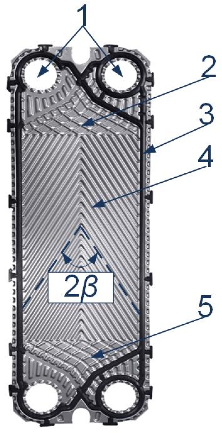
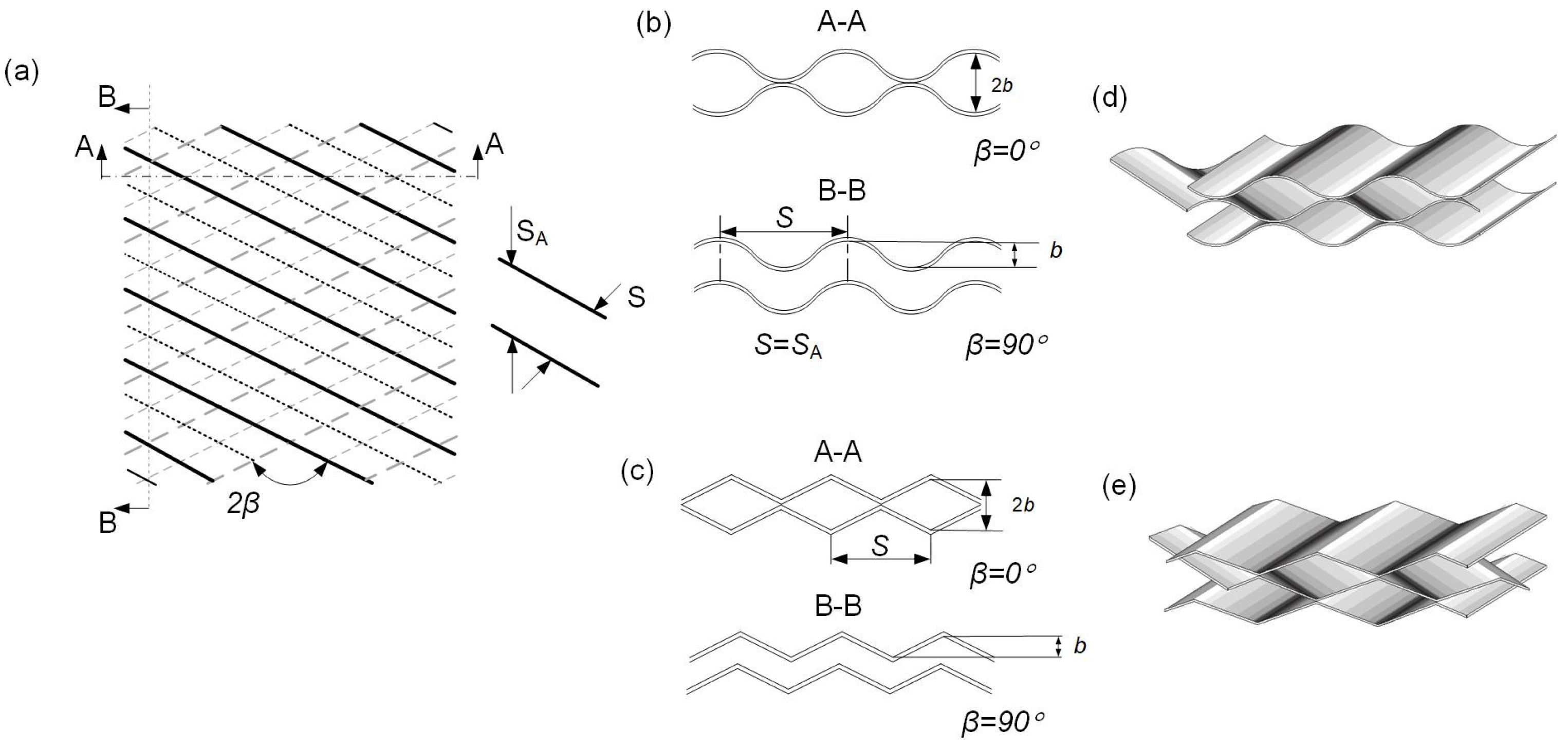
Flow structure in PHE and heat transfer during condensation is considerably different from flows in smooth tubes and flat-wall channels. It stipulates the studies on heat transfer enhancement and pressure losses in condensing two-phase flows inside PHE channels of complicated geometry. Presently, the plates with inclined corrugations are mostly used in PHEs for vapour condensation. Considerable numbers of experiments on condensation of different vapours in the PHE channels are found in the literature. The present analysis considered a total number of 3272 data points on heat transfer from 32 papers, with distribution on the number of studies by investigating the corrugation angle in PHE and the nature of condensing vapour. There is a big difference in the experimental point numbers obtained for different corrugation angles and different vapours. The biggest numbers of studies are for the corrugation angles equal to 65 degrees and for different kinds of refrigerants. Such uneven distribution is one of the explanations for the difficulties of all data generalisation by the single correlation, based on averaged process parameters. The corrugation inclination angle to the main flow direction is the main factor affecting PHE performance at the same corrugation height and form. The investigated range of corrugation angles that can have been studied in PHE is from 27° to 75°. The increase of corrugation angles in this range by data in the majority of research is leading to an increase of heat transfer intensity during vapour condensation, but also involves the rise in friction factor. There are considerable differences in approaches to modelling, design and construction optimisation between PHE condensers for steam and some other process vapours and for refrigerants, in which vapours densities at working conditions are usually much higher than the density of steam and process vapours in industrial applications. In recent years the main subjects of studies on condensation in PHE channels are different refrigerants. It is explained by a fast development in heat pumps and ORC technologies, and the need for adequate correlations for prediction of PHE performance in such applications.References
- Chong, C.T.; Fan, Y.V.; Lee, C.T.; Klemeš, J.J. Post COVID-19 energy sustainability and carbon emissions neutrality. Energy 2022, 241, 122801.
- Klemeš, J.J.; Arsenyeva, O.; Kapustenko, P.; Tovazhnyanskyy, L. Compact Heat Exchangers for Energy Transfer Intensification: Low Grade Heat and Fouling Mitigation; CRC Press: Boca Raton, FL, USA, 2015.
- Arsenyeva, O.P.; Tovazhnyanskyy, L.L.; Kapustenko, P.O.; Khavin, G.L.; Yuzbashyan, A.P.; Arsenyev, P.Y. Two types of welded plate heat exchangers for efficient heat recovery in industry. Appl. Therm. Eng. 2016, 105, 763–773.
- Vakili-Farahani, F.; Amalfi, R.L.; Thome, J.R. Two-phase heat transfer and pressure drop within plate heat exchangers. Encyclopedia of Two-Phase Heat Transfer and Flow II: Special Topics and Applications. 2016, pp. 145–215. Available online: https://www.worldscientific.com/ (accessed on 15 November 2022).
- Wang, R.; Kabelac, S. Condensation quasi-local heat transfer and frictional pressure drop of R1234ze (E) and R134a in a micro-structured plate heat exchanger. Appl. Therm. Eng. 2021, 197, 117404.
- Wang, R.; Sun, T.; Polzin, A.E.; Kabelac, S. Experimental investigation of the two-phase local heat transfer coefficients for condensation of R134a in a micro-structured plate heat exchanger. Heat Mass Transf. 2022, 58, 1–18.
- Zhou, W.; Hu, S.; Ma, X.; Zhou, F. Condensation heat transfer correlation for water-ethanol vapor mixture flowing through a plate heat exchanger. Heat Mass Transf. 2018, 54, 3025–3033.
- Wang, Z.Z.; Zhao, Z.N. Analysis of performance of steam condensation heat transfer and pressure drop in plate condensers. Heat Transf. Eng. 1993, 14, 32–41.
- Tao, X.; Ferreira, C.A.I. Heat transfer and frictional pressure drop during condensation in plate heat exchangers: Assessment of correlations and a new method. Int. J. Heat Mass Transf. 2019, 135, 996–1012.
- Lockhart, R.W.; Martinelli, R.C. Proposed correlation of data for isothermal two-phase, two-component flow in pipes. Chem. Eng. Prog. 1949, 45, 39–48.
- Wang, B.; Arsenyeva, O.; Zeng, M.; Klemeš, J.J.; Varbanov, P.S. An advanced Grid Diagram for heat exchanger network retrofit with detailed plate heat exchanger design. Energy 2022, 248, 123485.
- Zhang, J.; Elmegaard, B.; Haglind, F. Condensation heat transfer and pressure drop correlations in plate heat exchangers for heat pump and organic Rankine cycle systems. Appl. Therm. Eng. 2021, 183, 116231.
- Gullapalli, V.S. Estimation of Thermal and Hydraulic Characteristics of Compact Brazed Plate Heat Exchangers. Ph.D. Thesis, Lund University, Lund, Sweden, 2013.
- Tao, X.; Nuijten, M.P.; Ferreira, C.A.I. Two-phase vertical downward flow in plate heat exchangers: Flow patterns and condensation mechanisms. Int. J. Refrig. 2018, 85, 489–510.
- Grabenstein, V.; Polzin, A.-E.; Kabelac, S. Experimental investigation of the flow pattern, pressure drop and void fraction of two-phase flow in the corrugated gap of a plate heat exchanger. Int. J. Multiph. Flow 2017, 91, 155–169.
- Grabenstein, V.; Kabelac, S. Experimental and theoretical analysis of the local condensation heat transfer in a plate heat exchanger. J. Phys. Conf. Ser. 2012, 395, 012169.
- Tao, X.; Dahlgren, E.; Leichsenring, M.; Ferreira, C.A.I. NH3 condensation in a plate heat exchanger: Experimental investigation on flow patterns, heat transfer and frictional pressure drop. Int. J. Heat Mass Transf. 2020, 151, 119374.
- Buscher, S. Visualization and modelling of flow pattern transitions in a cross-corrugated plate heat exchanger channel with uniform two-phase distribution. Int. J. Heat Mass Transf. 2019, 144, 118643.
- Zhu, X.; Haglind, F. Computational fluid dynamics modeling of liquid–gas flow patterns and hydraulics in the cross-corrugated channel of a plate heat exchanger. Int. J. Multiph. Flow 2020, 122, 103163.
- AlfaLaval. AlfaCond Condensers. Available online: https://www.alfalaval.com/microsites/gphe/types/alfacond/ (accessed on 10 November 2022).
- Arsenyeva, O.; Tovazhnyansky, L.; Kapustenko, P.; Perevertaylenko, O.; Khavin, G. Investigation of the new corrugation pattern for low pressure plate condensers. Appl. Therm. Eng. 2011, 31, 2146–2152.