Your browser does not fully support modern features. Please upgrade for a smoother experience.
Please note this is a comparison between Version 2 by Rita Xu and Version 1 by Zewei Yuan.
Diamond dicing blades are profound cutting tools that find their applications in semiconductor back-end packaging and assembly processes. To fully appreciate the benefits of the dicing blade technique for precision machining, a deeper understanding is required.
- dicing blades
- precision machining
- surface roughness
1. Introduction
Dicing blades extend the capabilities of the traditional semiconductor process by allowing multiple microelectromechanical devices to be mounted on a single silicon wafer. Microelectromechanical systems (MEMSs) coupled with integrated circuitry (IC), infrared (IR) filter devices, and electromechanical components necessitate the profiling of hard and brittle materials such as silicon, silicon carbide and sintered silicon carbide (SiC and SSiC, respectively), alumina, quartz glass, sapphire, and dielectric substrates [1]. These materials’ wafer slicing results in miniature structures with complex patterns and structures. After being installed in devices, these microstructures must be reliable in harsh and corrosive environments. Such structures also need to have outstanding comprehensive properties such as high strength, increased hardness and stability, and improved wear capacity in postmachining scenarios. Back-end machining separates the chips from the wafer in order to fabricate the micro components. Microcracks and cracking that result in subsurface damage during machining can appear at the sidewalls and edges. Traditional subtractive machining techniques such as laser machining [2], electrochemical machining [3], and water/abrasive water jet machining [4] generate excessive chipping and cracking, which hinder the device from working effectively. In the context of failing to meet quality standards after the machining process, researchers sought a more precise machining approach. Dicing is a common machining technique that was previously used for micro texturing difficult-to-cut materials [5,6][5][6]. The traditional dicing method restricts the development of novel MEMS devices; however, over time, dicing blades and the dicing method have developed to produce high yield and throughput by allowing designers to create novel designs.
Among dicing, various techniques were used to carry out specific processes, such as die separation in the microelectronic industry, that used separation techniques such as diamond scribing (Figure 1a), laser scribing (Figure 1b), and diamond wheel dicing (Figure 1c) [7]. Ultrasonic dicing is another method of dicing that involves the simultaneous movement of abrasive grains impregnated in saw blades that carry rotational speed, an ultrasonic vibration perpendicular to the workpiece, and feed direction movement (Figure 1d) [8,9][8][9]. Apart from that, the stealth dicing technique focuses a laser beam on the surface beneath the target wafer (Figure 1e). Despite its ability to eliminate water damage concerns, its use is constrained because of issues with rough surfaces and heavily doped wafers [10,11][10][11]. Furthermore, plasma dicing allows for the cutting of a wafer into a die via dry etching under vacuum, which employs fluorine plasma to etch away the material in the dicing lanes between the chips (Figure 1f). It is appropriate for discrete devices with narrow streets and high aspect ratios to increase the fixing capacity of each die per wafer [12,13][12][13]. Each dicing technique has unique characteristics that present particular challenges.
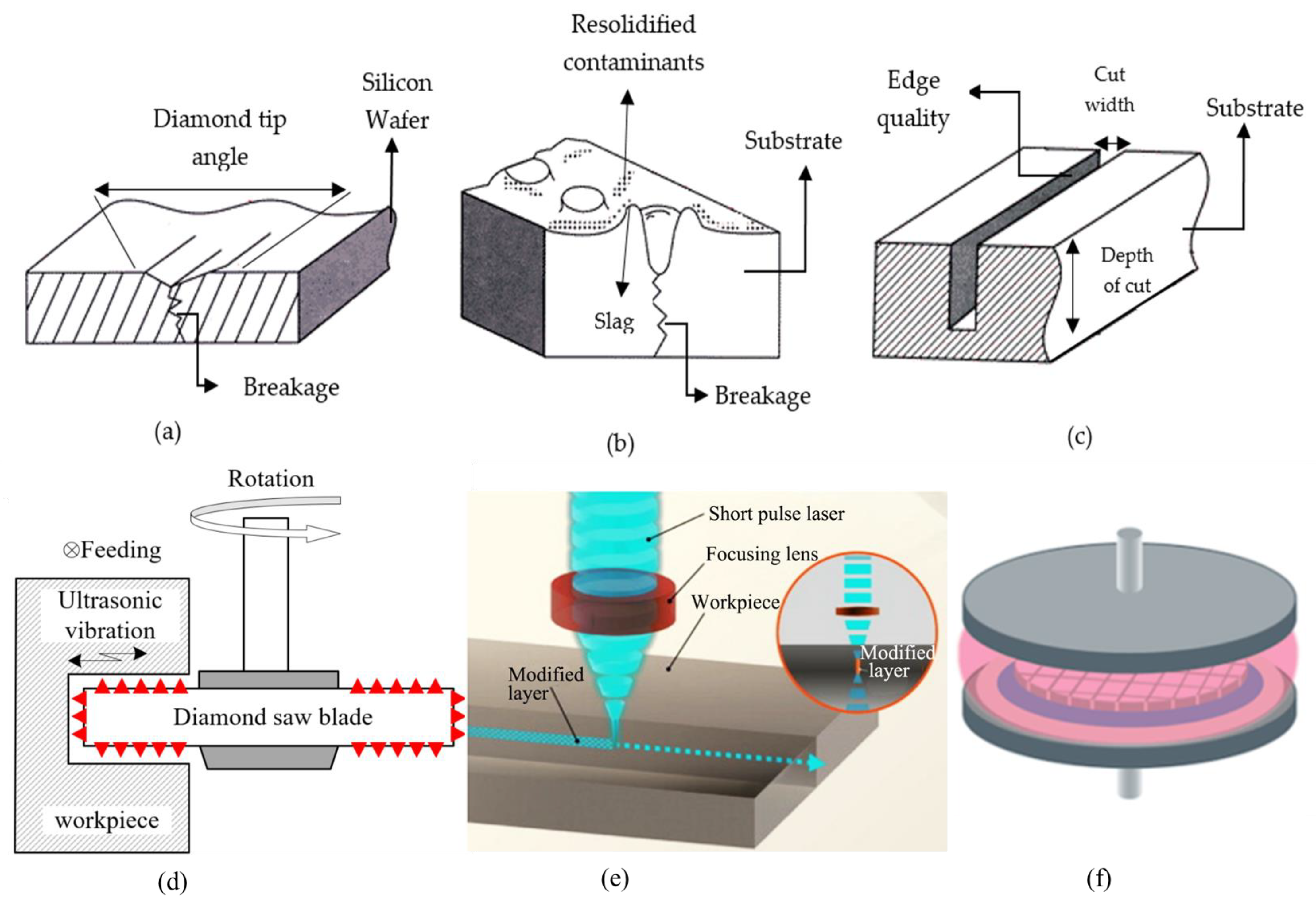
Figure 1.
Die separation techniques: (
a
) diamond scribing; (
b
) laser scribing; (
c
) diamond wheel dicing; (
d
) ultrasonic dicing; (
e
) stealth dicing; (
) plasma dicing.
ICs are mostly less affected by dicing challenges, whereas MEMSs are exposed to atmospheric variables during operation, making them more vulnerable to dicing challenges. A few factors must be taken into consideration in order to fully benefit from dicing blades for MEMS devices. The first challenge is contamination; large particles can stop moving devices, while small particles can disrupt device function. The MEMS structure limits the normal passage of particles that would generally be swept away with water sprayed on it as the wafer is being diced by the dicing blade. The second issue is water pressure damage and dicing forces. Because MEMSs can withstand less stress, water pressure and dicing forces must be kept to a minimum. The third is electrostatic discharge, which occurs when transferring a wafer between stations in a dicing saw and can affect electrostatic components. Some solutions have been proposed for contamination: modify the spray nozzle to change the flow of the nozzle; for water pressure damage, cap the wafer or protect it with a thin film. For forces, use an atomizing nozzle or immerse the wafer in water; for electrostatic discharge, use deionized water and ionizers [10,11][10][11]. Due to the characteristics of the material, the distribution of abrasive grains, the bonding matrix, and cutting parameters of feed speed, depth of cut, and cooling rate, dicing blades may exhibit defects such as delamination, fiber pull out, burrs, microcracks, chipping, nonlinearity, subsurface damage, and uneven cuts. A dicing method capable of meeting profiling needs is required to reduce dicing defects and improve surface characteristics.
Among various dicing techniques, the dicing blade is chosen for this revisewarch—a well-known technique subject to its widespread use for MEMSs and ICs by providing material grooving in addition to slicing, cutting off, cross-sectioning, and slotting [13]. While the use of dicing blades is important, it should not be the only metric to consider. Dicing blade production, dicing parameters (other than machining), and optimization are all viewed as proxies for dicing blade performance evaluation.
2. Preparation Methodology of Dicing Blades
The success of the complex dicing blade production process improves the dicing quality of the cut substrate, as shown in Figure 2 [15][14]. It begins with a ball milling machine mixing powder metals with diamond abrasives in proportion to the component ratio of the dicing blade. After measuring the volume and density of the mixed powder, it is filled in a graphite mold while another metal mold controls the thickness of the powder spread. Before transferring the mixed powder to the graphite mold for sintering in the hot press, the flat scraper removes the redundant powder from the mold. The thinning action on the sintered dicing blade is performed by a double-side lapping machine, and the uniformity of diamond grits is validated by a microscope. DISCO, ADT, Ceiba, Shanghai Sinyang, and UKAM are some of the leading manufacturers of dicing blades in China and across the globe [16][15].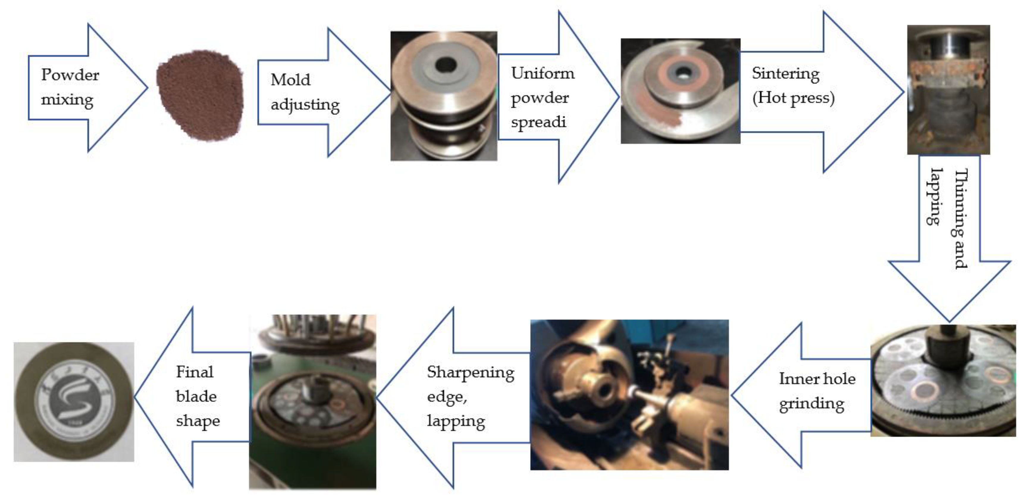
Figure 2. Preparation of dicing blades.
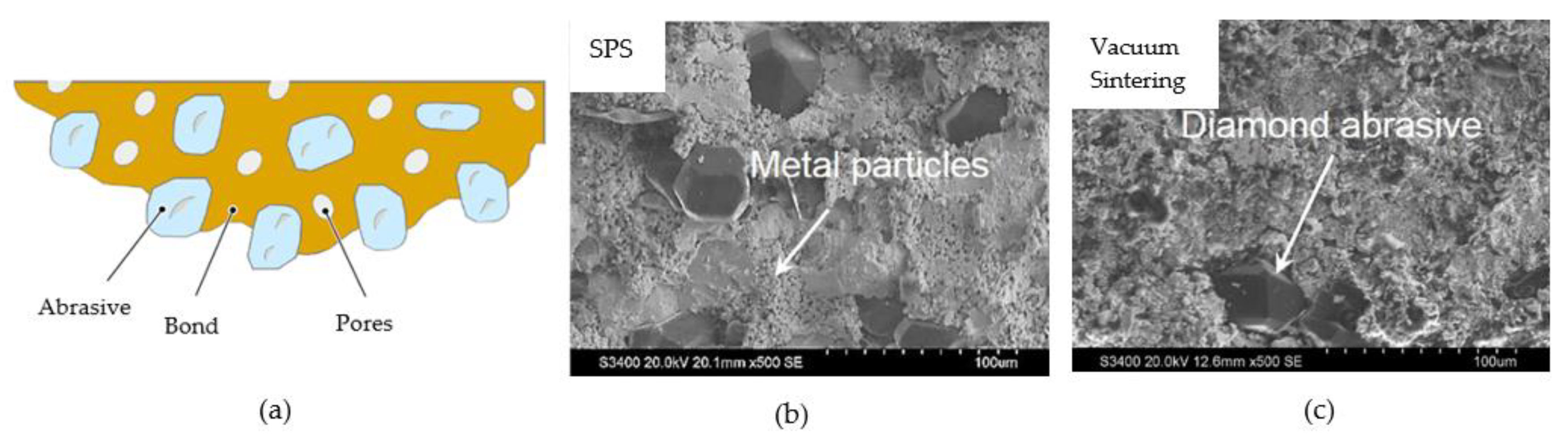
Figure 3. (a) Elements of the abrasive product in dicing blade; SEM micrograph of dicing blade fabricated from (b) SPS; (c) vacuum sintering.
3. Optimization of Dicing Blades
3.1. Through Truing
Truing a diamond dicing blade aids in determining spindle power consumption and mitigates chipping issues [26][25]. The use of trued and dressed blades for circumferential and sidewall grinding on high-hardness substrate materials such as Al2O3, Al2O3-TiC, and SSiC results in high energy consumption. High power consumption was observed for dicing SSiC due to increased sidewall wear in comparison to other materials Al2O3 and Al2O3-TiC. For dicing SiC in the presence of water, a thin polycrystalline diamond blade (PCD) trued by electrical discharge machining (Ed-trued) was used [27][26]. In contrast to excessive chipping with a nontrued blade, an Ed-trued blade produces sharp grooves and chip-free cutting edges, as shown in Figure 4.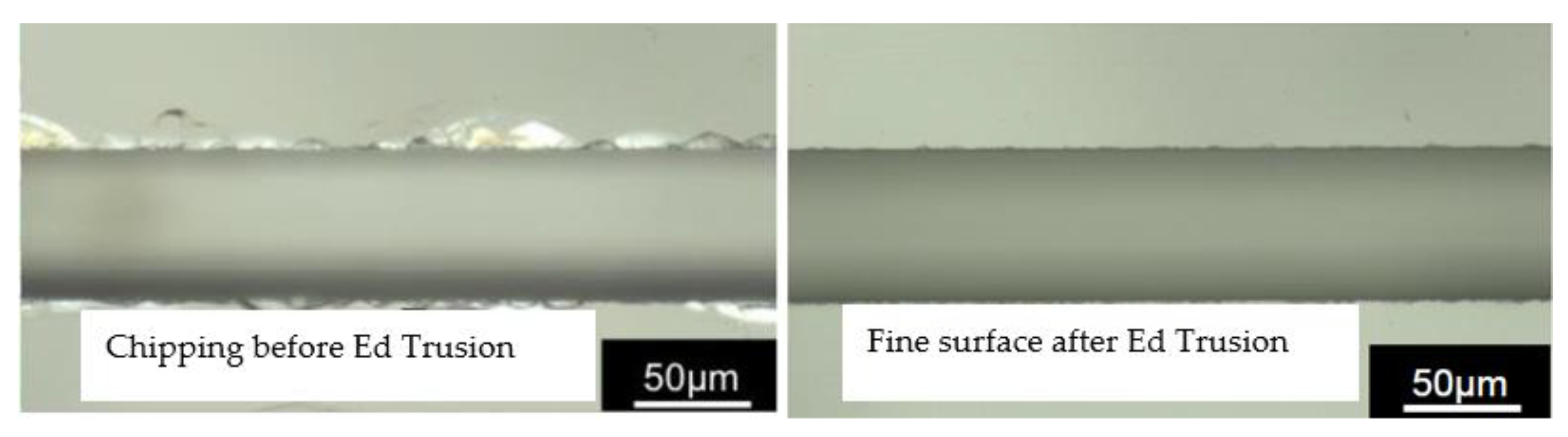
Figure 4. Groove cut with thin PCD blade before and after trusion.
3.2. Through Blade Dressing
During the dicing blade preparation phase, dressing is defined as the process of removing excess bonding material by exposing sharp diamond abrasive grits for a better-quality cut. The use of dressing boards made of silicon carbide produced positive results in terms of capacity and production times, but the dressing process needs to be optimized to produce a dicing wheel topography that is positively correlated with blade profile, geometry, exposure, and cutting force [28,29][27][28]. Continuous laser dressing is possible in dicing machines by combining two capabilities: monitoring sharpness during dicing and performing laser dressing. As a result, researchers attempted to improve the performance of diamond dicing blades through laser dressing, keeping in mind that laser-dressed metal-bonded blades have high sharpness that aids in the processing of difficult-to-cut materials. Dressing on the cutting edge is accomplished by focusing the laser beam on the rotating dicing blade, and the chip space is created on the blade surface through the use of vaporization of the surrounding bonding material [29][28]. Dressing parameters can be adjusted to minimize the thermal influence on diamonds; dressing with a pulse duration of 12 ps provides the best dressing results by filling chip space with diamond abrasive grains to provide a maximum average roughness of Ra = 5 µm for wavelengths of 532 nm and 1064 nm, while less chip space produces a maximum average roughness of Ra = 3.41 µm for 655 ps pulse duration. Moving from laser dressing to continuous laser dressing, where the dicing blade performs the cutting action and the abrasives wear out, laser irradiation helps to remove chips and metal binder from the blade so that the cutting process can be carried out with equal diamond protrusion, as shown in Figure 5. A pulsed laser with a pulse rate of τ = 655 ps and a wavelength of 532 nm can be used to install an on-machine laser dressing facility [30][29]. When compared to traditionally dressed blades, the laser-dressed blade achieved better cutting depth consistency. Investigations into the ability of nickel-bonded diamond blades to produce better results observed that the cutting depth and spindle power consumption stayed constant.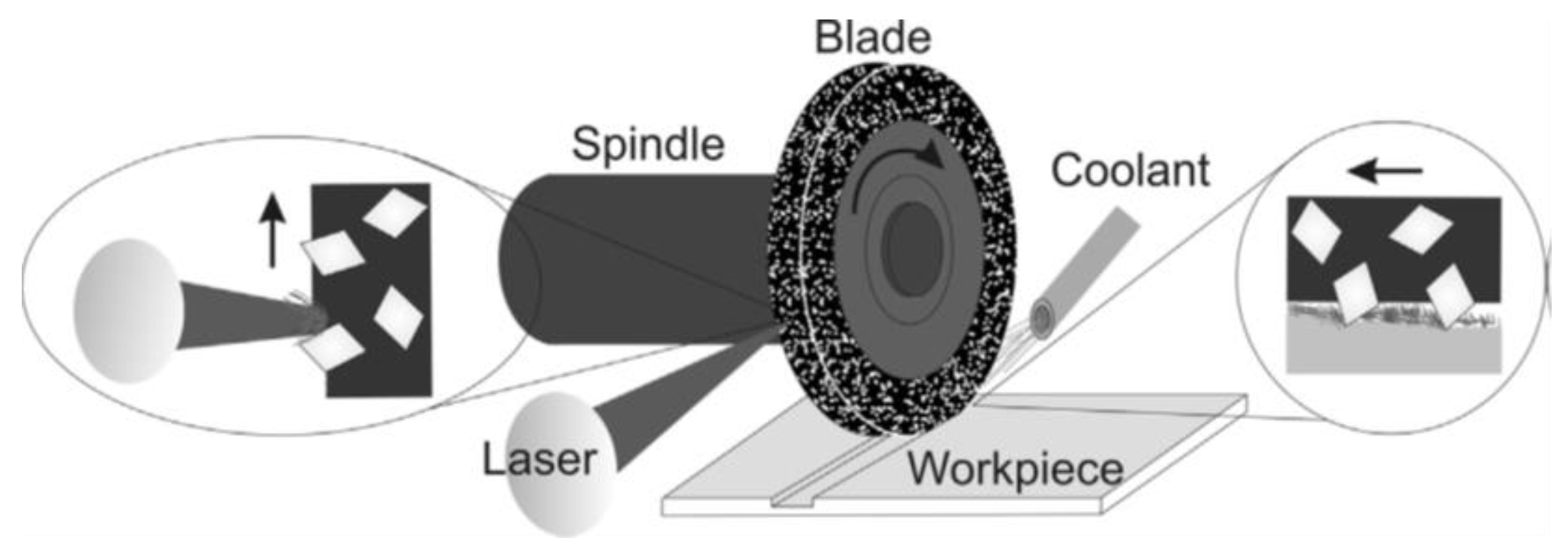
Figure 5. Principle of continuous laser dressing.
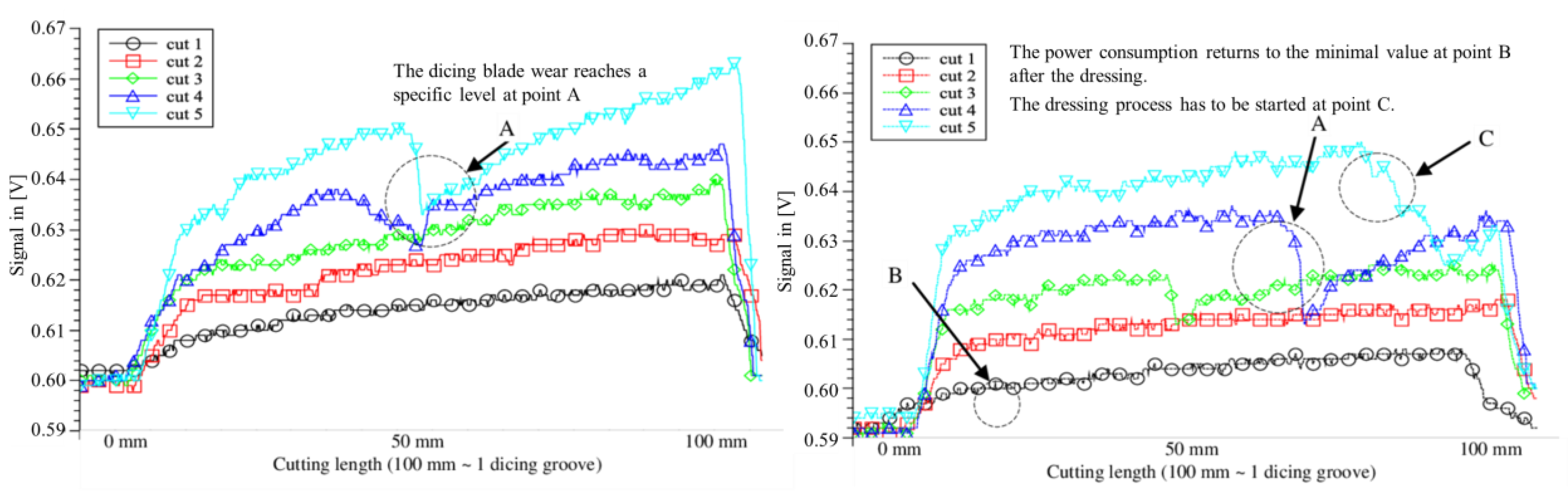
Figure 6. (a) Signal analysis of five cuts before laser dressing; (b) signal analysis of five cuts after laser dressing.
3.3. Through Coating
To improve the performance of dicing blades, coating the cutting tools helps to reduce chipping levels and environmental aspects, such as less cooling water usage and less debris. Thin-film metallic glass (TFMG) coating on Si, SiC, and sapphire blades and patterned sapphire substrates (PSS) reduced chipping area by 23%, 36%, 45%, and 33%, respectively [33][32]. Similarly, titanium-aluminium-nitride (TiAIN) coating on nickel-bond diamond dicing blades improved hardness; the average hardness of the coated and uncoated blades measured was 0.41 Gpa and 0.1 GPa, respectively [34][33]. In addition to coating, BEO (1,4-bis(2-hydroxyethoxy)-2-butyne) can be added to the electrodeposition process of composite coatings during the preparation phase of dicing blades to improve hardness and wear resistance [35][34]. Although adding BEO to the bath helped to reduce chipping levels, coating on composite materials can help researchers find the best quality thresholds. To achieve composite coating on the dicing blades, a suspension and high–low speed interval agitation method was proposed [36][35]. According to the method’s findings, diamond concentration plays an important role in quality, so low grit sizes are recommended. Additionally, the diamond concentration was found to have a direct relationship with the suspended content and an inverse relationship with the stirring speed.3.4. Through Adding Resin
Dicing blades commonly experience breakage; the strength can be increased by immersing the whisker in resin, which acts as a bonding material [37][36]. Apart from helping to strengthen the dicing blades, the light-sensitive resin has an instant solidifying process that uses less pollution and energy. The whisker in the resin greatly influences the mechanical properties of the light-sensitive resin. As a result, tensile strength increases with whisker quantity up to 15% by volume and then begins to decline. When a nonwhisker blade is compared to a whisker-added blade, the former ruptures after the dicing process, whereas the latter shows normal wear throughout. Furthermore, replacing thermosetting resin with photopolymerizable resin in the production of structure-controlled blades such as sandwich-structured, three-layer-structured, and slot-structured dicing blades improves machinability and lowers production costs [38][37]. Photopolymerizable resins with a slot-shaped mask that irradiates the resin with ultraviolet light can be used to create slot-structured blades. Three-layer blades improved in mechanical properties, while the grinding ratio and spindle motor improved as the number of slots increased. However, one disadvantage of using a slotted blade is that the chip size is larger because the workpiece, in this case, contacts more frequently due to the slots.3.5. Through PCD Blade
PCD blades proved advantageous in the ductile-mode dicing process for resolving surface and chipping issues [39][38]. The fabrication of a PCD blade can be accomplished by tangentially irradiating the cutting edge of the rake and flank faces with pulsed laser light. Because of the PCD blade’s high stiffness and hardness, a surface with zero cracks and chipping emerged while undergoing full-cut conditions at high rotational speed; it also managed to cut a thick SiC substrate in one go while avoiding burr formation [40][39]. The developed PCD blade takes advantage of the feature of cutting in a straight line without buckling deformation in cemented carbide; ultrafine grooves with high aspect ratios of 50 were formed, i.e., 20 µm in width and 1 mm in depth, as shown in Figure 7. Due to the presence of distributed edges around abrasive particles, conventional blades are unable to produce such fine grooving; on the other hand, PCD blades have an agglomerated structure of uniform cutting edges for crack-free machining of the substrate.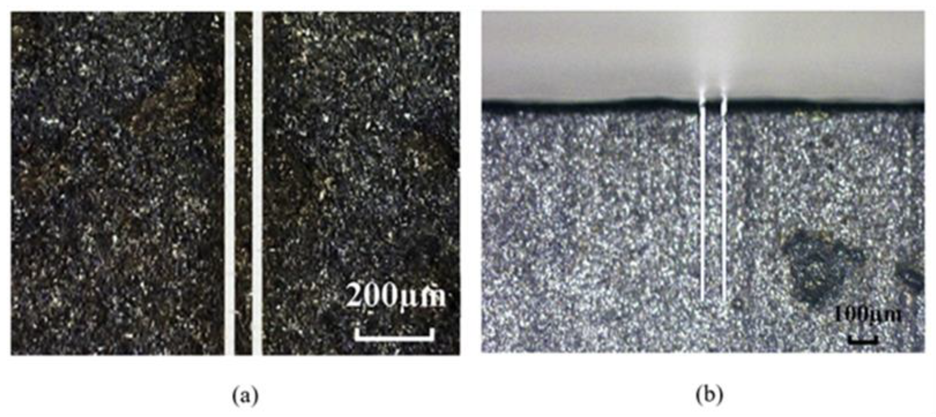
Figure 7. Fine grooving of cemented carbide (groove depth 1 mm, width 20 μm, and length 8 mm): (a) top view of deep grooves; (b) cross-sectional view of deep grooves.
3.6. Through Dual Dicing
Figure 8a depicts the thickness of the spacer between two dicing blades and the diamond protrusion, which determines the size of the structure and helps to prevent excessive chipping and larger angles of the cutting groove sidewall [41][40]. Metal-bonded blades produced 20% less chipping than single dicing by using dual dicing on a stack of materials: anodically bonded silicon carbide, monocrystalline silicon, and borosilicate glass. Furthermore, when compared to a single blade, the outer sidewalls of the cutting groove with a dual blade gave smaller angles of less than one degree, as shown in Figure 8b,c. Although the dual dicing concept can produce microstructures with high aspect ratios, there are limitations regarding the chipping value, which must be less than 10% of the total thickness to prevent rupture. As a result, the impact of dicing blade protrusion requires better understanding. A double-pass sawing method, similar to dual dicing, was proposed to reduce chipping and cracking in silicon wafers laminated with conductive die attach film (DAF) [42][41]. Even though conductive laminated wafers frequently exhibit extreme chipping, the method found that dicing less than 30% of the DAF material resulted in less chipping.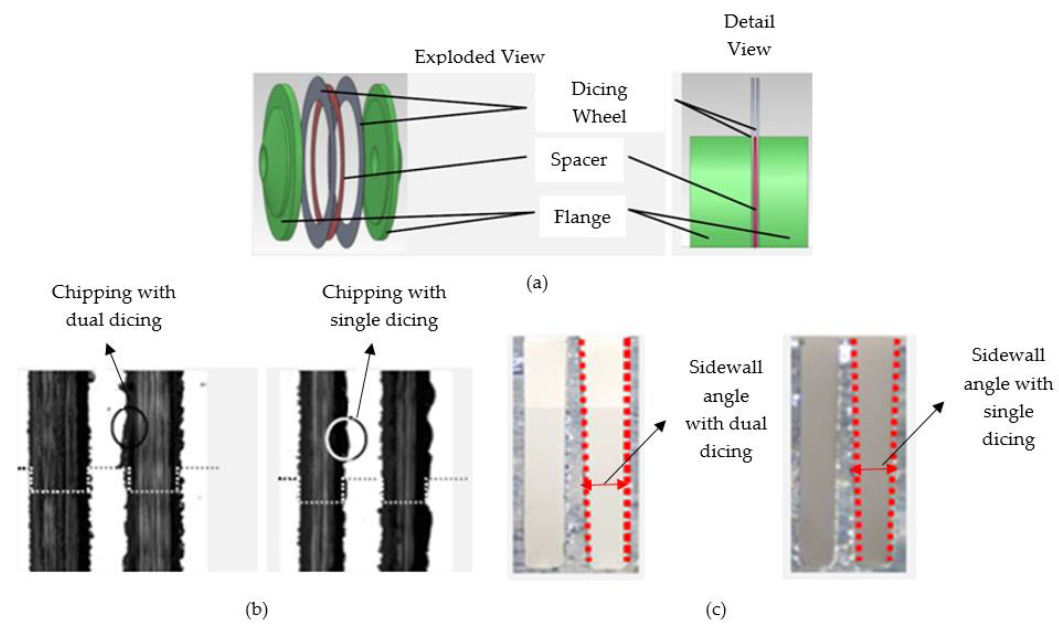
Figure 8. (a) Concept of dual dicing; silicon dicing results comparing single and dual dicing for (b) chipping (c) sidewall angles.
4. Material Removal Mechanism of Dicing Blades
In addition to the primary removal mechanism, a few recommendations in the literature for improving the material removal process provide a clear understanding of the cutting mechanism via dicing blades. The dicing blade material removal process varies based on the morphology of the workpiece. To begin with carbon-fiber-reinforced plastic (CFRP) composites, plastic flow in the local regions of fibers and resins, along with micro breakage, was identified as the primary material removal mechanism. Furthermore, macroscopic and microscopic simulations are suggested for gaining a better understanding of the CFRP composite cutting mechanism [48][42]. Likewise, plastic flow is responsible for cutting in the grinding of brittle materials [58][43]. For composite materials, the material removal process changes as the fiber orientations change, as shown in Figure 9b–f. If the dicing direction is parallel to the fiber orientation, the scratching action takes advantage of improper fiber embedding in the matrix [48][42]. A perpendicular dicing direction to fiber orientation, on the other hand, proceeds the cutting action with a diamond grit tip owing to the small cutting depth and proper fixation of carbon fibers in the matrix, resulting in a smooth surface finish. Dicing at an angle causes visible fiber breakage due to delicate support and extreme cutting force applied by diamond grits. For the cutting process with silicon, three material removal steps are responsible: rubbing, plastic deformation, and cracking, whereas for alumina, intergranular and transgranular mechanisms play a role [45][44].
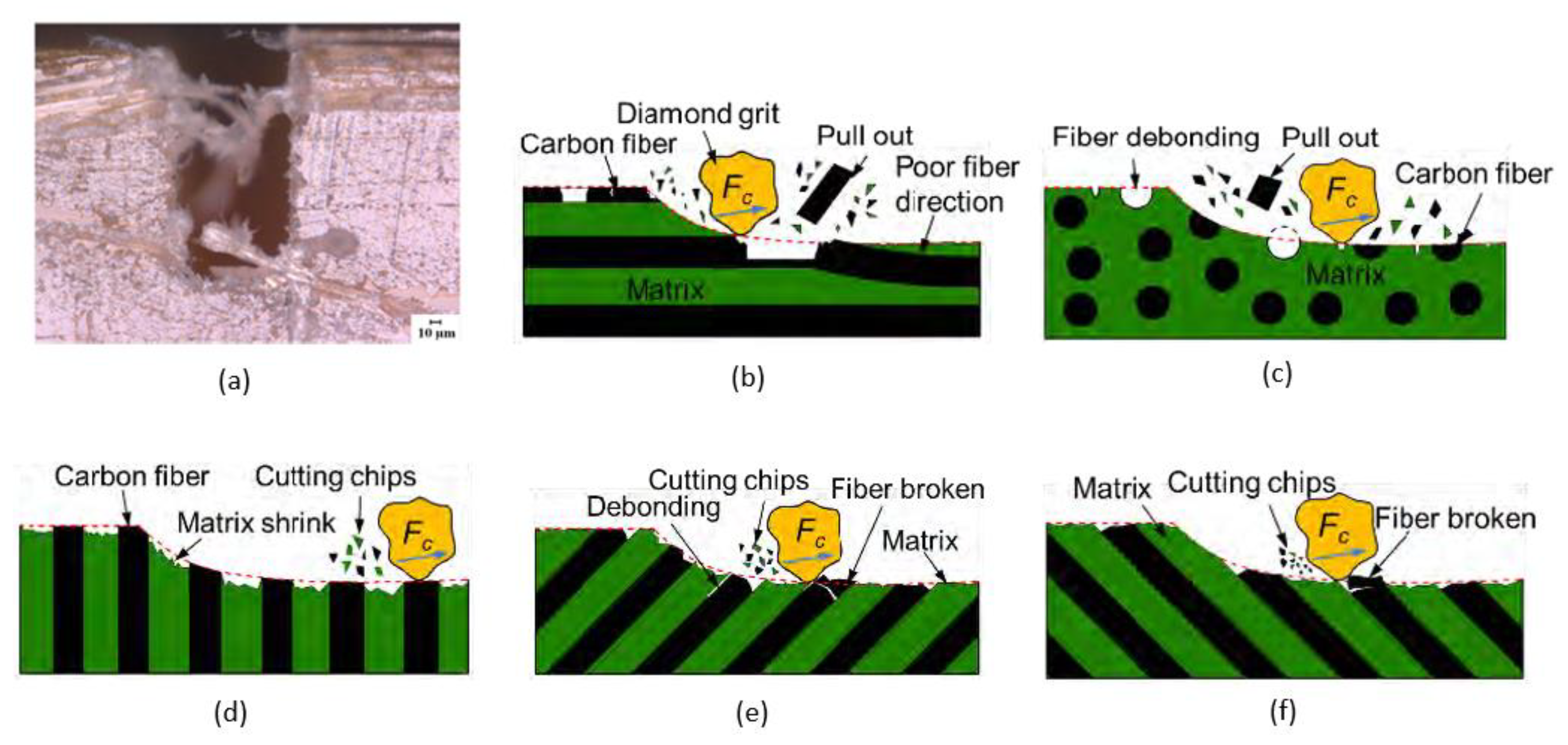
Figure 9. Surface morphology of AFRP composites after dicing: (a) morphology of the groove side; (b) schematic diagram of dicing mechanism with different fiber orientations for CFRP composites; (c) dicing direction parallel to fiber orientation; (d) dicing direction perpendicular to fiber orientation; (e) dicing direction with an angle of 45° to fiber orientation; (f) dicing direction with an angle of 135° to fiber orientation.
Numerical simulations for sapphire substrates revealed that the plowing action caused by the grinding particles and sinter was a significant factor in material removal. Figure 9a depicts the side topography of the cutting groove in aramid fiber-reinforced plastic (AFRP) composites; due to the higher toughness of aramid fibers, peeling instead of cutting results in a small number of burrs on the cutting groove edges [52][45]. The cutting mechanism of AFRP composites can be improved by using abrasive particles with cutting edges smaller than the diameter of the aramid fibers, which reduces damages caused by tool size and corresponding cutting speed.
References
- Von Witzendorff, P.; Stompe, M.; Suttmann, O.; Rissing, L.; Overmeyer, L. Investigation of the cutting performance of laser dressed metal bonded diamond blades. Intl. Cong. App.L. Elect.Opt. 2013, 2013, 840–845.
- Deng, H.; Xu, Z. Laser-dressing topography and quality of resin-bonded diamond grinding wheels. Opt. Lasers Eng. 2021, 136, 106322.
- Han, W.; Kunieda, M. Precision electrochemical machining of tungsten micro-rods using wire electrochemical turning method. Int. J. Adv. Manuf. Technol. 2020, 111, 295–307.
- Miao, X.; Qiang, Z.; Wu, M.; Song, L.; Ye, F. The optimal cutting times of multipass abrasive water jet cutting. Int. J. Adv. Manuf. Technol. 2018, 97, 1779–1786.
- Mizuno, M.; Iyama, T.; Zhang, B. Analysis of the sawing process with abrasive circular saw blades. J. Manuf. Sci. Technol. 2008, 130.
- Efrat, U. Optimizing the wafer dicing process. In Proceedings of the 15th IEEE/CHMT International Electronic Manufacturing Technology Symposium, Santa Clara, CA, USA, 4–6 October 1993.
- Principles of Dicing. Available online: https://www.inseto.co.uk (accessed on 13 November 2022).
- 061127-Dicing Saw (Dicing Saw, Blade) PPT. Available online: https://wenku.baidu.com (accessed on 18 May 2022).
- Shen, J.; Zhu, X.; Chen, J.; Tao, P.; Wu, X. Investigation on the Edge Chipping in Ultrasonic Assisted Sawing of Monocrystalline Silicon. Micromachines 2019, 10, 616.
- Sullivan, S. Dicing of MEMS Devices. In Handbook of Silicon Based MEMS Materials and Technologies, 1st ed.; Elsevier: Oxford, UK, 2010; pp. 601–606.
- Martin, D.; Sullivan, S. Dicing of MEMS Devices. In Handbook of Silicon Based MEMS Materials and Technologies, 2nd ed.; Elsevier: Oxford, UK, 2015; pp. 671–677.
- Plasma Dicing 101: The Basics. Available online: https://www.kla.com (accessed on 13 November 2022).
- Precision Processing Tools. Available online: https://www.disco.co.jp/eg/support/term/doc/PrecisionProcessingTools.pdf. (accessed on 13 May 2022).
- Yuan, Z.; Feng, S.; Wu, T. Preparation and characterization of ultra-thin dicing blades with different bonding properties. Int. J. Adv. Manuf. Technol. 2022, 119, 1–16.
- Yuan, Z.; Cheng, K.; Zhang, Y.; Hu, J.; Zheng, P. Investigation on the fabrication of dicing blades with different sintering methods for machining hard-brittle material wafers. Proc. Inst. Mech. Eng. Pt. B J. Eng. Manuf. 2019, 233, 1781–1793.
- Selecting Right Diamond Dicing Blade for Your Application. Available online: https://www.ukam.com (accessed on 13 May 2022).
- Creating Man-Made Diamonds. Available online: https://d.neadiamonds.com (accessed on 2 February 2023).
- Lab-Grown Diamond Production Methods. Available online: https://www.gemsociety.org (accessed on 2 February 2023).
- Wang, J.; Zhao, Q.; Zhang, C.; Guo, B.; Yuan, J. Arc envelope grinding of sapphire steep aspheric surface with sic-reinforced resin-bonded diamond wheel. Int. J. Prec. Eng. Manuf. G. Technol. 2021, 8, 1083–1094.
- Monteverde, F. Hot pressing of hafnium diboride aided by different sinter additives. JMatS 2008, 43, 1002–1007.
- Yu, Z.; Zhao, P.; Hu, F. Study on UV Curing Behavior and Properties of ES/CEP Resin. Cai. Dao./Mat. Rev. 2018, 32, 263–267.
- Gild, J.; Kaufmann, K.; Vecchio, K.; Luo, J. Reactive flash spark plasma sintering of high-entropy ultrahigh temperature ceramics. Scripta Mater. 2019, 170, 106–110.
- Song, S.-X.; Wang, Z.; Shi, G.-P. Heating mechanism of spark plasma sintering. Ceram. Int. 2013, 39, 1393–1396.
- Cho, H.J.; Yan, D.; Tam, J.; Erb, U. Effects of diamond particle size on the formation of copper matrix and the thermal transport properties in electrodeposited copper-diamond composite materials. JAllC 2019, 791, 1128–1137.
- Stompe, M.; Cvetkovic, S.; Taptimthong, P.; Rissing, L. Ultra-precision Dicing Process Separation: Effect of Circumferential and Sidewall Grinding. In Proceedings of the 12th euspen International Conference, Stockholm, Sweden, 4–8 June 2012.
- Watanabe, K.; Yanagida, D.; Minami, H.; Izumi, Y. Electrical discharge truing of a PCD blade tool on a dicing machine. Procedia CIRP 2020, 95, 494–498.
- Shi, K.W.; Yow, K.; Khoo, R. Developments of blade dressing technique using SiC board for C90 low-k wafer sawing. In Proceedings of the 13th Electronics Packaging Technology Conference, Singapore, 7–9 December 2011.
- Von Witzendorff, P.; Moalem, A.; Kling, R.; Overmeyer, L. Laser dressing of metal bonded diamond blades for cutting of hard brittle materials. JLasA 2012, 24, 022002.
- Von Witzendorff, P.; Stompe, M.; Moalem, A.; Cvetkovic, S.; Suttmann, O.; Overmeyer, L.; Rissing, L. Dicing of hard and brittle materials with on-machine laser-dressed metal-bonded diamond blades. Prec. Eng. 2014, 38, 162–167.
- Stompe, M.; Witzendorff, P.; Cvetkovic, S.; Moalem, A.; Stute, U.; Rissing, L. Concept for performance-enhancement of ultra-precision dicing for bulk hard and brittle materials in micro applications by laser dressing. MiEng 2012, 98, 544–547.
- Stompe, M.; Cvetkovic, S.; Taptimthong, P.; Rissing, L. Dressing Criteria for Inline Laser Dressing of Metal-bonded Dicing Blades. In Proceedings of the 12th euspen International Conference, Stockholm, Sweden, 4–8 June 2012.
- Chu, J.; Lai, B.-Z.; Yiu, P.; Shen, Y.-L.; Chang, C.-W. Metallic glass coating for improving diamond dicing performance. Sci. Rep. 2020, 10, 1–10.
- Hishamuddin, M.I.; Nayan, N. Reverse Engineering of Dicing Blade to Prolong its Lifetime. Evol. Elect. Electr. Eng. 2020, 1, 161–166.
- Deng, J.; Zhang, J.; Tu, Y.; Yang, P.; An, M.; Wang, P. Effect of BEO in the electrodeposition process of Ni/diamond composite coatings for preparation of ultra-thin dicing blades: Experiments and theoretical calculations. Ceram. Int. 2018, 44, 16828–16836.
- Zhu, X.; Wang, Y.; Liu, J.; Wang, Z.; Dong, F. Research of diamond concentration in dicing blade effect by electroplating parameter. In Proceedings of the International Conference on Advanced Composite Materials and Manufacturing Engineering, Yunnan, China, 22–23 June 2019.
- Peng, W.; Xu, X.; Zhang, L. Improvement of a dicing blade using a whisker direction-controlled by an electric field. J. Mater. Process. Technol. 2002, 129, 377–379.
- Lee, S.; Tani, Y.; Enomoto, T.; Sato, H. Development of a dicing blade with photopolymerizable resins for improving machinability. CIRP Ann. 2005, 54, 293–296.
- Fujita, T.; Izumi, Y.; Watanabe, J. Ultra-fine grooving technology with high aspect ratio for cemented carbide by PCD (poly-crystalline diamond) blade. Prec. Eng. 2019, 55, 381–389.
- Fujita, T.; Izumi, Y.; Watanabe, J. Ultrafine ductile-mode dicing technology for SiC substrate with metal film using PCD blade. J. Adv. Mech Des. Syst. Manuf. 2019, 13, 1–14.
- Stompe, M.; Cvetkovic, S.; Rissing, L. Dicing concept for mechanical structured materials and multi- layer-specimens. In Proceedings of the 13th euspen International Conference, Berlin, Germany, 27–31 May 2013.
- Jiun, H.; Ahmad, I.; Jalar, A.; Omar, G. Effect of Laminated Wafer Toward Dicing Process and Alternative Double Pass Sawing Method to Reduce Chipping. Electr. Pack. Manuf. IEEE Trans. 2006, 29, 17–24.
- Yuan, Z.; Hu, J.; Wen, Q.; Cheng, K.; Zheng, P. Investigation on an Innovative Method for High-Speed Low-Damage Micro-Cutting of CFRP Composites with Diamond Dicing Blades. Materials 2018, 11, 1974.
- Bifano, T.G.; Dow, T.A.; Scattergood, R.O. Ductile-regime grinding: A new technology for machining brittle materials. J. Manuf. Sci. Technol. 1991, 113, 184–189.
- Araujo, L.; Foschini, C.; Jasinevícius, R.; Fortulan, C. Precision dicing of hard materials with abrasive blade. Int. J. Adv. Manuf. Technol. 2016, 86, 2885–2894.
- Wen, Q.; Hu, J.; Yuan, Z. Sub-Fiber Scale Precision Dicing of Aramid Fiber-Reinforced Plastic Composites. Mac 2022, 10, 334.
More