Your browser does not fully support modern features. Please upgrade for a smoother experience.
Please note this is a comparison between Version 1 by Muhammad Tawalbeh and Version 3 by Rita Xu.
Proton exchange membrane fuel cells (PEMFCs) operate by converting the chemical energy in a fuel into electrical energy. The most crucial parameters in the operation process are the temperature, pressure, relative humidity, and air stoichiometry ratio. The classical structure of a PEMFC consists of a proton exchange membrane, anode electrode, cathode electrode, catalyst layers (CLs), microporous layer (MPLs), gas diffusion layers (GDLs), two bipolar plates (BPs), and gas flow channels (GFCs). The mechanical behavior and the conductivity of the protons are highly dependent on the structure of the MEAs.
- PEM fuel cells
- fuels
- biomass
- proton conduction membranes
1. Introduction
Over the past few decades, the enormous energy generation from fossil fuels and dispersion of industrialization have increased greenhouse gas (GHG) emissions, mainly carbon dioxide, which is the major contributor to global warming and climate change [1][2][3][1,2,3]. Hence, cleaner and more efficient energy sources with low pollutant emissions and noise levels are required [4]. Among the various renewable energy sources, fuel cells are a promising alternative for stationary power stations, transportation, portable electrSonics, backup power systems, and other applications [5][6][5,6].
Fuel cells are electrochemical devices that convert the chemical energy stored in fuels directly to electrical power. There are various types of fuel cells, such as proton exchange membrane fuel cells (PEMFCs), solid oxide fuel cells (SOFCs), molten carbonate fuel cells (MCFCs), alkaline fuel cells (AFCs), and phosphoric acid fuel cells (PAFCs) [7][8][9][7,8,9]. In particular, PEMFCs have recently attracted the attention of the power generation market around the world, due to many advantages that include a high power density, high efficiency, low operating temperature, zero-emissions (depending on the fuel used) [10], a solid structure, and being environmentally friendly [11]. Additional advantages include their rapid start-up and silent operation [12][13][12,13]. The by-products of PEMFC are water and heat if a hydrogen fuel is used. The PEMFC components consist of bipolar plates (BPs) and storage tanks, in addition to catalyst layers (CLs), electrodes, membrane, gas diffusion layers (GDLs), and microporous layers (MPLs), which are called the membrane electrode assembly (MEA) [11]. The most common CLs in PEMFCs are platinum (Pt)-based [14]. Catalysts based on platinum, palladium, and gold have been utilized. Among them, Pt has exhibited a remarkable performance over other metals regarding synergized electrochemical activity, especially oxidation reactions at the anode and oxygen reduction reactions (ORRs) at the cathode in low-temperature PEMFCs [15]. Despite this superior performance, the high-cost factor can be minimized with an optimum size of the platinum catalyst. The electrolyte, in most cases, is made of Nafion material, which has good mechanical properties and provides a high proton conductivity at temperatures around 80 °C [16].
There are many types of fuels used to operate PEMFC, such as hydrogen, hydrocarbons in general, and alcohols (e.g., ethanol and methanol). Hydrogen fuel is considered a promising fuel to operate PEMFC, with water as a byproduct only at a high power density. Usually, around 95% of hydrogen fuel is produced from fossil fuels; however, there are green production methods, such as water electrolysis and gasification of biomass [17]. Even though hydrogen fuel suffers from a high cost for transferring, compressing, and storage, it possesses some features such as burning without toxic emissions and having a gravimetric heating value much higher than hydrocarbon fuel (by three times) [18]. Furthermore, hydrogen fuel is stored/transported efficiently in a tank under a very high compression pressure, as it is ultra-light gas with substantial volume occupation, which can be reduced by applying high-pressure conditions. The PEMFC operates at a temperature range from 60 to 85 °C for low-temperature PEMFC (LT-PEMFC), on the other hand, the temperature operation range varies from 120 to 140 °C in the case of high-temperature PEMFC (HT-PEMFC), with an average power capacity of ≤120 kW and electrical efficiency of 50–60% [19]. Nevertheless, PEMFC technology still faces several technical and economic challenges, which are related to the cost of catalysts, operating temperature conditions, durability/stability [20], the infrastructure of membrane electrode assembly (MEA) corrosion [21], and water management problems [22][23][24][22,23,24].
The introduction of the infrastructure of hydrogen stations (pipelines, liquefaction/storage facilities, and compressors) requires a robust control system and an optimized design of the fuel cell stack for efficient operation [25]. Degradation affects the expensive membrane and cathode electrode structures. The high cost of PEMFC occurs due to the high price of the platinum and membrane materials [26]. Flooding problems occur because of the reduction reaction at the cathode, and this process leads to water generation in the liquid form at the cathode [27].
The sustainable development of societies should be governed by sustainable energy sources that do not cause environmental pollution. Recently, there have been many efforts aimed at finding a sustainable solution for producing various fuels and reducing carbon footprints. Catalytic hydrogenation of carbon dioxide appears to offer an opportunity and a challenge at the same time. It is directly impacted by the development of novel catalysts and environmentally friendly approaches. Fuel cell systems are believed to play a key role in achieving sustainability, especially when they operate using hydrogen or other sustainable fuels [28][29][28,29]. Fuel cells are receiving attention because they possess a high theoretical efficiency [30], are environmentally friendly [31], and have zero to low emissions (depending on the fuel) [32].
2. PEMFC Operation
The basic operating system of the PEMFC relies on the main components of it is structure, such as the anode electrode, cathode electrode, CLs, proton exchange membrane, GDLs, and BPs. The PEMFC system in Figure 1 is supplied with hydrogen fuel at the anode layer [33]. The protons and electrons are formed due to the electro-oxidation reaction of hydrogen at the CL. The generated electrons move through an external circuit to produce a DC electrical current, whereas the protons reach the cathode side by traveling through the electrolyte, which is a proton conductive polymer (e.g., Nafion) [33]. The PEMFC system is provided with oxygen at the cathode layer; thus, the reaction of hydrogen protons and electrons with oxygen generates water and heat [34].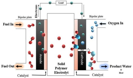
2.1. The Fuel Cell Operation Pressure
The fuel cell pressure has a proportional relationship with the partial pressure of hydrogen and oxygen in the flow channels of the anode and cathode compartments. When the fuel cell pressure increases, the performance of PEMFCs increases at low current densities, as reported by Askaripour in Figure 2 [35]. Askaripour showed that the PEMFC performance improved at 0.4 A/cm2 of current density, with different inlet cell pressure values. At current densities larger than 0.4 A/cm2, the performance and the open-circuit voltage decrease, and the cathode activation, Ohmic, and concentration losses also increase. Li et al. [36] performed a comparative analysis on thick/thin MEAs for high FCs performances. The low ohmic resistance, low ohmic polarization, and ease of hydration at low humidity offered by thin MEAs/membranes improved the current density, the cathode catalyst O2 reduction activity, and localized O2 transport. The maximum performance of the thin MEA was reported with a 50 cm2 PEM fuel cell and a peak current density of 2.51 A/cm2, at 0.65 V operation under 50% RH (at the cathode and at the anode) and a counter-cross flow pattern. In another study, the enhancement of power density was investigated with a variation in temperature/pressure, RH of anode/cathode, and proton conductivity of the porous gas diffusion electrode (GDE), with the support of the vector machine (SVM) approach [37]. At an optimized temperature of 86.2 K and 3.44 atm fuel cell pressure, a peak power density of 870 mW/cm2 and conductivity of 997.7 S/m were reported at a RH of 50% and 64.4% for anode and cathode, respectively. It should be noted in this context that this temperature (86.2 K) is not practical.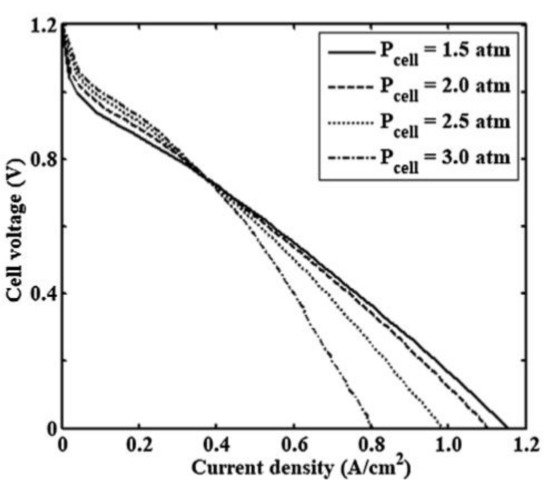
Figure 2.
The effect of different cell operating pressures on the polarization curve (Reprinted with permission from Ref. [35], license No. 5353090032287).
2.2. The Fuel Cell Operation Temperature
The fuel cell operating temperature is considered a crucial parameter in a fuel cell operating system. The operating temperature influences the membrane conductivity, current density, synthesis of input gas streams, and water vapor pressure. The molar fraction of hydrogen and oxygen relies on the temperature and the inlet pressure. The cell operating temperature affects the kinetics of PEMFC; when the temperature increases, the current density (reaction rate) increases [38]. The operating temperature must be selected in a suitable range, to obtain a constant electrochemical reaction rate, and to avoid corrosion/degradation of the PEMFC materials. At high temperatures, the membrane dehydrates or decomposes (depending on the material); thus, the cell voltage decreases, and hence, the performance and efficiency of the fuel cell will eventually be reduced. The optimum temperature range for LT-PEMFC may be about 65–85 °C and for HT-PEMFC about 120–140 °C [39]. Badduri et al. [40] reported that the performance of a PEMFC was improved when the temperature increased from 45 °C to 75 °C at 100% RH, 1.5 bar of inlet operating pressure, and the back pressure equaled ambient pressure. On the other hand, when the temperature was increased up to 85 °C, the performance of the PEMFC was impacted negatively, because of the membrane dehydration; thus, the Ohmic losses increased, which in turn reduced the ionic conductivity of the membrane. The obtained optimum conditions were a 0.41 W/cm2 power density at 0.69 A/cm2 of current density, at an optimal operating temperature of 75 °C, as shown in Figure 3 [40]. Xia et al. [41] examined the temperature effect on the polarization curve of HT-PEMFC at a temperature range from 101 to 180 °C. The highest ionic conductivity of 7.8 S/m occurred at 160 °C. They noted a reduction in power density when the temperature varied from 160 to 180 °C, at a current density of 1.05 A/cm2. The reduction happened because of the rising water content. The optimum operating temperature was in the range of 160–180 °C, the HT-PEMFC showed a high performance, with high power densities. Wannek et al. [42] carried out a detailed analysis of the HT-PEMFC system over a temperature range of 140–200 °C and measured current/power density. With the rise in operating temperatures, novel ABPBI membranes showed a decrease in resistance, which ultimately enhanced the power density up to 250 mW/cm2, as shown in Figure 4.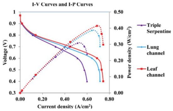
Figure 3.
The performance of three-channel designs at the optimum temperature of 75 °C(Reprinted with permission from Ref. [40], license No. 5353090612869).
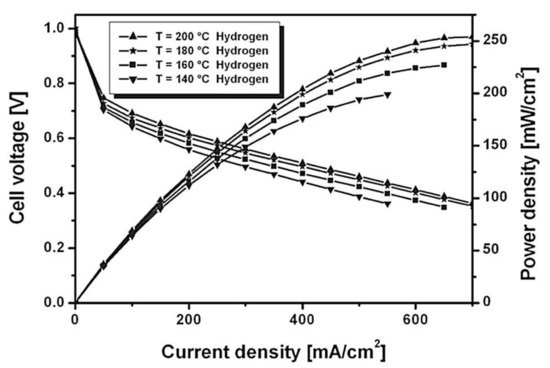
Figure 4. The effect of different operating temperatures on the performance of a H2-based HT-PEMFC at ambient pressure [42].
2.3. Relative Humidity
The relative humidity (RH) of a cell affects the membrane resistance. Whenever the humidity increases, the Ohmic losses decreases, due to a reduction in membrane resistance and the enhancement in proton conduction paths, by virtue of the available water content. A dehydrated membrane, on the other hand, restricts the movement of the protons because of a lack of water content (necessary for proton hopping); thus, the current density drops. An optimal relative humidity improves the cell voltage, increases the power density, and eventually the fuel cell performance. Li et al. [36] conducted an experimental study on PEMFCs with thin MEA under a low humidity at the anode of 50% and anhydrous conditions at the cathode. Then, under fuel cell operating conditions of 0.65 V, 0% relative humidity at the cathode, 50% relative humidity at the anode, and thin MEA, the average current density obtained was 2.51 A/cm2. As mentioned earlier, Peng et al. [37] reported that the operation conditions of RH at the anode were 50%, RH at the cathode was 64.4%, with an optimum operating temperature of 86.2 K, 3.44 atm of cell operating pressure, 50% porosity of the gas diffusion electrode (GDE), and 997.7 S/m conductivity of the GDE generated 870 mW/cm2 of power density of PEMFC. In this context, it should be noted that the temperature of 86.2 K reported in the previous work (Peng et al.) is not practical. Peng et al. compared their results to Cheng et al. [43], where the pressure and temperature were 3 atm and 80 °C (353 K), respectively. Toghyani et al. [38] examined the effect of a fuel recirculation system that contained a compressor and an electrochemical pump in a PEMFC stack operating at temperatures 60–80 °C. An electrochemical pump is a device used to compress hydrogen gas. They noticed that when the relative humidity varied from 20 to 100%, the recirculation ratio increased from 1.18 to 1.5 and the hydrogen stoichiometric ratio was raised from 1.64 to 1.82. The electrochemical pump was assessed and compared with the ejector. Figure 5 shows the PEMFC stack voltage as a function of RH. The results revealed that the voltage was reduced from 17.99 to 17.03 mV with the increase in RH, accompanied by a decrease in power consumption (for the electrochemical pump) from 0.535 to 0.506 W.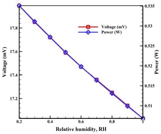
Figure 5.
Effect of anodic relative humidity of PEMFC on the voltage and power of the pump (Reprinted with permission from Ref. [38], license No. 5353100068143).
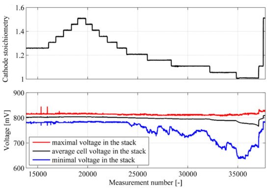
2.4. Air Stoichiometry Ratio
The air stoichiometry ratio has a direct effect on the abundance of oxygen and the hydration level of the membrane [44]. Air stoichiometry ratio is defined as the ratio of injected oxygen to the oxygen required by stoichiometry (chemical reaction). At a low stoichiometric ratio of airflow, the rate of water removal is reduced thereafter, and the amount of oxygen that arrives at the membrane decreases; however, the humidity of the membrane increases [45]. Hence, the membrane resistance is also reduced. The availability of more oxygen in the air enhances the kinetics at the cathode. When the airflow ratio exceeds an optimal value of air stoichiometry ratio at a low current density, the electrical resistance has a slight effect on the fuel cell voltage [46]. At a high value of current density and a high value of the airflow rate, a significant effect on the fuel cell voltage is observed, because increasing the oxygen content enhances the formation of water at the cathode. To enhance the performance of a PEMFC, a high value of current density and an optimal rate of air stoichiometry should be met [47]. This is because of the water accumulation at the cathode, which imposes mass transfer limitations, preventing more oxygen from reaching the catalyst’s surface [48]. Qu et al. [49] mentioned that changing the stoichiometry air ratio affected the cell voltage and the current density. The study indicated that the extent of air dilution/starvation at the end of the flow field channel depended on many factors, including the air stoichiometric flow ratio. The study also showed that the downstream oxygen content in the flow field was depleted progressively during the load change. Under air starvation conditions, a cell voltage undershoot was observed, which could be enhanced by increasing the airflow rates. Polak et al. [50] examined changing the oxygen stoichiometry ratio from 1.25 to 1.5, and their findings showed that the cell voltage at a 1.5 cathode stoichiometry ratio was higher than the cell voltage at 1.25, by 3 mV, due to the increase in the oxygen flow rate. Below ratios of 1.2 of cathode stoichiometry rate, the researchers noticed a critical variation of the cell voltage, because of imperfect cathode ventilation, due to the flooding in the cell, as seen in Figure 6. Kim et al. [51] reported that the voltage drops increased when the air stoichiometry rate decreased below 2.0, because of the low rate of water removal and a lower concentration of oxygen, high mass transport resistance occurred.