Your browser does not fully support modern features. Please upgrade for a smoother experience.
Please note this is a comparison between Version 2 by Rita Xu and Version 1 by Ge Mu.
Multi-color light-emitting diodes (LEDs) with various advantages of color tunability, self-luminescence, wide viewing angles, high color contrast, low power consumption, and flexibility provide a wide range of applications including full-color display, augmented reality/virtual reality technology, and wearable healthcare systems.
- multi-color LED
- OLED
- QLED
- CQD–organic hybrid LED
1. Introduction
Light-emitting diodes (LEDs) are semiconductor optoelectronic devices that emit light when electrons and holes recombine under applied voltage [1,2,3,4][1][2][3][4]. Multi-color LEDs with various advantages of color tunability, self-luminescence, wide viewing angles, high color contrast, and low power consumption are considered as the new-generation full-color displays used in televisions, laptops, mobile phones, and augmented reality/virtual reality technology [3]. In addition, the excellent flexibility and thin thickness of multi-color LEDs provide a wider range of applications in emerging optoelectronic devices including folding full-color displays, smartwatches, and wearable healthcare systems [5]. Furthermore, multi-color LED integration with the sensor is a promising and innovative way to visualize the electronic output signal of sensors to different visible colors, which has great application prospects in various applications such as real-time electrocardiogram monitors and electronic skin sensors [6,7][6][7].
Organic LEDs (OLEDs) are a type of LED in which the emissive electroluminescent layer is a film of the organic compound [7,8,9,10,11,12][7][8][9][10][11][12]. In 1950, French chemist André Bernanost for the first time discovered the electroluminescent properties of organic compounds; since then, tremendous progress has been made in the development of OLED technology [4,13,14][4][13][14]. Up to now, OLEDs have been mass-produced and commercialized, and successfully applied in either rigid or flexible OLED displays and excellent solid-state lighting [15,16][15][16]. Due to the mature application foundation of monochrome OLEDs for years, multi-color OLEDs with various lateral/vertical integration configurations have been fairly widely researched [17,18,19,20][17][18][19][20].
In recent years, colloidal quantum dots (CQDs) have been considered to be promising visible emitter materials to replace organic luminescent materials due to their inherent luminescent properties, including tunable emission wavelength, narrow spectral bandwidth, and high photoluminescence quantum yield [21,22,23,24,25][21][22][23][24][25]. Using CQDs as the emissive electroluminescent layer of LEDs, CQD-based LEDs (QLEDs) have stimulated a great deal of research interest. QLEDs possess unique merits of high color saturation, tunable emission color, high brightness, and simple solution processability [26,27,28][26][27][28]. Recent advances have enabled monochromatic QLEDs to exhibit excellent performance. For example, the external quantum efficiency (EQE) of red, green, and blue QLEDs is higher than 20%, 22%, and 18%, respectively [27,29,30,31][27][29][30][31]. On this basis, researchers began to aim for high-performance multi-color QLEDs to achieve high-resolution full-color QLED displays [32,33,34,35][32][33][34][35].
However, the unstable blue QLEDs with a much shorter lifetime (T50 lifetime of 200 h at an initial brightness of 1000 cd m−2) than the red (T50 lifetime of 26,500 h at 1000 cd m−2) and green ones (T50 lifetime of 25,000 h at 1000 cd m−2) restrict the development of full-color QLEDs [27,29,30,31][27][29][30][31]. By substituting the blue QLEDs with relatively stable blue OLEDs, a CQD–organic hybrid multi-color LED has been proposed combining the excellent saturation of QLEDs and high stability of OLEDs [36,37][36][37]. Progress in multi-color devices is summarized in Figure 1.
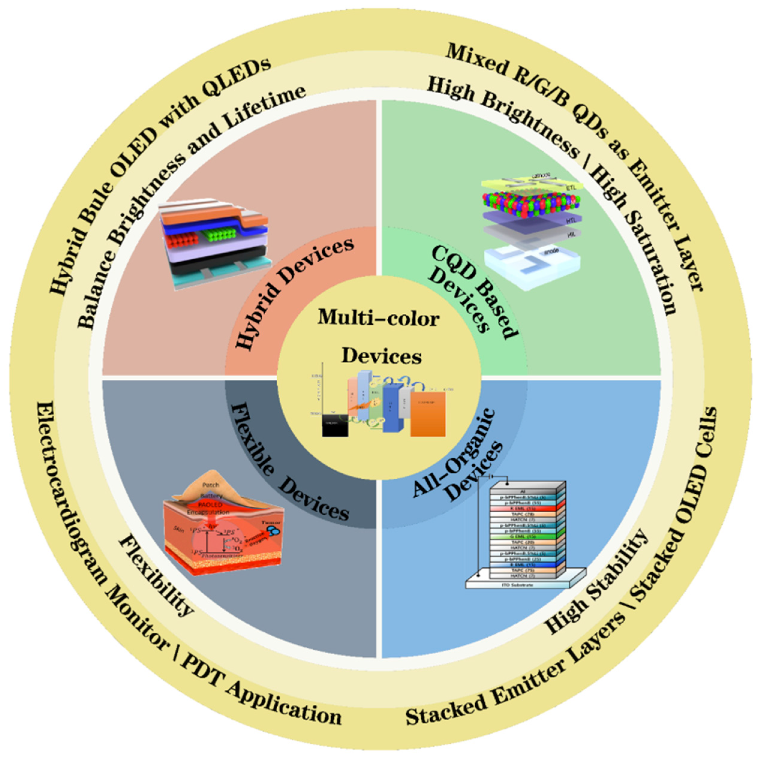
Figure 1. Progress in multi-color devices (PDT: photodynamic therapy).
2. Types of Multi-Color Devices
2.1. Multi-Color OLEDs
OLEDs are expected to play a critical role in solid-state lighting and display application, owing to their unique properties, such as a wide range of colors, excellent luminance, ultrathin thickness, and flexibility. There are different ways to realize multi-color OLED devices. Firstly, the red, green, and blue OLEDs are arranged in parallel to achieve a wide color gamut [13,57][13][38]. However, this method has an intrinsic deficiency of a low pixel density. Secondly, the vertical stack OLED configuration has an improved pixel density and high efficiency. However, the structure of the device is relatively complex, leading to poor stability. Thirdly, the emission of OLEDs with multiple emission layers is selectively activated by different voltages [18,28,58,59,60,61,62,63][18][28][39][40][41][42][43][44]. Still, the transition of the complex exciton region between the two emission layers tends to reduce the device’s efficiency.2.1.1. Side-by-Side Structure
Combining the two, three, or four single-color OLED units in the side-by-side arrangement was proposed, driven by circuitry comprising a thin-film transistor (TFT) and capacitors that can address each pixel independently. The devices exhibit good optical performances since the light directly emits from respective units. In 2003, C. David Muller et al. used a polymer with photoresist properties to make red/green/blue side-by-side OLED units via solution processing, as shown in Figure 2a [17]. The polymers are the classes of oxetane-functionalized spirobifluorene-co-fluorene, and they can be crosslinked photochemically to produce insoluble polymer networks in desired areas. A photograph of a red, green, and blue device is shown in Figure 2b. The obtained red-, green-, and blue-emitting units possess high luminous efficiency (LE) of about 1, 7, and 3 cd A−1, respectively (Figure 2c).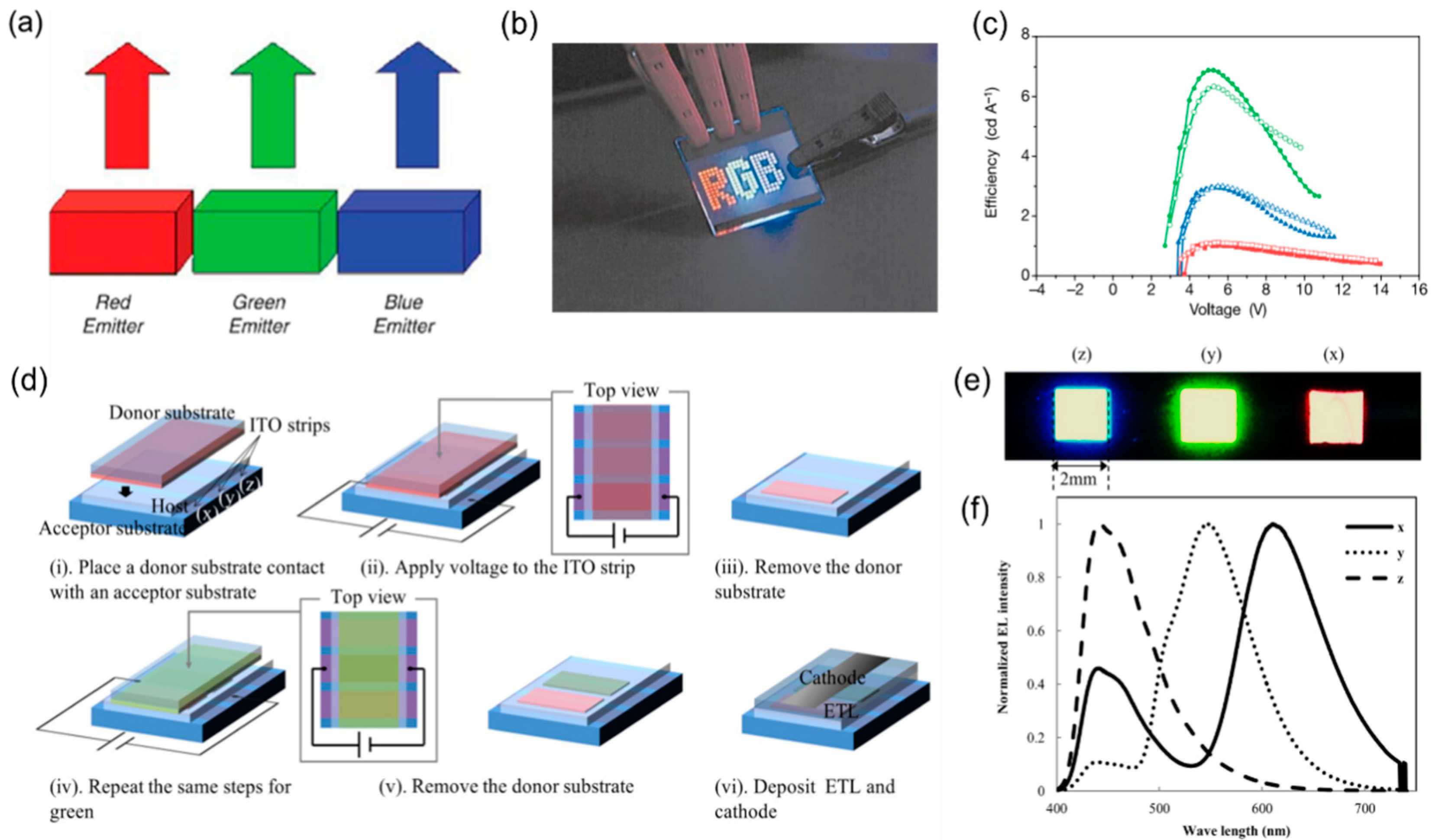
Figure 2. Side-by-Side Structure of Multi-color OLEDs. (a) Directly combine the red, green, and blue emitters in parallel. (b) Photograph of a red, green, and blue device. The dimensions of the glass substrate are 25 × 25 mm. (c) The LE for red-emitting, green-emitting, and blue-emitting devices.
2.1.2. Vertically Stacked OLEDs
Compared with side-by-side red/green/blue OLED units to make a multi-color display, vertically stacked OLED units enable smaller pixel size and more fill factor, resulting in a threefold increased pixel density of the display. However, because of the light loss and the resistance increase in the semitransparent central electrode, the brightness of multi-color OLEDs inevitably decreases and a high drive voltage is needed.Two-Unit Stacked OLEDs
In 1997, P.E. Burrows and S.R. Forrest et al. at Princeton University first proposed a new type of display pixel in which the two OLED units of red, green, or blue emission were placed in a vertically stacked geometry to mix red, green, or blue colors (Figure 3a) [65][46]. For example, independently blue and red emission OLED units are stacked and connected by the central magnesium–silver–indium tin oxide (Mg-Ag-ITO) electrode. The central electrode works as a common carrier injection layer of two units, and the color continuously changes from deep red to blue depending on the voltage bias ratio. On this basis, in 2009, C.J. Liang et al. achieved highly efficient multi-color emission with two-unit stacked OLEDs (Figure 3b) [9]. They found that the thin organic film underlying the ITO layer would be harmed by the magnetron sputtering process; thus, they solely adopted an aluminum–gold (Al-Au) dual film with suitable thickness as the inter-mediate electrode and, to improve the balance of electrons and holes injection, at both ends of the electrode they increased lithium fluoride (LiF) as the electron injection buffer layer and F4TCNQ-doped m-MTDATA as the hole injection buffer layer. However, adopting a traditional metallic conductor as an intermediate layer does not only reduce transparency but also influences stability. An effective way to reduce the driving voltages of tandem structures is by replacing them with a charge generation layer (CGL). In 2013, Yongbiao Zhao et al. from Nanyang technological university inserted a p-type layer of molybdenum trioxide (MoO3) between hole transport layer TCTA constituting an n-i-p-i-n heterojunction symmetric structure (Figure 3d) [66][47]. When applying an alternating current (AC) signal, the n-i-p junction and p-i-n junction would switch on alternatively, and the device-emitted light mixed with two stacked OLED units. The correlated color temperature (CCT) of this device could be changed from 7575 to 2773 K, and the Commission Internationale de l’Eclairage (CIE) was varied from (0.16, 0.32) to (0.61, 0.38). Although the efficiency of carrier injection has been promoted, the diffusion of dopants would deteriorate the properties of devices. In 2022, Qian Chang et al. used two purely organic materials HAT-CN and CuPc composing a p-n type CGL as shown in Figure 3c; this device not only had better current efficiency but also realized color-tunable stacked OLEDs in a single direct current (DC) signal. When applying a driving voltage, p-n type CGL would generate two type carriers, and two OLED units emitted light simultaneously; the CE and EQE of obtained QLEDs can reach up to 46.3 cd A−1 and 15.1%, respectively [67][48].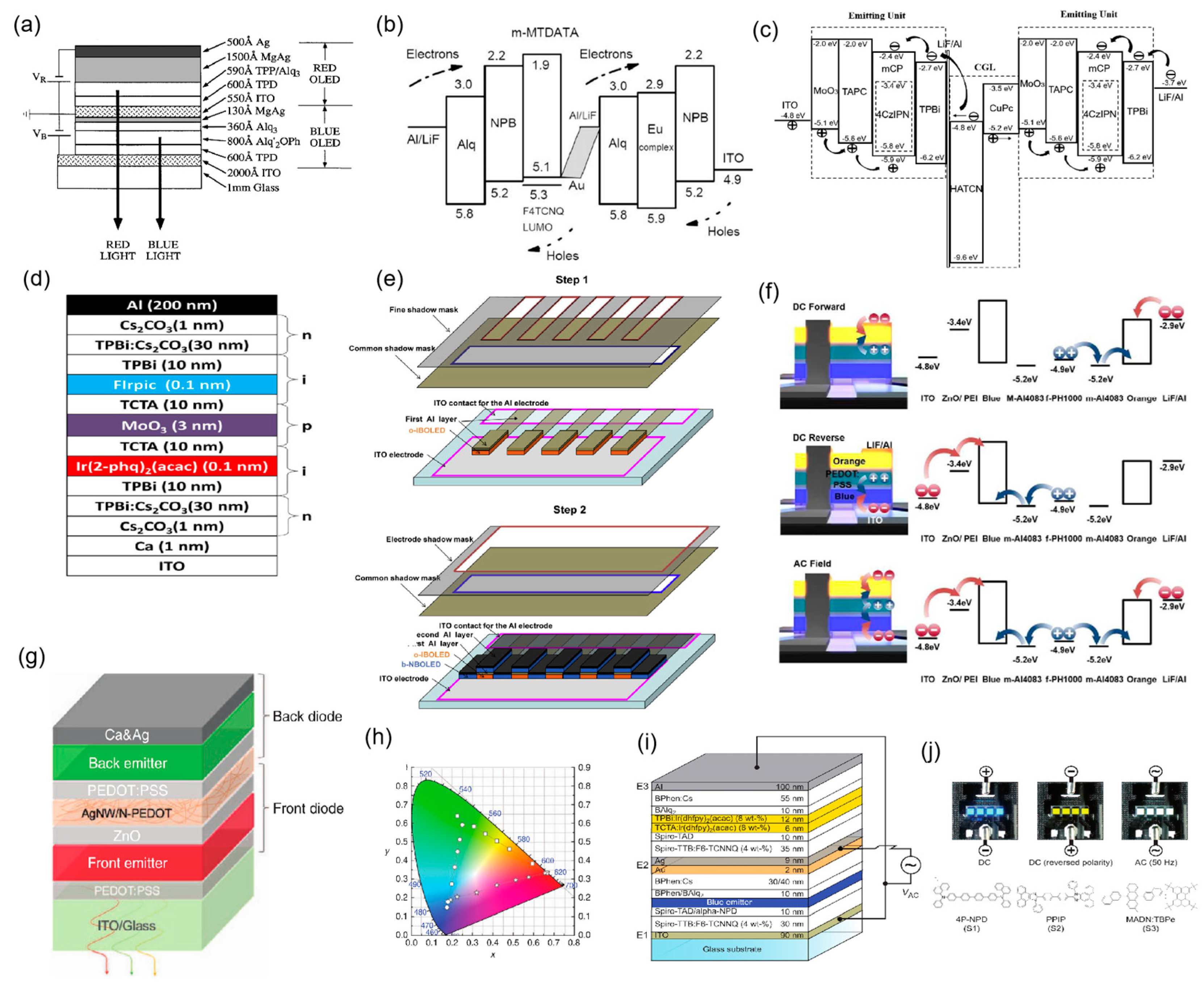
Figure 3. Two−Unit Stacked OLEDs. (a) Schematic cross−section of the layers of a red−blue tunable OLED. (b) The energy level diagram shows the highest occupied molecular orbital (HOMO) and the deeper lowest unoccupied molecular orbital (LUMO) levels, and carrier flows in OLEDs. (c) The working principle of the tandem device. (d) Schematic n-i-p-i-n structure of the OLEDs (e) Fabrication steps of the proposed color−tunable OLED. The o−IBOLED is first deposited with a fine mask, followed by depositing the b−NBOLED without the fine mask. (f) The operation mechanism of top orange and bottom blue tandem LEDs coupled with energy−level alignment under DC forward, DC reverse, and AC fields.
Three-Unit Stacked OLEDs
Three-unit stacked OLED devices are proposed due to the better color gamut and higher CRI compared with the two-unit stacked ones. However, the higher driving voltages for independently controlling three units are inevitably applied. Aside from this, serious color distortion issues appear caused by the micro-cavity effect. In 2017, Mi Jin Park et al. successfully fabricated highly efficient three-stacked OLEDs based on the optical simulation results (Figure 4a); the measured spectrum was almost identical to the simulated device as shown in Figure 4b, showing an EQE of 49.4%, a PE of 33.4 lm W−1, and a CRI of 93 (Figure 4c) [18]. In 2018, Hyunkoo Lee et al. also fabricated multi-color OLEDs with a vertical stack of three primary colors [61][42]. To reduce the driving voltage, they inverted the middle green OLED which shared metal electrodes with the bottom and the top OLEDs (Figure 4d). The driving voltages of blue, green, and red emission units are around 5.3 V, 2.8 V, and 4.4 V, respectively, at 1000 cd m−2 (Figure 4e). The CCT could be easily changed from warm white to cool white and a CRI of 88.7 could be reached. Furthermore, they also optimized the thickness of the hole transport layers (HTLs) and the electron transport layer (ETL) to alleviate the micro-cavity effect. As a result, the color distortion issues are alleviated and the EQE of blue, green, and red emission units can reach 11.1%, 10.9%, and 9.6%, respectively (Figure 4f).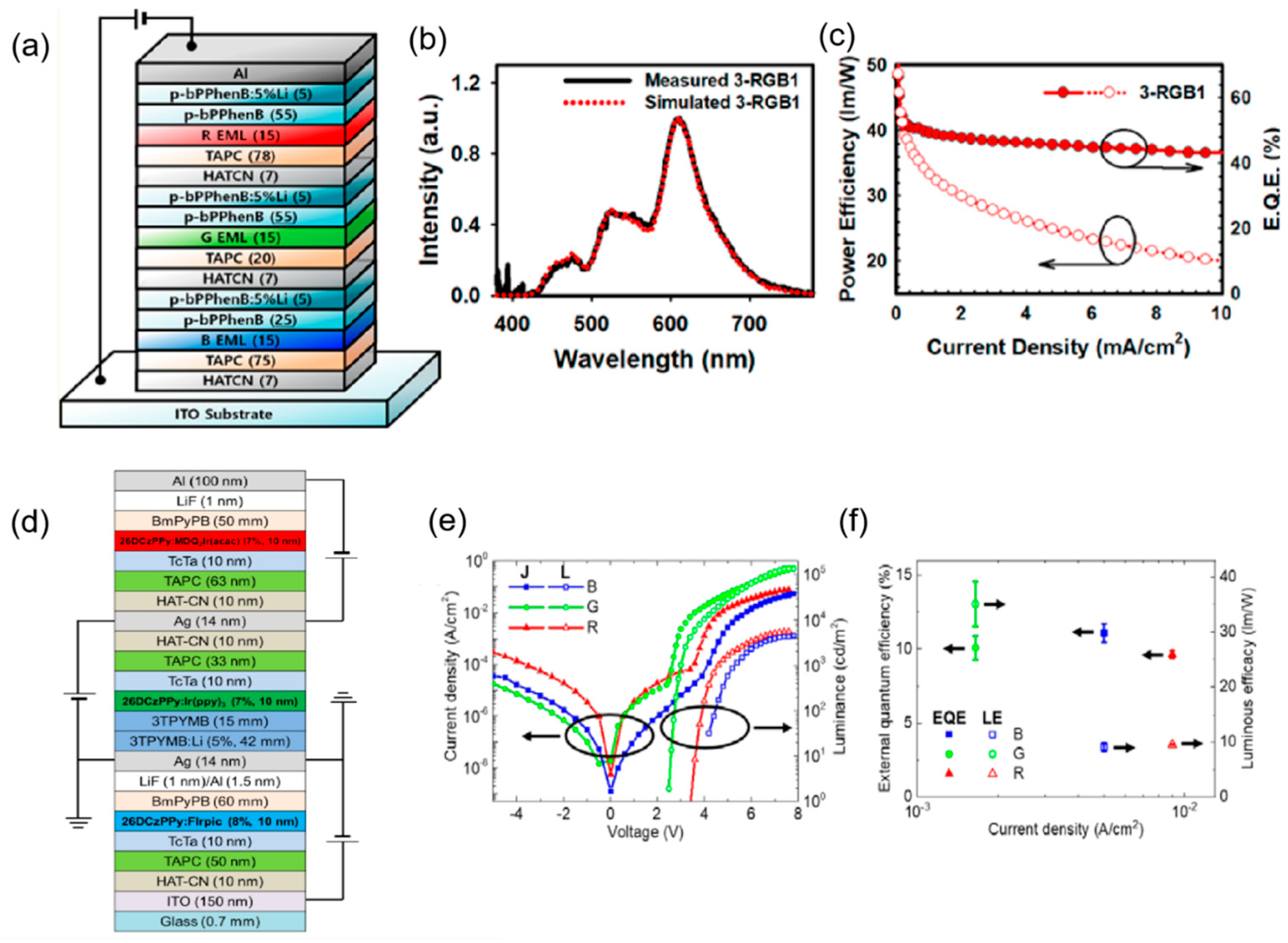
Figure 4. Three-Unit Stacked OLEDs. (a) Schematic structure of the color-tunable OLED. (b) Comparison of measured and simulated EL spectra of the device. (c) PE and EQE versus the current density of the device. Reprinted with permission from Ref. [18]. 2017, ACS Photonics. (d) Schematic structure of the color-tunable OLED with independently controlled red, green, and blue OLEDs. (e) Luminance and current density versus voltage characteristics of independently controlled red, green, and blue OLEDs in the color-tunable OLED. (f) EQE and LE of independently controlled red, green, and blue OLEDs in the color-tunable OLED. Reprinted from Ref. [61][42]. 2018, Optical Express.
2.1.3. Stacked Emitter Layers
Stacking various emitter layers with different emission wavelengths is a direct and simple way to achieve multi-color emission compared with side-by-side and vertically stacked OLED units. In this way, multiple colors can be obtained by changing the bias voltages. To make carriers’ injection more balanced and emission of OLEDs more efficient with stacked emission layers, the energy level structure should be carefully designed and the energy transfer between the host and dopant should be considered.Single Emission Layer
The multi-color OLED with a single emission layer (S-EML) has a simple structure, and it can be fabricated by an all-solution method suitable for commercial applications. By doping multi-emission wavelength materials into the host emission layer, the different colors can be emitted by changing the bias of voltage. In addition, the emission spectrum is influenced by the doped ratios; therefore, the concentration of dopants should be considered and optimized. In 1994, J. Kido and K. Hongawa et al. first proposed the white OLEDs by using a single emitter layer doped with three fluorescent dyes [69][50]. The fluorescent dyes including blue-emitting 1,1,4,4-tetraphenyl-1,3-butadiene, green-emitting coumarin 6, and orange-emitting DCM 1 were doped into the poly(9-vinylcarbazole) (PVK) layer (Figure 5a). The obtained OLEDs possessed high luminance of 3400 cd m−2 at a driving voltage of 14 V and an excellent LE of 0.85 lm W−1.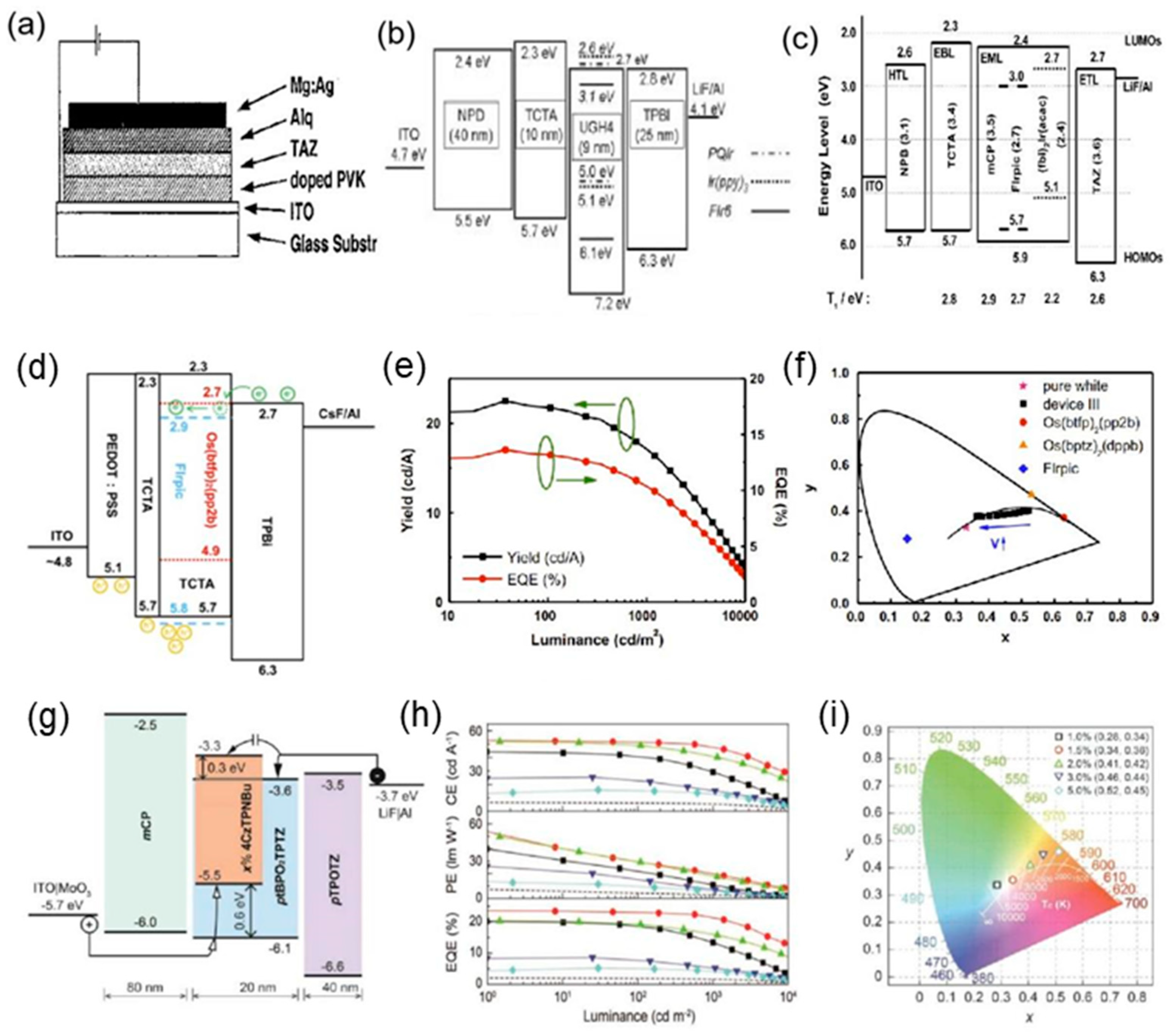
Figure 5. Single Emission Layer of Multi-color OLEDs. (a) The configuration of the OLED cell. Reprinted with permission from Ref. [69][50]. 1994, Applied Physics Letters. (b) The schematic diagram of the energy structure. Reprinted with permission from Ref. [70][51]. 2004, Wiley-VCH. (c) Proposed energy diagram of the white OLED. Reprinted with permission from Ref. [71][52]. 2008, John Wiley and Sons. (d) Energy band diagram of the materials in the device. (e) CE and EQE characteristics versus luminance of device. (f) CIE 1931 coordinates shifting with applied voltages from 4.7 V to 5.0 V. Reprinted with permission from Ref. [72][53]. 2015, Elsevier (g) The schematic diagram of the energy structure. (h) CE, PE, and EQE versus luminance of OLEDs with different blue TADF doping concentrations. (i) CIE 1931 coordinates’ dependence of the devices on the concentration of dopant. The black body locus and the color temperature lines were added for reference. Reprinted with permission from Ref. [73][54]. 2020, John Wiley and Sons.
Double Emission Layers
Multi-color OLEDs with a double emission layer (D-EML) concept were first introduced by X. Zhou et al. in 2002 [74][55]. For OLEDs with S-EMLs, electrons or holes tend to accumulate at the interface of the EML/ETL or EML/HTL due to the large energy barrier. The high density of accumulated carriers leads to the quenching of triplet excitons. In contrast, the D-EML structure can significantly avoid carrier accumulation at the interface by widening the triplet excitons’ generation zone, leading to better device performance. In 2004, Gufeng He et al. fabricated an efficient OLED with D-EML structure through doping the same phosphorescent material Ir(ppy)3 into both TCTA and TAZ emission hosts (Figure 6a) [75][56]. Because the HOMO level of the TCTA was much lower than that of Ir(ppy)3, a part of the holes would be captured by the Ir(ppy)3; in this way, excitons not only formed on the interface of TCTA and TAZ, but also could be combined in the Ir(ppy)3 sites directly. This structure increased the recombination area, resulting in an excellent performance with PE of 64 lm W−1 at 1000 cd m−2 and EQE of 19.3% (Figure 6b). To broaden the range of colors, in 2010, Sebastian Reineke et al. embedded the blue and green dopants in a common host of TPBi, and the red one in the host of TCTA to achieve D-EML-structured multi-color OLEDs (Figure 6c) [76][57]. The PE of obtained OLEDs can reach 90 lm W−1 at the brightness of 1000 cd m−2, and the EQE can reach 34% (Figure 6d). In 2016, Xuming Zhuang et al. reported a four-color OLED device employing a D-EML structure with a blue host/orange dopant and green host/red dopant; they avoided using the structure of only the dopant as the emitting molecules, and achieved the most broad range of spectra with the D-EML structure, exhibiting a high CRI of 92, EQE of 23.3%, and PE of 63.2 lm W−1 (Figure 6e,f) [59][40].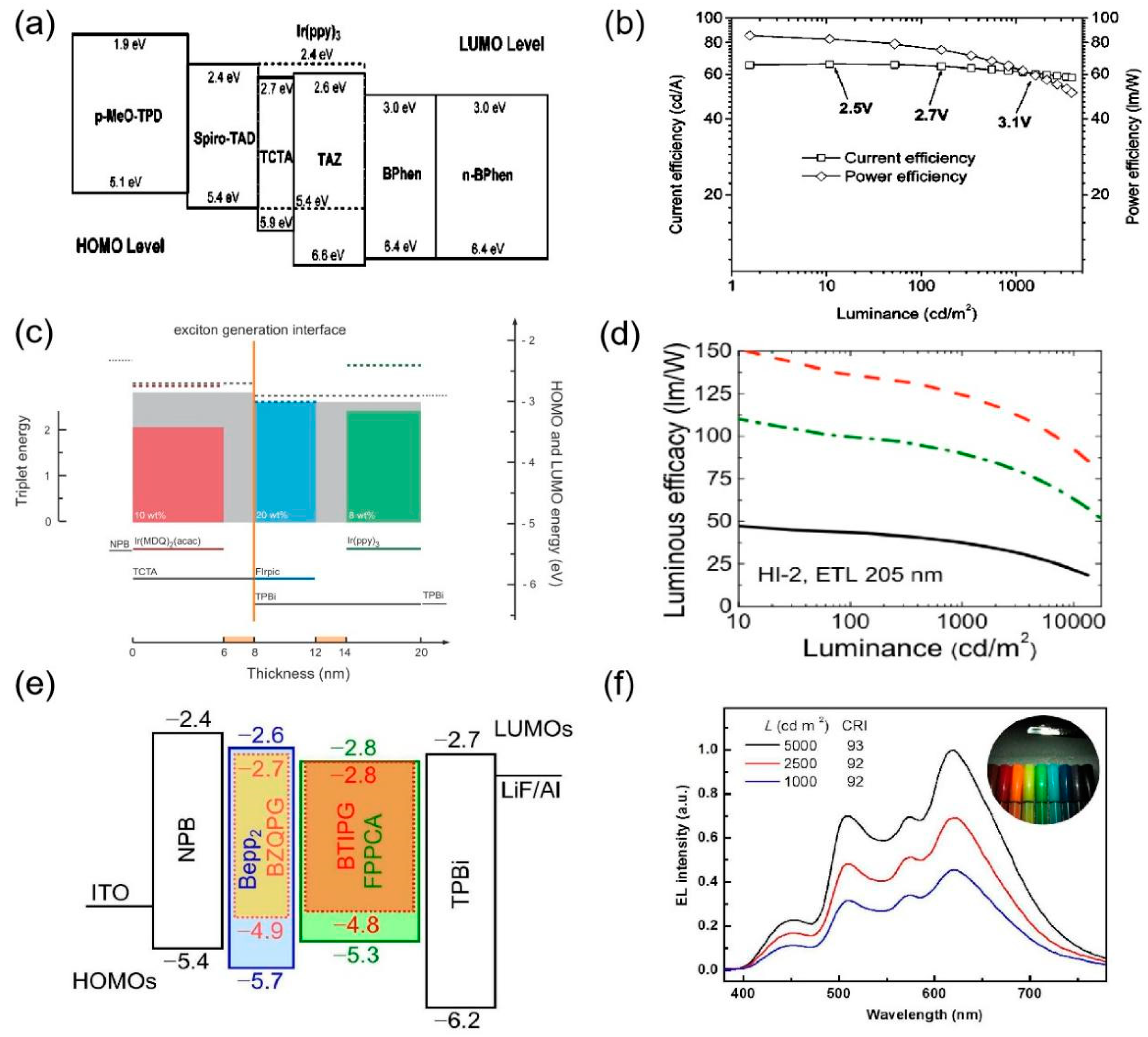
Figure 6. Double Emission Layers of Multi-color OLEDs. (a) Device structure of D-EML p-i-n OLED and the proposed energy level diagram. (b) The current efficiencies (square) and power efficiencies (diamond) of an optimized D-EML OLED. Reprinted with permission from Ref. [75][56]. 2004, AIP Publishing. (c) Energy diagram of the materials used in OLEDs. (d) EL spectra and the corresponding CRI values of the device at different luminance. Reprinted with permission from Ref. [76][57]. 2009, Springer Nature. (e) Emission layer energy level diagram. HOMO and LUMO levels are plotted as solid and dashed lines, respectively, and filled boxes refer to the materials’ triplet energies. The orange line indicates the exciton generation interface. The orange x-axis marks intrinsic interlayers (f) The LE of the device as a function of luminance. These values are measured in three configurations: flat (without outcoupling solid), with an attached half-sphere (dash), and with an attached pyramidal pattern (dash–dot). Reprinted with permission from Ref. [59][40]. 2016, ACS.
Multiple Emission Layers
To further improve the balance of the carrier injection, it is necessary to develop color-tunable OLEDs with multiple emission layers. In 2016, Ping Chen et al. from Jilin University fabricated OLEDs with double blue emission layers and an orange ultrathin layer between them [60][41]. TCTA with high hole transport mobility and TPBi with high electron transport mobility were blended as the mixed host for the blue phosphorescent emitter (Figure 7a). Two different hosts expand the exciton recombination zone, which leads to charge balance. Normalized EL spectra of the device at different voltages from 3 V to 9 V are shown in Figure 7b. The peak PE can be above 40.8 lm W−1, and a CRI of 62 and CE of 39.8 cd A−1 can be achieved. In 2018, Gyeong Woo Kim et al. also adopted the blue–yellow–blue multiple EML structure while they selected the TADF material as a blue emitter (Figure 7c), achieving a high EQE of 23.1% at the CIE coordinate of (0.324, 0.337) [77][58]. Normalized EL spectra of devices are presented in Figure 7d. Although sandwiching single-color emission layers between two blue emission layers has obtained stable multi-color emission, it is essential to increase three or more emitters to achieve wider luminescent spectra. In 2019, Baiqian Wang et al. fabricated a relatively stable white OLED with two emission layers of both blue dopants, and three ultrathin layers of red, orange, and green emission layers in the middle (Figure 7e) [63][44]. The obtained OLEDs have ambipolar charge carrier transport properties between EMLs. Normalized EL spectra of the device at different driving voltages are shown in Figure 7f. The performance of OLEDs is excellent with CRI reaching 94 and a maximum PE of 33.4 lm W−1.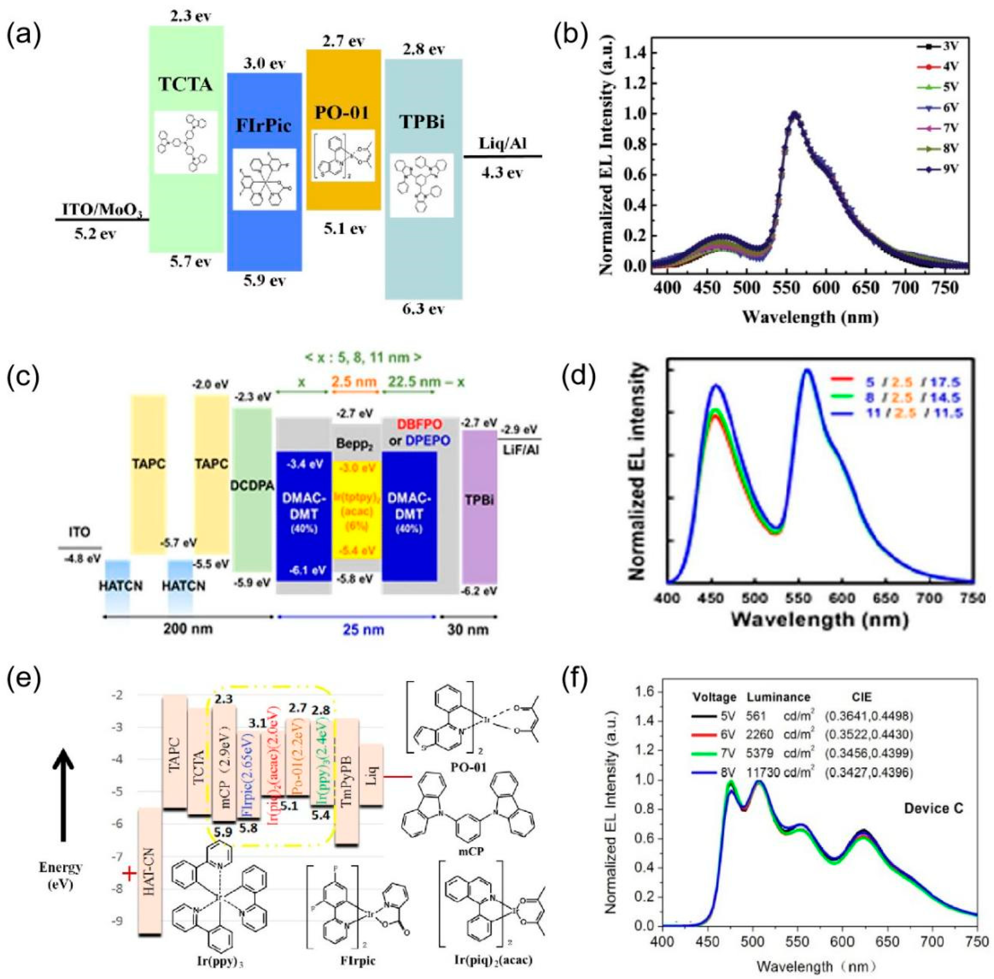
Figure 7. Multiple Emission Layers of Multi-color OLEDs. (a) The detailed energy level diagram and chemical structures of the materials. (b) Normalized EL spectra of the device at different voltages from 3 V to 9 V. Reprinted with permission from Ref. [60][41]. 2016, Elsevier. (c) Energy level diagram with the detailed device structure of OLEDs. (d) Normalized EL spectra of white devices. Reprinted with permission from Ref. [77][58]. 2018, Springer Nature. (e) The schematic diagram of devices and the energy level/molecular structure of part materials. (f) Normalized EL spectra of the device at different driving voltages. Reprinted with permission from Ref. [63][44]. 2019, Elsevier.
References
- Chang, M.H.; Das, D.; Varde, P.V.; Pecht, M. Light Emitting Diodes Reliability Review. Microelectron. Reliab. 2012, 52, 762–782.
- Wang, R.; Xiang, H.; Chen, J.; Li, Y.; Zhou, Y.; Choy, W.C.H.; Fan, Z.; Zeng, H. Energy Regulation in White-Light-Emitting Diodes. ACS Energy Lett. 2022, 7, 2173–2188.
- Wu, Y.; Ma, J.; Su, P.; Zhang, L.; Xia, B. Full-Color Realization of Micro-Led Displays. Nanomaterials 2020, 10, 2482.
- Huang, Y.; Hsiang, E.L.; Deng, M.Y.; Wu, S.T. Mini-LED, Micro-LED and OLED Displays: Present Status and Future Perspectives. Light Sci. Appl. 2020, 9, 105.
- Ma, L.; Shao, Y.F. A brief review of innovative strategies towards structure design of practical electronic display device. J. Cent. South Univ. 2022, 27, 1624–1644.
- Koo, J.H.; Jeong, S.; Shim, H.J.; Son, D.; Kim, J.; Kim, D.C.; Choi, S.; Hong, J.I.; Kim, D.H. Wearable Electrocardiogram Monitor Using Carbon Nanotube Electronics and Color-Tunable Organic Light-Emitting Diodes. ACS Nano 2017, 11, 10032–10041.
- Jeon, Y.; Noh, I.; Seo, Y.C.; Han, J.H.; Park, Y.; Cho, E.H.; Choi, K.C. Parallel-Stacked Flexible Organic Light-Emitting Diodes for Wearable Photodynamic Therapeutics and Color-Tunable Optoelectronics. ACS Nano 2020, 14, 15688–15699.
- Mao, M.; Lam, T.L.; To, W.P.; Lao, X.; Liu, W.; Xu, S.; Cheng, G.; Che, C.M. Stable, High-Efficiency Voltage-Dependent Color-Tunable Organic Light-Emitting Diodes with a Single Tetradentate Platinum(II) Emitter Having Long Operational Lifetime. Adv. Mater. 2021, 33, e2004873.
- Liang, C.J.; Choy, W.C.H. Tunable Full-Color Emission of Two-Unit Stacked Organic Light Emitting Diodes with Dual-Metal Intermediate Electrode. J. Organomet. Chem. 2009, 694, 2712–2716.
- Nakamura, K.; Ishikawa, T.; Nishioka, D.; Ushikubo, T.; Kobayashi, N. Color-Tunable Multilayer Organic Light Emitting Diode Composed of DNA Complex and Tris(8-Hydroxyquinolinato)Aluminum. Appl. Phys. Lett. 2010, 97, 95–98.
- Tsuzuki, T.; Tokito, S. Highly Efficient, Low-Voltage Phosphorescent Organic Light-Emitting Diodes Using an Iridium Complex as the Host Material. Adv. Mater. 2007, 19, 276–280.
- Jiang, Y.; Lian, J.; Chen, S.; Kwok, H.S. Fabrication of Color Tunable Organic Light-Emitting Diodes by an Alignment Free Mask Patterning Method. Org. Electron. 2013, 14, 2001–2006.
- Geffroy, B.; le Roy, P.; Prat, C. Organic Light-Emitting Diode (OLED) Technology: Materials, Devices and Display Technologies. Polym. Int. 2006, 55, 572–582.
- Gayral, B. LEDs for Lighting: Basic Physics and Prospects for Energy Savings. Comptes Rendus Phys. 2017, 18, 453–461.
- Kanno, H.; Hamada, Y.; Takahashi, H. Development of OLED with High Stability and Luminance Efficiency by Co-Doping Methods for Full Color Displays. IEEE J. Sel. Top. Quantum Electron. 2004, 10, 30–36.
- Schwartz, G.; Reineke, S.; Rosenow, T.C.; Walzer, K.; Leo, K. Triplet Harvesting in Hybrid White Organic Light-Emitting Diodes. Adv. Funct. Mater. 2009, 19, 1319–1333.
- Müller, C.D.; Falcou, A.; Reckefuss, N.; Rojahn, M.; Wiederhirn, V.; Rudati, P.; Frohne, H.; Nuyken, O.; Becker, H.; Meerholz, K. Multi-Colour Organic Light-Emitting Displays by Solution Processing. Nature 2003, 421, 829–833.
- Park, M.J.; Son, Y.H.; Yang, H.I.; Kim, S.K.; Lampande, R.; Kwon, J.H. Optical Design and Optimization of Highly Efficient Sunlight-like Three-Stacked Warm White Organic Light Emitting Diodes. ACS Photonics 2018, 5, 655–662.
- Guo, F.; Karl, A.; Xue, Q.F.; Tam, K.C.; Forberich, K.; Brabec, C.J. The Fabrication of Color-Tunable Organic Light-Emitting Diode Displays via Solution Processing. Light Sci. Appl. 2017, 6, e17094.
- Fröbel, M.; Schwab, T.; Kliem, M.; Hofmann, S.; Leo, K.; Gather, M.C. Get It White: Color-Tunable AC/DC OLEDs. Light Sci. Appl. 2015, 4, e247.
- Zhang, J.; Ren, B.; Deng, S.; Huang, J.; Jiang, L.; Zhou, D.; Zhang, X.; Zhang, M.; Chen, R.; Yeung, F.; et al. Voltage-Dependent Multicolor Electroluminescent Device Based on Halide Perovskite and Chalcogenide Quantum-Dots Emitters. Adv. Funct. Mater. 2020, 30, 1907074.
- Zhang, Y.; Xie, C.; Su, H.; Liu, J.; Pickering, S.; Wang, Y.; Yu, W.W.; Wang, J.; Wang, Y.; Hahm, J.I.; et al. Employing Heavy Metal-Free Colloidal Quantum Dots in Solution-Processed White Light-Emitting Diodes. Nano Lett. 2011, 11, 329–332.
- Bae, W.K.; Lim, J.; Lee, D.; Park, M.; Lee, H.; Kwak, J.; Char, K.; Lee, C.; Lee, S. R/G/B/Natural White Light Thin Colloidal Quantum Dot-Based Light-Emitting Devices. Adv. Mater. 2014, 26, 6387–6393.
- Kim, J.H.; Lee, K.H.; Kang, H.D.; Park, B.; Hwang, J.Y.; Jang, H.S.; Do, Y.R.; Yang, H. Fabrication of a White Electroluminescent Device Based on Bilayered Yellow and Blue Quantum Dots. Nanoscale 2015, 7, 5363–5370.
- Wepfer, S.; Frohleiks, J.; Hong, A.R.; Jang, H.S.; Bacher, G.; Nannen, E. Solution-Processed CuInS2-Based White QD-LEDs with Mixed Active Layer Architecture. ACS Appl. Mater. Interfaces 2017, 9, 11224–11230.
- Mu, G.; Rao, T.; Zhang, S.; Wen, C.; Chen, M.; Hao, Q.; Tang, X. Ultrasensitive Colloidal Quantum-Dot Upconverters for Extended Short-Wave Infrared. ACS Appl. Mater. Interfaces 2022, 14, 45553–45561.
- Shen, H.; Gao, Q.; Zhang, Y.; Lin, Y.; Lin, Q.; Li, Z.; Chen, L.; Zeng, Z.; Li, X.; Jia, Y.; et al. Visible quantum dot light-emitting diodes with simultaneous high brightness and efficiency. Nature Photon 2019, 13, 192–197.
- Qasim, K.; Zhenbo, Z.; Khatri, N.K.; Xu, Q.; Subramanian, A.; Qing, L.; Wei, L. A Color Tunable Quantum-Dot Light-Emitting Diode Device Driven by Variable Voltage. J. Nanosci. Nanotechnol. 2018, 19, 1038–1043.
- Wang, O.; Wang, L.; Li, Z.; Xu, Q.; Lin, Q.; Wang, H.; Du, Z.; Shen, H.; Li, L.S. High-Efficiency, Deep Blue ZnCdS/Cd: XZn1- XS/ZnS Quantum-Dot-Light-Emitting Devices with an EQE Exceeding 18%. Nanoscale 2018, 10, 5650–5657.
- Li, X.; Lin, Q.; Song, J.; Shen, H.; Zhang, H.; Li, L.S.; Li, X.; Du, Z. Quantum-Dot Light-Emitting Diodes for Outdoor Displays with High Stability at High Brightness. Adv. Opt. Mater. 2020, 8, 1901145.
- Cao, W.; Xiang, C.; Yang, Y.; Chen, Q.; Chen, L.; Yan, X.; Qian, L. Highly Stable QLEDs with Improved Hole Injection via Quantum Dot Structure Tailoring. Nat. Commun. 2018, 9, 2608.
- Kang, H.L.; Kang, J.; Won, J.K.; Jung, S.M.; Kim, J.; Park, C.H.; Ju, B.K.; Kim, M.G.; Park, S.K. Spatial Light Patterning of Full Color Quantum Dot Displays Enabled by Locally Controlled Surface Tailoring. Adv. Opt. Mater. 2018, 6, 1701335.
- Lee, K.H.; Han, C.Y.; Kang, H.D.; Ko, H.; Lee, C.; Lee, J.; Myoung, N.S.; Yim, S.Y.; Yang, H. Highly Efficient, Color-Reproducible Full-Color Electroluminescent Devices Based on Red/Green/Blue Quantum Dot-Mixed Multilayer. ACS Nano 2015, 9, 10941–10949.
- Mei, W.; Zhang, Z.; Zhang, A.; Li, D.; Zhang, X.; Wang, H.; Chen, Z.; Li, Y.; Li, X.; Xu, X. High-Resolution, Full-Color Quantum Dot Light-Emitting Diode Display Fabricated via Photolithography Approach. Nano Res. 2020, 13, 2485–2491.
- Mu, G.; Rao, T.; Chen, M.; Tan, Y.; Hao, Q.; Hao, Q.; Tang, X. Colloidal Quantum-Dot Light Emitting Diodes with Bias-Tunable Color. Photonics Res. 2022, 10, 1633–1639.
- Lee, S.; Hahm, D.; Yoon, S.Y.; Yang, H.; Bae, W.K.; Kwak, J. Quantum-Dot and Organic Hybrid Light-Emitting Diodes Employing a Blue Common Layer for Simple Fabrication of Full-Color Displays. Nano Res. 2022, 15, 6477–6482.
- Zhang, H.; Su, Q.; Chen, S. Quantum-Dot and Organic Hybrid Tandem Light-Emitting Diodes with Multi-Functionality of Full-Color-Tunability and White-Light-Emission. Nat. Commun. 2020, 11, 2826–2833.
- Niikura, H.; Légaré, F.; Hasbani, R.; Ivanov, M.Y.; Villeneuve, D.M.; Corkum, P.B. Probing Molecular Dynamics with Attosecond Resolution Using Correlated Wave Packet Pairs. Nature 2003, 421, 826–829.
- Wu, S.; Li, S.; Sun, Q.; Huang, C.; Fung, M.K. Highly Efficient White Organic Light-Emitting Diodes with Ultrathin Emissive Layers and a Spacer-Free Structure. Sci. Rep. 2016, 6, 25821.
- Zhuang, X.; Zhang, H.; Ye, K.; Liu, Y.; Wang, Y. Two Host-Dopant Emitting Systems Realizing Four-Color Emission: A Simple and Effective Strategy for Highly Efficient Warm-White Organic Light-Emitting Diodes with High Color-Rendering Index at High Luminance. ACS Appl. Mater. Interfaces 2016, 8, 11221–11225.
- Chen, P.; Chen, B.; Zuo, L.; Duan, Y.; Han, G.; Sheng, R.; Xue, K.; Zhao, Y. High-Efficiency and Superior Color-Stability White Phosphorescent Organic Light-Emitting Diodes Based on Double Mixed-Host Emission Layers. Org. Electron. 2016, 31, 136–141.
- Lee, H.; Cho, H.; Byun, C.-W.; Han, J.-H.; Kwon, B.-H.; Choi, S.; Lee, J.; Cho, N.S. Color-Tunable Organic Light-Emitting Diodes with Vertically Stacked Blue, Green, and Red Colors for Lighting and Display Applications. Opt. Express 2018, 26, 18351.
- Wu, J.Y.; Chen, S.A. Development of a Highly Efficient Hybrid White Organic-Light-Emitting Diode with a Single Emission Layer by Solution Processing. ACS Appl. Mater. Interfaces 2018, 10, 4851–4859.
- Wang, B.; Kou, Z.; Tang, Y.; Yang, F.; Fu, X.; Yuan, Q. High CRI and Stable Spectra White Organic Light-Emitting Diodes with Double Doped Blue Emission Layers and Multiple Ultrathin Phosphorescent Emission Layers by Adjusting the Thickness of Spacer Layer. Org. Electron. 2019, 70, 149–154.
- Kajiyama, Y.; Kajiyama, K.; Aziz, H. Maskless RGB Color Patterning of Vacuum-Deposited Small Molecule OLED Displays by Diffusion of Luminescent Dopant Molecules. Opt. Express 2015, 23, 16650.
- Burrows, P.E.; Forrest, S.R.; Sibley, S.P.; Thompson, M.E. Color-Tunable Organic Light-Emitting Devices. Appl. Phys. Lett. 1996, 69, 2959–2961.
- Zhao, Y.; Chen, R.; Gao, Y.; Leck, K.S.; Yang, X.; Liu, S.; Abiyasa, A.P.; Divayana, Y.; Mutlugun, E.; Tan, S.T.; et al. AC-Driven, Color- and Brightness-Tunable Organic Light-Emitting Diodes Constructed from an Electron Only Device. Org. Electron. 2013, 14, 3195–3200.
- Chang, Q.; Lü, Z.; Yin, Y.; Xiao, J.; Wang, J. Highly Efficient Tandem OLED Based on a Novel Charge Generation Layer of HAT-CN/CuPc Heterojunction. Displays 2022, 75, 102306.
- Cho, S.H.; Kim, E.H.; Jeong, B.; Lee, J.H.; Song, G.; Hwang, I.; Cho, H.; Kim, K.L.; Yu, S.; Kim, R.H.; et al. Solution-Processed Electron-Only Tandem Polymer Light-Emitting Diodes for Broad Wavelength Light Emission. J. Mater. Chem. C 2017, 5, 110–117.
- Kido, J.; Hongawa, K.; Okuyama, K.; Nagai, K. White Light-Emitting Organic Electroluminescent Devices Using the Poly(N-Vinylcarbazole) Emitter Layer Doped with Three Fluorescent Dyes. Appl. Phys. Lett. 1994, 64, 815–817.
- D’Andrade, B.W.; Holmes, R.J.; Forrest, S.R. Efficient Organic Electrophosphorescent White-Light-Emitting Device with a Triple Doped Emissive Layer. Adv. Mater. 2004, 16, 624–628.
- Wang, Q.; Ding, J.; Dongge, M.; Cheng, Y.; Wang, L.; Jing, X.; Wang, F. Harvesting Excitons via Two Parallel Channels for Efficient White Organic LEDs with Nearly 100% Internal Quantum Efficiency: Fabrication and Emission-Mechanism Analysis. Adv. Funct. Mater. 2009, 19, 84–95.
- Huang, M.H.; Lin, W.C.; Fan, C.C.; Wang, Y.S.; Lin, H.W.; Liao, J.L.; Lin, C.H.; Chi, Y. Tunable Chromaticity Stability in Solution-Processed Organic Light Emitting Devices. Org. Electron. 2015, 20, 36–42.
- Ding, D.; Wang, Z.; Li, C.; Zhang, J.; Duan, C.; Wei, Y.; Xu, H. Highly Efficient and Color-Stable Thermally Activated Delayed Fluorescence White Light-Emitting Diodes Featured with Single-Doped Single Emissive Layers. Adv. Mater. 2020, 32, e1906950.
- Zhou, X.; Qin, D.S.; Pfeiffer, M.; Blochwitz-Nimoth, J.; Werner, A.; Drechsel, J.; Maennig, B.; Leo, K.; Bold, M.; Erk, P.; et al. High-Efficiency Electrophosphorescent Organic Light-Emitting Diodes with Double Light-Emitting Layers. Appl. Phys. Lett. 2002, 81, 4070–4072.
- He, G.; Pfeiffer, M.; Leo, K.; Hofmann, M.; Birnstock, J.; Pudzich, R.; Salbeck, J. High-Efficiency and Low-Voltage p-i-n Electrophosphorescent Organic Light-Emitting Diodes with Double-Emission Layers. Appl. Phys. Lett. 2004, 85, 3911–3913.
- Reineke, S.; Lindner, F.; Schwartz, G.; Seidler, N.; Walzer, K.; Lüssem, B.; Leo, K. White Organic Light-Emitting Diodes with Fluorescent Tube Efficiency. Nature. 2009, 459, 234–238.
- Kim, G.W.; Bae, H.W.; Lampande, R.; Ko, I.J.; Park, J.H.; Lee, C.Y.; Kwon, J.H. Highly Efficient Single-Stack Hybrid Cool White OLED Utilizing Blue Thermally Activated Delayed Fluorescent and Yellow Phosphorescent Emitters. Sci. Rep. 2018, 8, 16263.
More