Your browser does not fully support modern features. Please upgrade for a smoother experience.
Please note this is a comparison between Version 2 by Sirius Huang and Version 1 by Achraf SAADAOUI.
The ultra-fast charging of batteries is a major issue in electric mobility development globally. Research in the area of power electronics for electric vehicle charging applications is focused on new high-power chargers. These chargers will significantly increase the charging power of electric vehicles, which will reduce the charging time. Furthermore, electric vehicles can be deployed to achieve improved efficiency and high-quality power if vehicle to microgrid (V2µG) is applied.
- ultra-fast charger
- DC-DC converter
- rectifier
- electric vehicles
- off-board charger
1. Types of Fast Charging Methods
Charging is the process of providing a battery with DC current from an outside energy source, including a chemical reaction that stores the electrical energy in the form of chemical energy. To enhance the results of this charging both in time and efficiency, different charging methods and processes are applied.
One of the most common fast-charging methods is the constant current–constant voltage (CC-CV) charging. As shown in Figure 1a, a constant current (IBref) is provided to the electric vehicle battery until the maximum acceptable voltage (VBref) is reached. Then, this voltage is regulated to stay constant until the current achieves a cut-off current (ICO) [23][1]. The charging time of the battery can be minimized by increasing the current used during the constant current phase. However, high currents can reduce the lifetime of the battery or create damage on a permanent basis. In fact, the use of a higher current leads to higher losses because of the internal resistance of the battery. These losses are mainly manifested in the form of an increase in temperature in the battery. Consequently, fast charging necessitates an appropriate thermal management, keeping the temperature of the battery in its safe operating zone [24][2].

Figure 1.
Fast charging methods: (
a
) CC-CV charging method; (
b
) MSCC method.
Another popular fast-charging method is multi-stage constant current (MSCC) charging, as shown in Figure 1b. The CV stage of the CC-CV method is substituted by a sequence of CC phases with monotonic falling charging currents (IBref1 > IBref2 >…> ICO). Each time the battery voltage reaches VBref, the charging current is decreased to the next level. This decrease of current will continue until the battery terminal voltage reaches the maximum acceptable voltage (VBref) under the condition of minimum current (ICO) [25][3]. The charging time of this type of method is a little slower than that of the CC-CV process, with the same initial charging current [26][4].
Recently, a new ultra-fast charging method was developed, called the KVI Non-Linear Voltammetry solution. This process charges the battery in six minutes while maintaining low temperatures (<50 °C) and ensuring a long lifetime of the battery [27][5].
For controlling the voltage and current profiles of the charger output during the charging process, the electric vehicle must be equipped with a Battery Management System (BMS). As presented in Figure 2, this system monitors the voltage of each cell and the temperature, and it gives current and voltage references to the electric vehicle ultra-fast charger controller [28][6].
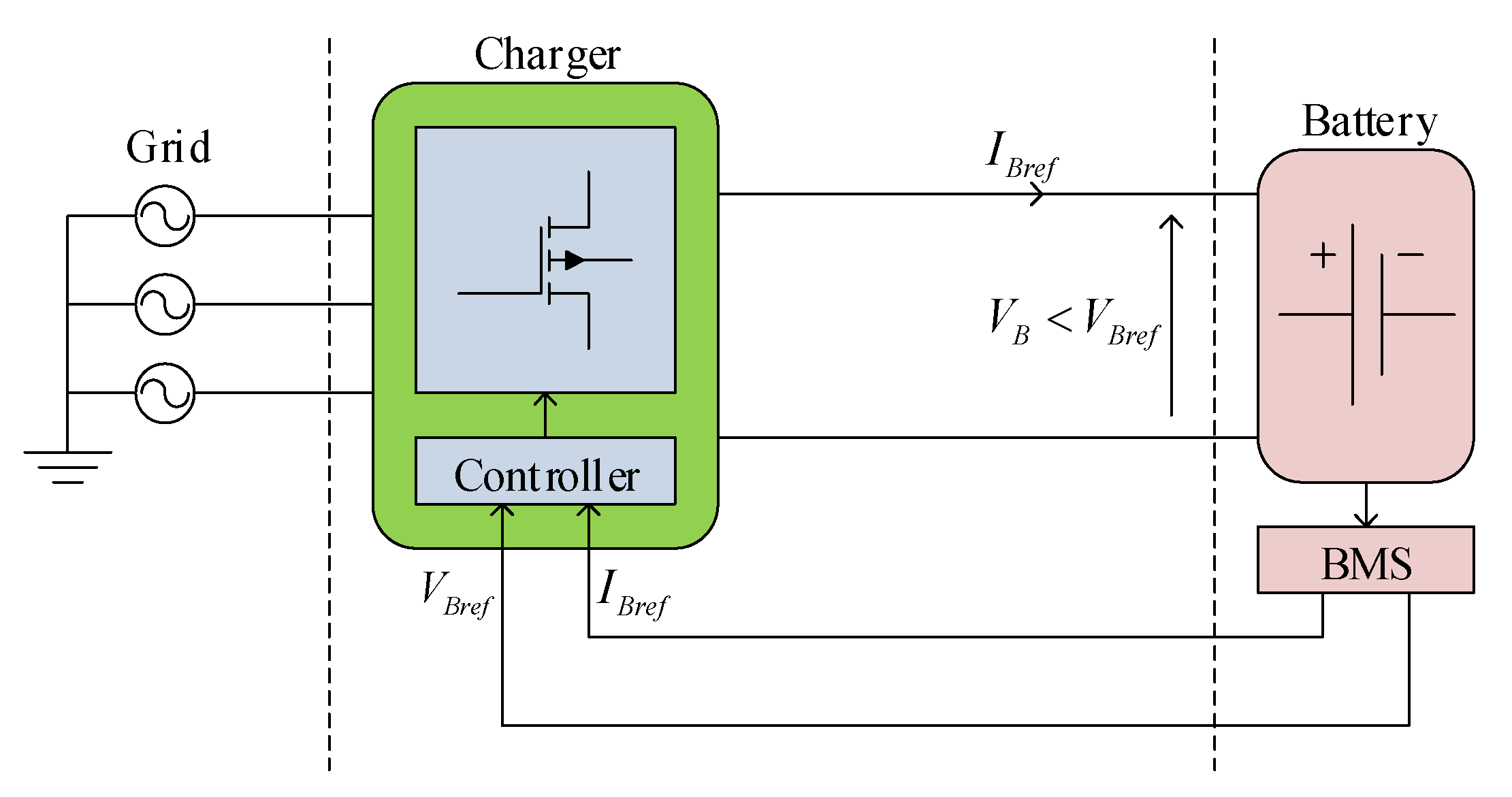
Figure 2.
Ultra-fast charging system.
2. Different Power Electronic Topologies of Ultra-Fast Charger
To design a universal ultra-fast charger (adapted to different grid voltages and different battery voltages), two stages are required. As shown in Figure 3, the first stage ensures the AC-DC conversion and guarantees a unity power factor. The second stage provides DC-DC conversion and adapts the voltage of the ultra-fast charger to the voltage of the battery. This voltage varies according to the state of charge of the battery. The second stage is galvanically isolated using a transformer for safety purposes. If galvanic isolation is ensured by the MV/LV transformer, a non-isolated DC-DC converter can be employed [9][7].
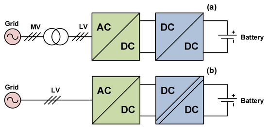
Figure 3. Structural scheme of the ultra-fast charging systems: (a) ultra-fast charging station with a non-isolated DC/DC converter; (b) ultra-fast charging station with an isolated DC/DC converter.
2.1. AC-DC Power Converters
At the AC-DC stage, the three-phase two-level rectifier, NPC converter, and Vienna rectifier are widely used for off-board ultra-fast charging [29][8]. They are well-developed converters, the characteristics of which are suitable for the electric vehicle charging industry.
As shown in Figure 54a, the three-phase two-level rectifier (3θ-2L) consists of six controlled switches. This power converter generates low total harmonic current distortion, provides bidirectional power flow, and achieves a power factor close to unity, with good efficiency and easy control [11][9]. However, a bulky filter inductor is required in this rectifier compared to the other three-level topologies to regulate THDi to low values [30][10].
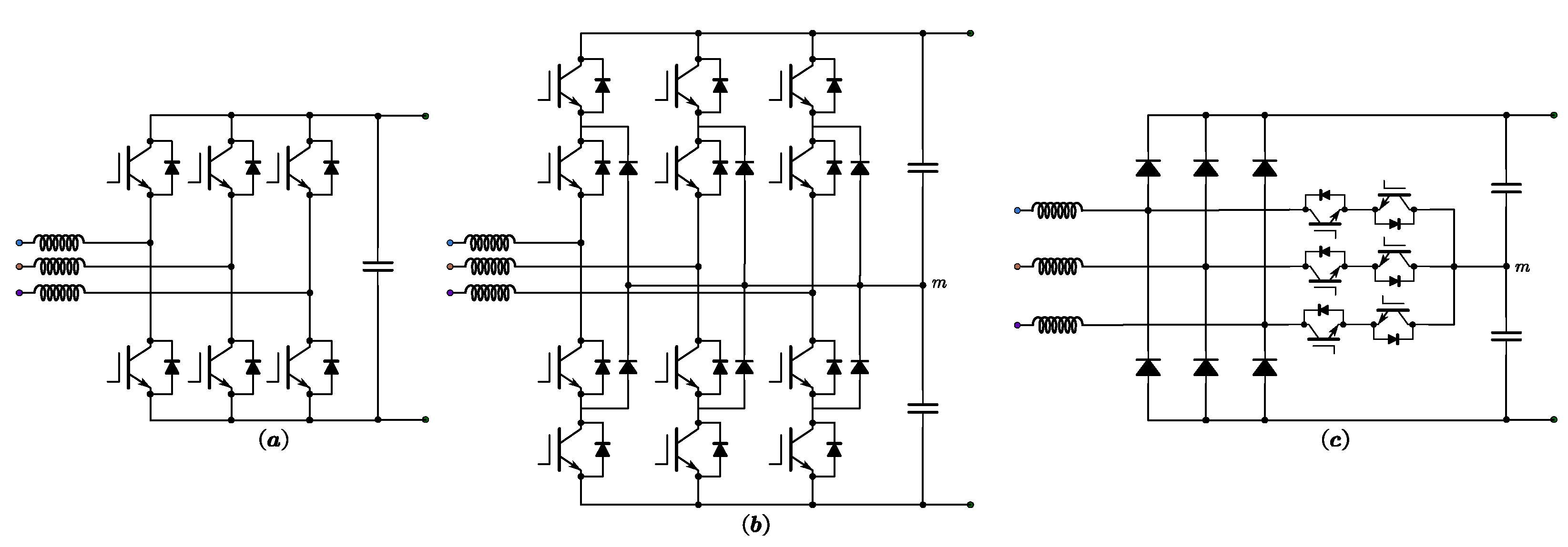
Figure 54. DC-AC converter topologies for electric vehicle ultra-fast charging application: (a) three-phase two-level rectifier; (b) NPC converter; (c) Vienna rectifier.
Figure 54b shows the three-phase three-level neutral point clamped (NPC) converter, which has 12 controlled switches and six parallel diodes and offers bidirectional power flow. The NPC topology has a lower total harmonic distortion, which can further reduce the filter inductor [31][11]. Moreover, this topology offers a bipolar DC bus, enabling two DC-DC converters cascaded to be connected in series-series or series-parallel configuration [32[12][13],33], which can increase the output power of the charging systems. However, this topology requires a higher number of power semiconductors, resulting in a higher cost. Another drawback of the NPC is the complexity of the control system [30][10].
Since ultra-fast chargers are designed for occasional charging with an electric vehicle plugged in only during the period of the charge, bidirectional energy flow is considered unnecessary. Hence, the Vienna rectifier is the best solution. This three-level converter illustrated in Figure 54c offers a power factor close to unity, lower total harmonic current distortion, high-power density, and good economics, thanks to the reduced number of controlled switches [34][14].
Table 1 shows a comparison of the previously discussed DC-AC converter topologies using the most popular simulation environments for power electronics (PSIM, PLECS/SpeedFit, and MATLAB/Simulink). According to this comparison, the Vienna rectifier is the best AC-DC converter due to its high quality of output voltages and input currents, and best efficiency with low cost. However, the emergence of photovoltaic systems and storage batteries at charging stations requires bidirectional rectifiers [35][15]. Therefore, the NPC converter is the best alternative.
Table 1.
Comparison table for DC-AC converter topologies.
| Ref. | Simulation Software | Simulation Parameters | Performance and Quality | Topology | ||||||||
|---|---|---|---|---|---|---|---|---|---|---|---|---|
| Topology of Converter | Voltage Ripple (V) | Current Ripple (A) | Efficiency (%) | |||||||||||||||
|---|---|---|---|---|---|---|---|---|---|---|---|---|---|---|---|---|---|---|
| Output Power P (kW) |
Input Voltage V | AC | (V) | Output Voltage V | dc | (V) | Switching Frequency f | sw | (kHz) | Inductor L (µH) |
Capacitor C | 1 | /C | 2 | (µF) | 3θ-2L | NPC | Vienna |
| [19][16] | PSIM | 50 | 400 | 800 | 100 | 500 | 3000 | Performance | Efficiency (%) | 97.87 | 96.20 | 97.14 | ||||||
| Traditional DC-DC buck | 1.084 × 10⁻² | 1.196 | 98.99 | |||||||||||||||
| Total losses (W) | 1062 | 1896 | 1428 | |||||||||||||||
| Input quality |
PF (%) | 99.933 | 99.992 | 99.992 | ||||||||||||||
| THD | ||||||||||||||||||
| Two-phase interleaved DC-DC buck | 6.909 × 10i (%) | 4.04 | 1.27 | 1.25 | ||||||||||||||
| −6 | 6.521 × 10 | −6 | 99.13 | DPF | 1 | 1 | 1 | |||||||||||
| Output quality | Low voltage ripple (V) | 3.40 | 4.81 | 1.99 | ||||||||||||||
| Capacitor currents (A) | 43.6 | 47.1 | 42.7 | |||||||||||||||
| [36][17] | PLECS | 22 | 400 | 800 | 20 | 750 | - | Performance | Efficiency (%) | 98.86 | 98.44 | 98.95 | ||||||
| Total losses (W) | 256.48 | 351.81 | 237.16 | |||||||||||||||
| Costs (USD) | 343.34 | 456.76 | 385.8 | |||||||||||||||
| [37][18] | MATLAB | 2 | 50 | 200 | 15 | 300 | 9020 | Input quality |
PF (%) | - | 99.958 | 99.981 | ||||||
| THDi (%) | - | 2.87 | 1.94 | |||||||||||||||
| DPF | - | 1 | 1 | |||||||||||||||
2.2. DC-DC Power Converters
The adaptation of the output voltage of the AC-DC converter to the battery voltage is achieved by the second stage: the DC-DC converter. This stage is accountable for charging the battery electric vehicle, according to a specific charging method, while ensuring safe operation of the battery by communicating with the BMS.
If galvanic isolation is ensured by the power transformer, a non-isolated DC-DC converter can be employed as a second stage. Figure 65 shows a charging station with three ultra-fast chargers, each with a power of 350 kW, with galvanic isolation provided by a MV/LV transformer with a power of 1250 kVA.
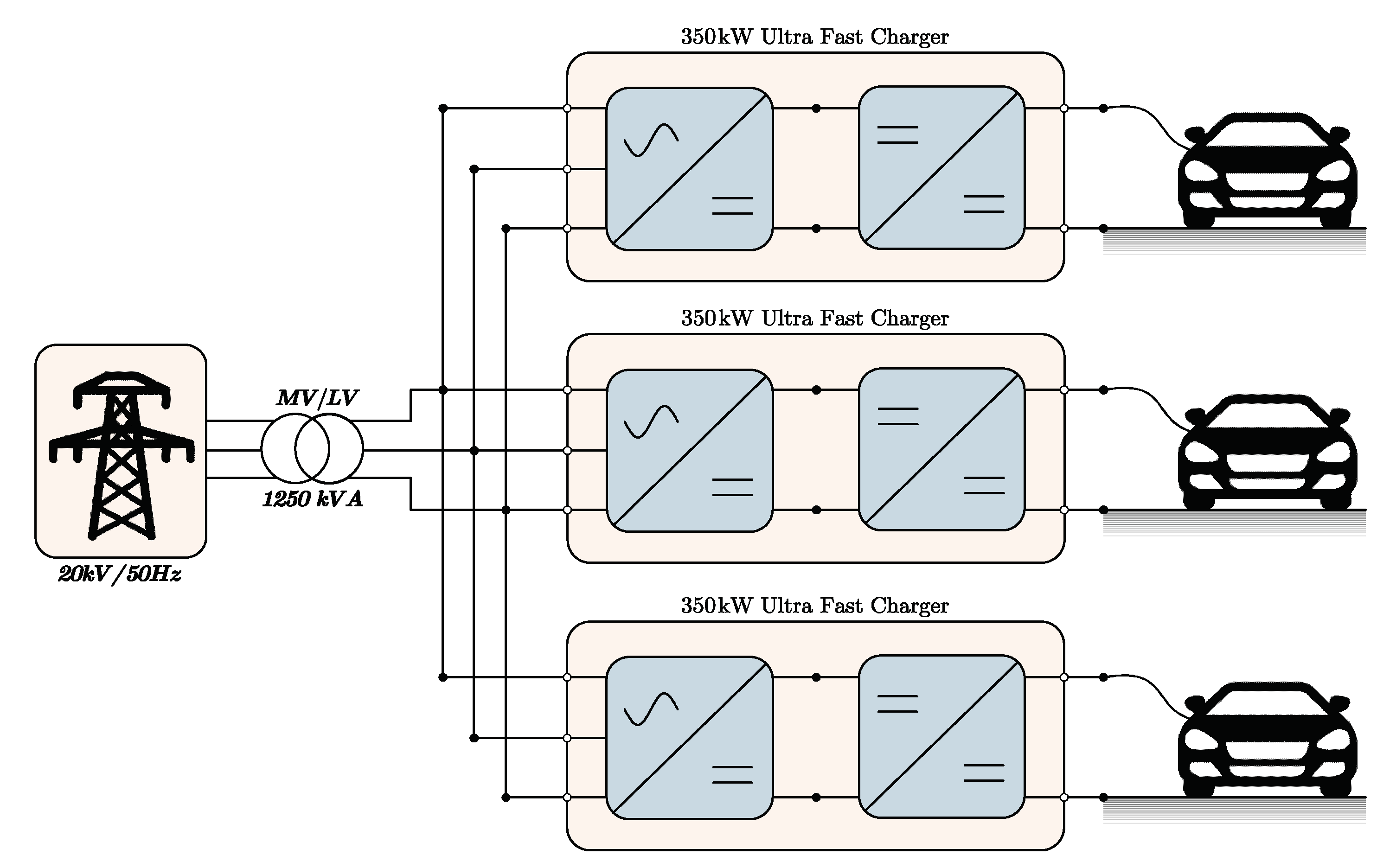
Figure 65.
Three ultra-fast chargers isolated by a MV/LV transformer.
As the battery voltage is less than the output voltage of the rectifier in many applications, the Buck converter illustrated in Figure 76a can be used to decrease the input voltage, but this is not practical for high power applications because the current is transported by a unique switch [38][19]. In addition, the size of the filtering inductor will be high if low current ripple is desired [39][20].
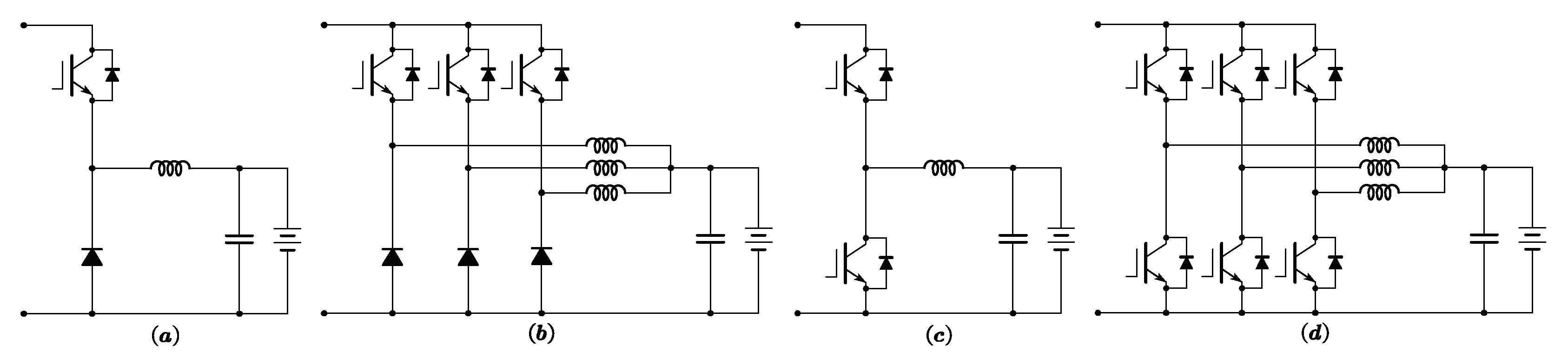
Figure 76. Non-isolated DC-DC converter topologies for electric vehicle ultra-fast charging application: (a) buck DC-DC converter; (b) three-phase interleaved DC-DC buck converter; (c) buck-boost DC-DC converter; (d) three-phase interleaved DC-DC buck-boost converter.
As an alternative to using an oversized single-phase converter, three-phase interleaved DC-DC buck converters are suitable for high-current applications thanks to their ability of sharing the output current between three phases, allowing the reduction in lower filtering inductors and smaller semiconductor switches. In addition, the efficiency of the power converter is generally higher because the fundamental frequency is multiplied by three, which results in a high frequency of the system, a better transient response, a low current ripple, and a reduced size of output filters [40][21]. As presented in Figure 76b, the three-phase interleaved DC-DC buck converter has a simple structure. Hence, this converter has been well explored in the literature for electric vehicle charging applications [41,42][22][23]. Nevertheless, as the number of phases grows, the number of power interrupters, cost, difficulty of the control system, and power density also grow [43][24].
If bidirectional power flow is needed, and the power exchange is requested between the electric vehicle storage device and the grid (V2G), the buck-boost converters illustrated in Figure 76c,d can be used for charging stations [44][25].
A comparative study of non-isolated DC-DC converters is presented in Table 2. As can be noticed, the voltage ripple of the two-phase interleaved DC-DC buck converter is low compared to the classical buck converter. Thus, the interleaved converters reduce the voltage ripple, which can increase the battery lifetime in an electric vehicle. Similar to the voltage ripple, the current ripple can be reduced if the interleaved converter is employed. This can improve the efficiency of battery charging and reduce the size of the filtering inductor [45][26].
Table 2.
Comparison table for non-isolated DC-DC converter topologies.
If the ultra-fast charger is plugged directly to the LV grid, a galvanic isolation is required to ensure operational safety rules. Hence, a DC-DC converter is galvanically isolated using a transformer.
Figure 87a depicts the basic topology of the Phase-Shift Full Bridge (PSFB) converter. It consists of an H-Bridge with power switches in the primary of the transformer, and usually a diode bridge in the secondary connected to the battery electric vehicle. For this reason, this converter provides only unidirectional power transfer [46][27]. It is possible to perform zero-current switching (ZCS) or zero-voltage switching (ZVS). Hence, the PSFB converters can deliver a very high-power rating and high output voltage [47][28].
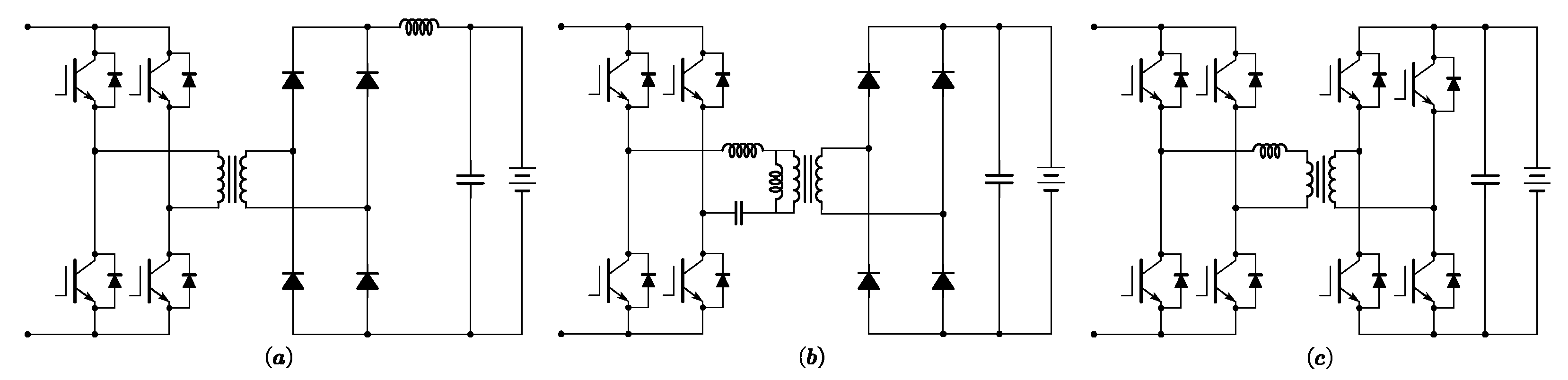
Figure 87. Isolated DC-DC converter configurations for electric vehicle ultra-fast charging application: (a) Phase-Shift Full Bridge (PSFB) converter; (b) LLC resonant converter; (c) Dual Active Bridge (DAB) converter.
The LLC resonant converter, as depicted in Figure 87b, has a resonant LLC tank, which consists of a resonant capacitor, a resonant inductor, and the magnetizing inductance of the high-frequency transformer. This isolated converter provides excellent efficiency and a high-power density and is widely used for ultra-fast charging [48][29]. The soft-switching techniques are also employed, whether ZVS turn-on or ZCS turn-off [49][30].
The work developed in [50][31] provides a comparative study between the LLC resonant converter and the PSFB converter during total charging and the CC-CV charging process of the battery. Table 3 shows that the PSFB converter is the best isolated DC-DC converter thanks to its low losses, good efficiency, and low cost.
Table 3.
Comparison table for LLC resonant converter and PSFB converter.
| Topology of Converter | PSFB | LLC |
|---|---|---|
| Efficiency (30% < SOC < 95%) | 94.43% | 94.20% |
| Losses (30% < SOC < 95%) | 118 W | 127 W |
| Frequency | 100 kHz | 100 kHz |
| Output filter capacitance | 200 µF | 1500 µF |
| Output filter inductance | 10 µH | - |
| Resonant capacitance | - | 54.5 nF |
| Resonant inductance | - | 46.6 µH |
If bidirectional energy flow is needed, a Dual Active Bridge (DAB) converter, as illustrated in Figure 87c, can be employed for electric vehicle charging systems. However, the control of the eight power switches is more complex, and the non-resonant operation results in a slightly lower efficiency at lower power [51][32].
2.3. Industrial Applications
As seen in Figure 98, the modular 50 kW power cell designed by Semikron has an input Vienna rectifier and a PSFB converter for an output voltage up 1000 V. It is developed for easy paralleling to meet 350 kW and make it possible to recharge an electric vehicle in 11 min [52][33]. Figure 109 shows an example of the topology proposed by Infineon Technologies for a 30 kW converter to be combined for the realization of a unidirectional very high power charger. This charger consists of a Vienna rectifier followed by an LLC resonant converter [53][34]. Another example based on a three-phase two-level rectifier and three-phase interleaved DC-DC buck-boost power converter is illustrated in Figure 110, where ABB’s Terra High Power Series is used. These fast chargers achieve 150 kW by the unit, while each unit is composed of 50 kW modules, with galvanic isolation ensured by a power transformer. To achieve increased power levels, this unit is multiplied many times to attain a maximum of 600 kW for electric trucks and electric buses [54][35].
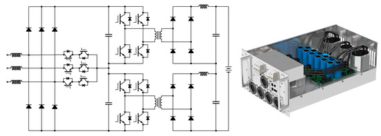
Figure 98.
Modular 50 kW power cell (Designed by Semikron).
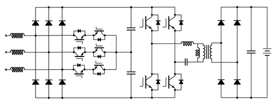
Figure 109.
Modular 30 kW charger (proposed by Infineon Technologies).
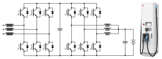
Figure 110.
Modular 50 kW charger (designed by ABB).
References
- Cho, I.-H.; Lee, P.-Y.; Kim, J.-H. Analysis of the Effect of the Variable Charging Current Control Method on Cycle Life of Li-ion Batteries. Energies 2019, 12, 3023.
- Suarez, C.; Martinez, W. Fast and Ultra-Fast Charging for Battery Electric Vehicles—A Review. In Proceedings of the 2019 IEEE Energy Conversion Congress and Exposition (ECCE), Baltimore, MA, USA, 29 September–3 October 2019.
- Tomaszewska, A.; Chu, Z.; Feng, X.; O’Kane, S.; Liu, X.; Chen, J.; Ji, C.; Endler, E.; Li, R.; Liu, L.; et al. Lithium-ion battery fast charging: A review. eTransportation 2019, 1, 100011.
- Liu, K.; Li, K.; Peng, Q.; Zhang, C. A brief review on key technologies in the battery management system of electric vehicles. Front. Mech. Eng. 2018, 14, 47–64.
- Yazami, R. Revolutionizing the Battery Charging Technologies. In Proceedings of the International Battery Seminar, Orlando, FL, USA, 20–23 March 2021.
- Gabbar, H.A.; Othman, A.; Abdussami, M.R. Review of Battery Management Systems (BMS) Development and Industrial Standards. Technologies 2021, 9, 28.
- Rajendran, G.; Vaithilingam, C.; Misron, N.; Naidu, K.; Ahmed, M.R. A comprehensive review on system architecture and international standards for electric vehicle charging stations. J. Energy Storage 2021, 42, 103099.
- Rubino, L.; Capasso, C.; Veneri, O. Review on plug-in electric vehicle charging architectures integrated with distributed energy sources for sustainable mobility. Appl. Energy 2017, 207, 438–464.
- Tu, H.; Feng, H.; Srdic, S.; Lukic, S. Extreme Fast Charging of Electric Vehicles: A Technology Overview. IEEE Trans. Transp. Electrif. 2019, 5, 861–878.
- Barth, C.B.; Foulkes, T.; Azofeifa, O.; Colmenares, J.; Coulson, K.; Miljkovic, N.; Pilawa-Podgurski, R.C. Design, Operation, and Loss Characterization of a 1-kW GaN-Based Three-Level Converter at Cryogenic Temperatures. IEEE Trans. Power Electron. 2020, 35, 12040–12052.
- Ramakrishnan, H.; Rangaraju, J. Power Topology Considerations for Electric Vehicle Charging Stations. Application Report. Tex. Instrum. 2020. Available online: https://www.ti.com/lit/an/slla497/slla497.pdf (accessed on 27 May 2022).
- Deb, N.; Singh, R.; Brooks, R.; Bai, K. A Review of Extremely Fast Charging Stations for Electric Vehicles. Energies 2021, 14, 7566.
- Tan, L.; Wu, B.; Yaramasu, V.; Rivera, S.; Guo, X. Effective Voltage Balance Control for Bipolar-DC-Bus-Fed EV Charging Station with Three-Level DC–DC Fast Charger. IEEE Trans. Ind. Electron. 2016, 63, 4031–4041.
- Yan, X.; Qin, F.; Jia, J.; Zhang, Z.; Li, X.; Sun, Y. Virtual synchronous motor based-control of Vienna rectifier. Energy Rep. 2020, 6, 953–963.
- Juton, A.; Rain, X.; Sauvant-Moynot, V.; Orsini, F.; Saber, C.; Bacha, S.; Bethoux, O.; Labouré, É. The Technologies of Electric Vehicles; Dunod: Paris, France, 2021; pp. 168–169.
- Aretxabaleta, I.; De Alegría, I.; Andreu, J.; Kortabarria, I.; Robles, E. High-Voltage Stations for Electric Vehicle Fast-Charging: Trends, Standards, Charging Modes and Comparison of Unity Power-Factor Rectifiers. IEEE Access 2021, 9, 102177–102194.
- Cuma, M.U.; Savrun, M.M. Performance Benchmarking of Active-Front-End Rectifier Topologies Used in High-Power, High-Voltage Onboard EV Chargers. Cukurova Univ. J. Fac. Eng. 2021, 36, 1041–1050.
- Luqman, M.; Yao, G.; Zhou, L.; Zhang, T.; Lamichhane, A. A Novel Hybrid Converter Proposed for Multi-MW Wind Generator for Offshore Applications. Energies 2019, 12, 4167.
- Dusmez, S.; Cook, A.; Khaligh, A. Comprehensive Analysis of High Quality Power Converters for Level 3 Off-Board Chargers. In Proceedings of the 2011 IEEE Vehicle Power and Propulsion Conference, Chicago, IL, USA, 6–9 September 2011; pp. 1–10.
- PARISI, Carmen. Multiphase buck design from start to finish (Part 1). Texas Instruments, Application Report SLVA882. 2017. Available online: https://www.ti.com/lit/an/slva882b/slva882b.pdf (accessed on 8 July 2022).
- Wang, J.; Peng, R.; Cai, C.; Yu, H.; Chen, M.; Liu, Y.; Wu, K.; Tang, S.; Wei, H.; Chen, J. An Efficiency Optimization Control Method for Three-Phase Interleaved DC-DC Converter. In Proceedings of the 2021 3rd Asia Energy and Electrical Engineering Symposium (AEEES), Chengdu, China, 26–29 March 2021; pp. 285–289.
- Choi, H.; Kim, S.; Kim, J.; Cho, Y.; Lee, K. Deadbeat predictive direct power control of interleaved buck converter-based fast battery chargers for electric vehicles. J. Power Electron. 2020, 20, 1162–1171.
- Pinto, J.; Monteiro, V.; Exposto, B.; Barros, L.; Sousa, T.; Monteiro, L.; Afonso, J. Power Electronics Converters for an Electric Vehicle Fast Charging Station with Storage Capability. In Proceedings of the International Conference on Green Energy and Networking, Barcelona, Spain, 25–27 April 2018; pp. 119–130.
- Alharbi, M.; Dahidah, M.; Pickert, V.; Yu, J. Comparison of SiC-based DC-DC modular converters for EV fast DC chargers. In Proceedings of the 2019 IEEE International Conference on Industrial Technology (ICIT), Melbourne, Australia, 13–15 February 2019; pp. 1681–1688.
- Rachid, A.; El Fadil, H.; Gaouzi, K.; Belhaj, F. Output Feedback Control of Bidirectional dc-dc Power Converter for BEV Charger. In Proceeding of the 4th International Conference on Automation, Control Engineering and Computer Science (ACECS), Hammamet, Tunisia, 20–22 March 2017; Volume 19, pp. 46–51.
- Murugappan, K.; Seyezhai, R.; Kishor Sabarish, G.; Kaashyap, N.; Jason Ranjit, J. Simulation and Analysis of Interleaved Buck DC-DC Converter for EV Charging. In Advances in Smart Grid Technology. Lecture Notes in Electrical Engineering; Siano, P., Jamuna, K., Eds.; Springer: Berlin/Heidelberg, Germany, 2020; Volume 687.
- Habib, S.; Khan, M.M.; Abbas, F.; Ali, A.; Faiz, M.T.; Ehsan, F.; Tang, H. Contemporary trends in power electronics converters for charging solutions of electric vehicles. CSEE J. Power Energy Syst. 2020, 6, 911–929.
- Hassanzadeh, N.; Yazdani, F.; Haghbin, S.; Thiringer, T. Design of a 50 kW Phase-Shifted Full-Bridge Converter Used for Fast Charging Applications. In Proceedings of the 2017 IEEE Vehicle Power and Propulsion Conference (VPPC), Belfort, France, 11–14 October 2017.
- Safayatullah, M.; Elrais, M.; Ghosh, S.; Rezaii, R.; Batarseh, I. A Comprehensive Review of Power Converter Topologies and Control Methods for Electric Vehicle Fast Charging Applications. IEEE Access 2022, 10, 40753–40793.
- Town, G.; Taghizadeh, S.; Deilami, S. Review of Fast Charging for Electrified Transport: Demand, Technology, Systems, and Planning. Energies 2022, 15, 1276.
- Campanini, A.; Simonazzi, M.; Bosi, M.; Rossi, C. Design and Comparison Between PSFB and LLC 400/48V DC/DC Stage for On-Board Battery Charger During Total and Partial CC-CV Charging Cycles. In Proceedings of the 2022 IEEE 21st Mediterranean Electrotechnical Conference (MELECON), Palermo, Italy, 14–16 June 2022; pp. 1102–1106.
- Alatai, S.; Salem, M.; Ishak, D.; Das, H.S.; Alhuyi Nazari, M.; Bughneda, A.; Kamarol, M. A Review on State-of-the-Art Power Converters: Bidirectional, Resonant, Multilevel Converters and Their Derivatives. Appl. Sci. 2021, 11, 10172.
- Kalkmann, B.; Gassauer, T. Novel approach of power electronics for efficient DC fast charging systems. In Proceedings of the PCIM Asia 2018; International Exhibition and Conference for Power Electronics, Intelligent Motion, Renewable Energy and Energy Management, Shangai, China, 26–28 June 2018.
- Harmon, O.; Di Domenico, F.; Raghunath, S. Implementing Fast DC BEV Chargers Up to 150 kW. Infineon Technol. 2019. Available online: https://www.infineon.com/dgdl/Infineon-Implementing_Fast_DC_BEV_Chargers-Article-v01_00-EN.pdf (accessed on 3 August 2022).
- Rivera, S.; Kouro, S.; Vazquez, S.; Goetz, S.; Lizana, R.; Romero-Cadaval, E. Electric Vehicle Charging Infrastructure: From Grid to Battery. IEEE Ind. Electron. Mag. 2021, 15, 37–51.
More