Your browser does not fully support modern features. Please upgrade for a smoother experience.
Please note this is a comparison between Version 1 by Asmaa Hameed Majeed and Version 2 by Rita Xu.
Due to the fact that the quality of the received signal is adversely affected by the beam squint phenomenon, which is especially pertinent to the millimeter wave (mmwave) bands, many studies have been utilised by other researchers to provide light on some of the challenges that come with analysing this type of occurrence. Squint causes several issues, the most important of which are its detrimental effects on gain, line of sight, angle of arrival, progressive phase, usable bandwidth, and fading effect. As a result of these obstacles, the advantages of adopting a high-frequency band such as mmwave in modern wireless communication systems are severely limited.
- beam squinting
- massive MIMO
- millimeter waves
1. Introduction
In today’s world, almost everyone has a mobile device, and the number of people who do is growing. Concurrently, the number of interactive multimedia apps is also growing, and experts predict that this pattern will continue into the foreseeable future [1]. In spite of the fact that mobile technologies of the first, second, third, and fourth generations have spent the last 25 years working to increase the speed and efficiency of wireless networks, there are still some specific application areas in which current wireless networks are unable to deliver [2]. As the need for mobile traffic steadily develops, a bottleneck between spectrum constraints and capacity requirements is becoming more obvious. This bottleneck is becoming more and more apparent. The wireless bandwidth bottleneck is one of the most serious challenges faced by 5G communications [3]. Wireless carriers need to be ready to sustain a growth in total mobile traffic that may be as much as 1000 times higher than it is now since the need for capacity in mobile broadband communications is growing at a substantial rate each year. The pursuit of inventive solutions is required in order to make the transition to the fifth generation (5G) of wireless technology [4]. Because of the growing need for bandwidth, the millimetre wave spectrum has been standardised for use in high-speed wireless communication [5]. mmwaves are an interesting possibility since they have a significant amount of bandwidth and spectrum that is readily available (approximately 60 GHz) [6]. mmwave communications may make use of the large capacity that is now being underutilised, which will help them fulfil the high demands of the future generation of wireless networks [7].
Although the potential bandwidth of mmwave frequencies is promising, the propagation characteristics of these frequencies are very different from those of microwave frequency bands [8]. These propagation characteristics include path loss, diffraction and blockage, rain attenuation, air absorption, and foliage loss behaviours. The massive multiple-input multiple-output (MIMO) technology is a potential answer to this problem. With this technology, a considerable number of antennas might provide sufficient gain to compensate for the route loss [9][10][9,10]. Massive MIMO over mmwaves is a novel approach that combines the benefits of massive MIMO antenna arrays with the vast amount of bandwidth that is currently accessible over mmwaves [11]. Massive MIMO over mmwaves has the potential to revolutionise wireless communication. Beam squint is one of the issues that arise in mmwave communications. This issue manifests itself as a change in the spatial direction of a beam as a function of frequency. As a consequence, there are discernible variations in the path phases at various frequencies.
2. Broadband Communication
2.1. Millimeter Waves and Massive MIMO
In order to attain more bandwidth than traditional frequency bands, 5G and the following 6G mobile networks operate in high-frequency zones [12]. This allows for high-capacity wireless transmission of data at speeds up to several gigabits per second (Gbps) [13]. It is generally agreed that mmwave communication [14] is one of the most crucial technologies for reaching peak data rates of 10 Gbit/s [15]. This is due to the fact that increasing the bandwidth is an effective method for increasing the system’s capacity [7] and that there is a lot of bandwidth available in the mmwave channels. Measurement and modeling of mmwave channels [16] and assessment of the band’s potential for future wireless systems have received significant academic and industrial attention because of the spectrum’s abundance [17]. However, due to negative propagation effects, particularly those brought on by obstructions in the line of sight (LoS), these high frequencies have been used only sparingly up to this point [18]. It is important to handle the greater propagation losses associated with mmwave frequencies, especially beyond 100 m and in non-line of sight (NLoS) environments [19]. On the one hand, signal transmission becomes more difficult in areas with dense foliage and higher propagation loss [20]. Nonetheless, the link could be forced into the low signal-to-noise ratio (SNR) zone due to the constrained send signal power dispersed over a broad bandwidth [21]. To address these problems, several transceiver topologies have been created that steer the received or broadcast beams in the appropriate direction. [22]. The two main technologies that will enable 5G mmwave communication are MIMO and beamforming [23]. Beamforming is a method for using MIMO/array elements to direct the main lobe radiation beam at the transmitters and receivers in the desired directions, eliminating the undesirable spatial selectivity [24]. The beamforming array is widely divided into the following categories: analog, digital, and hybrid beamforming array [25]. Figure 1 shows the block diagram of massive MIMO system.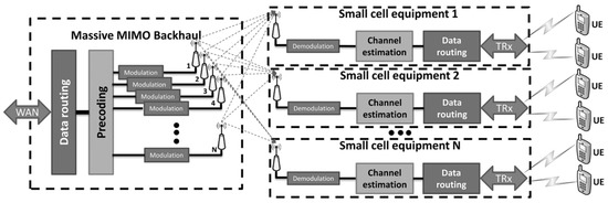
2.1.1. Analog Beamforming
The architecture of analog beamforming is shown in Figure 2. A phased array is used to accomplish analog beamforming, and the single RF chain is powered by either an analog-to-digital converter (ADC) in the receiver or a digital-to-analog converter (DAC) in the transmitter. Frequency-up converters, power amplifiers, and other components form a transmitter’s RF chain; low-noise amplifiers, frequency-down converters, and other components form a receiver’s RF chain [27]. The phased array’s antenna weights are required to be digitally controllable phase changes. The relative amplitudes of the signal sent into the antennas of the transmitter cannot be adjusted, and the phases of the phase shifters are normally quantized to low resolution [28]. A beam is created as a result of the send signal, which is constructive in certain directions and destructive in others. On the basis of precise beam-steering tactics, the phase shifters’ phases can be dynamically changed. The receiver has a similar set of features [27].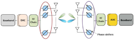
2.1.2. Digital Beamforming
The radio frequency (RF) signal in a digital array is transformed into a digital signal at the sub-array or element level, and beamforming is accomplished using a digital signal processor [30]. In order to process the control signals for beamforming, a digital signal processor is used, which offers additional flexibility and degrees of freedom for the implementation of effective beamforming algorithms. Due to the method’s requirement for a separate RF chain for each antenna element, it consumes a great deal of power and has a complicated architecture [31]. Figure 3 shows the structure of digital beamforming.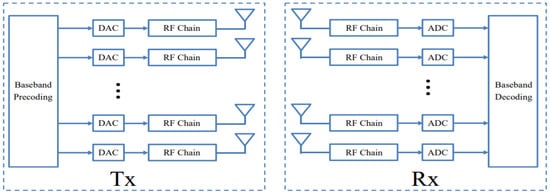
2.1.3. Hybrid Beamforming
Recently, interest in the hybrid analog/digital beamforming array has increased [32][33][32,33]. This type of array increases the efficiency of analog beamforming while reducing the complexity of digital beamforming [34]. The hybrid beamformer is composed of two parts: an analog and a digital component [35]. The RF chains that compose the digital portion share a common structure with the many plans under discussion. For each user on each subcarrier, a hybrid beamforming’s digital component can be used, just like in traditional fully digital beamforming. In contrast, this is not true of the hybrid beamforming analog network or analog component. Since the transmitted signals for all users are combined by the digital beamformers and analog RF beamforming is a post-IFFT (inverse Fast Fourier Transform) operation, all users and subcarriers in an analog network share the same RF component [36]. Hybrid beamforming’s fundamental architecture is depicted in Figure 4.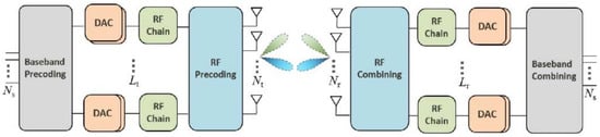
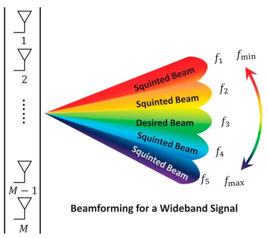
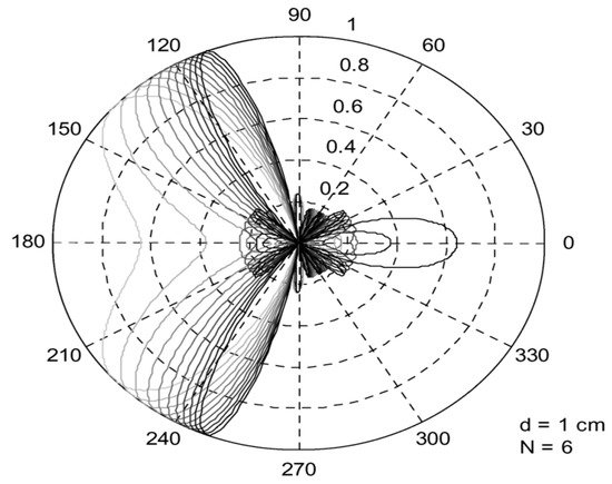
Figure 6. Beam squint effect for a phased array antenna using electrical phase shifters operating at frequencies in the range of 10–20 GHz [39].
2.2. Effect of Beam Squint on the Communication System Performance
-
Bandwidth and Capacity:
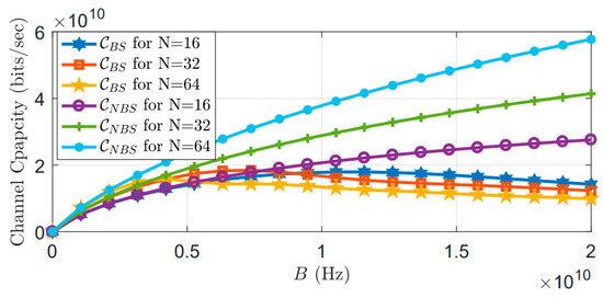
Figure 7. Capacity as a function of bandwidth with beam squint (CBS) and without beam squint (CNBS) [41].
-
Channel estimation:
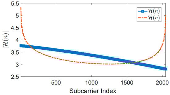
Figure 8. Example of MLE channel estimate using the receiver’s beam squint. There is no beam squint in the transmitter and only one path. No more noise exists. The number of antennas N = 16 [41].