Your browser does not fully support modern features. Please upgrade for a smoother experience.
Please note this is a comparison between Version 2 by Rita Xu and Version 1 by LAV KUMAR KAUSHIK.
Clean and efficient cook-stoves and fuels are essential to address energy demand and ensure safe cooking for billions of people across the globe. Currently, nearly 2651 million people in developing countries (Africa—910 million, Asia—1674 million, Central and South America—57 million, and Middle East—10 million) are without clean cooking facilities.
- liquid and gaseous fuels
- clean cooking stoves
- emerging cooking technology
1. Introduction
In the previous decades, there was not much difference in the cooking technologies and the fuels used between the rural and urban households. However, due to improved living standards, sophisticated lifestyles, access to technology, and the availability of more resources to the urban people, a greater change in cooking technologies and availability of fuels has taken place between the urban and rural communities. For instance, while urban households started using cooking fuels such as natural gas, Liquefied Petroleum Gas (LPG), kerosene, biogas, and electricity, the people living in rural areas are still using traditional cooking fuels such as firewood, dried cow-dung cakes, dried leaves, and plant residues. Significant variations in access to clean cooking between urban and rural areas has led to disparities in infrastructure and the availability of clean fuels and technologies [2][1]. There is an increasing trend of the adoption of gaseous (LPG, natural gas, and biogas) and liquid fuels (kerosene, methanol, ethanol, etc.) in low and middle-income countries [3][2]. This is growing rapidly due to the global initiatives to promote clean energy cooking fuels [4,5,6][3][4][5]. Though electric stoves are pollution free at a household level, they may not be feasible for the developing nations such as India to adopt for cooking applications in the next few decades due to the rapid increase in electrical demand for the industrial and agricultural sectors. Further, some parts of the rural population in India still lack a consistent power supply, and a few villages even lack access to electricity. Major parts of the electricity generated in India is through coal, and the country is still on its way to shift towards renewable sources for electricity production. There is also a lack of an adequate supply of coal, which makes the generation of electricity inconsistent. Thus, shifting from gas stoves to electric stoves would only add a burden to the government.
Almost four million deaths per year have been reported due to pollutants released from the burning of kerosene, charcoal, wood, etc., for cooking [7][6]. Exposure to pollutants from cooking with such fuels can lead to chronic obstructive pulmonary disorder, heart disease, childhood pneumonia, lung cancer, etc. [8][7]. Among the 17 Sustainable Development Goals (SDG) of the United Nations (UN), providing access to clean cooking solutions has been given top priority in SDG 7 [2][1]. Electricity from renewable energy sources with electrical cooktops can be conceptualized as a possible solution; however, recent multi-model analyses [9,10,11,12,13,14][8][9][10][11][12][13] in various countries have shown the complexity of cooking fuel transition and questioned its feasibility in the diverse populations of developing countries. The potential economic and human health benefits of the transition to cleaner cooking technologies and fuels have motivated many researchers to focus on improved cook-stoves [15][14]. Previously, people used to construct chimneys to vent out the emissions from the kitchen. However, since the emissions were directly released into the atmosphere, this practice created outdoor pollution, and hence they have slowly moved towards the usage of clean cooking fuels [16][15].
2. Operating Principles of Gaseous Fuel-Based Cook-Stoves
Based on the stage of fuel and air mixing, burners of gaseous fuel cook-stoves are mainly classified as aerated and non-aerated; the fuel and air will be premixed in the former, while they interact only at the reaction zone in the latter. In most aerated burners used in domestic cook-stoves, additional air is supplied to ensure cleaner combustion. These burners have been developed to overcome the shortcomings of non-aerated burners, such as unstable combustion and high manufacturing costs [21][16]. The cook-stove burners can also be classified according to the mode of air supply as forced-draft (air is supplied externally) and natural draft or self-aspirated (air is induced naturally). The phenomenon of the natural induction of air in a typical self-aspirated burner is shown in Figure 1.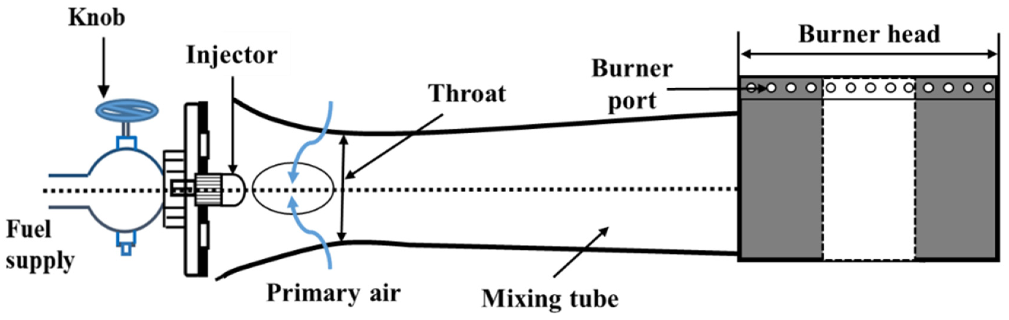
Figure 1. Phenomenon of the natural induction of air in a typical self-aspirated burner.
2.1. Cook-Stoves with Bunsen Burner Principle
In Bunsen burner-based cook-stoves, the fuel–air mixture is delivered through radial ports on the burner head. They operate on the mechanism of Free Flame Combustion (FFC), in which the occurrence of combustion of fuel–air mixture is above the top surface of the burner head, and the burnt products depart through the downstream section of the flame (Figure 2).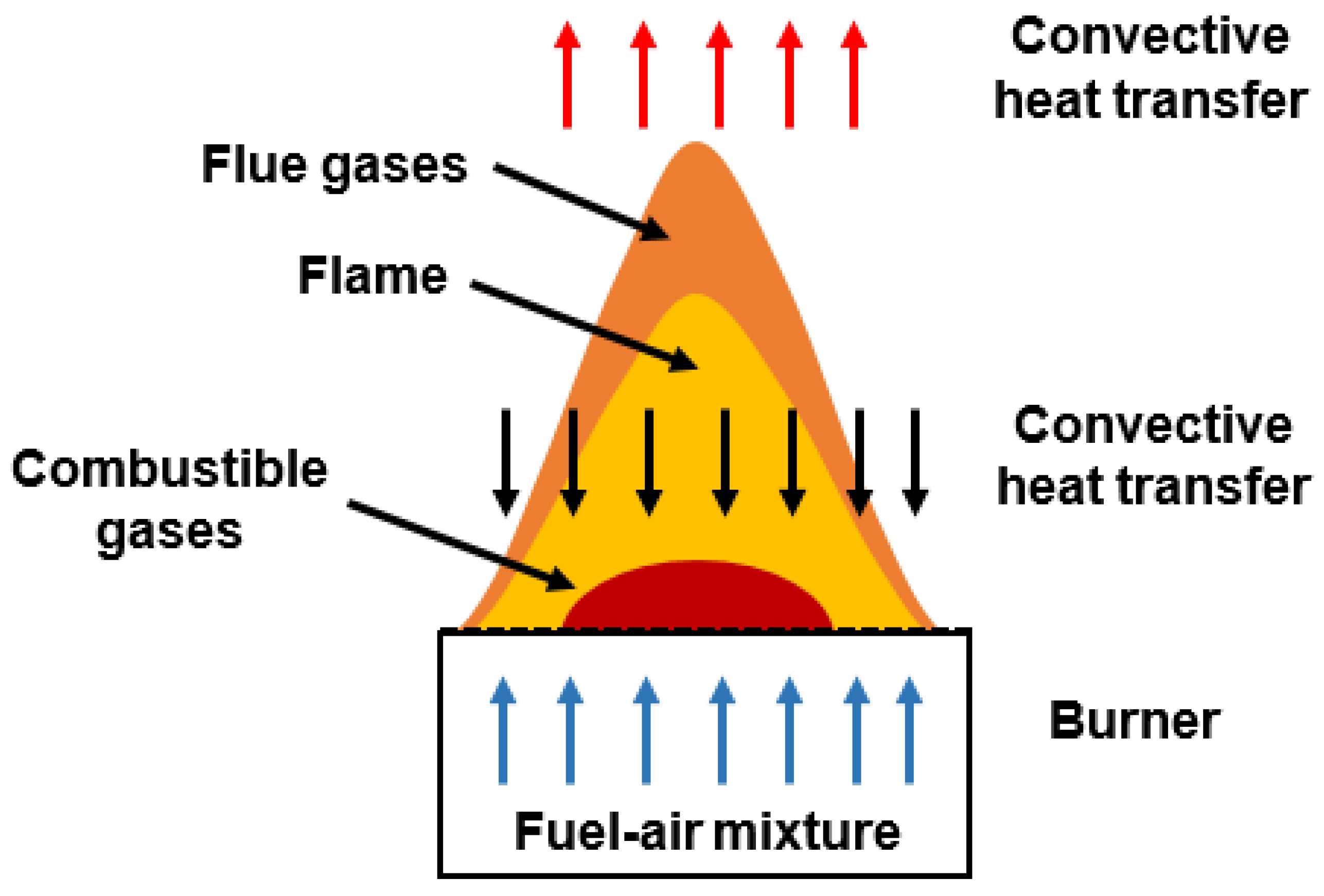
Figure 2. Schematic representation of combustion process in FFC-based cook-stove.
2.2. Cook-Stoves with Heat Recirculation Principle
As discussed above, only a part of the heat energy from the hot gas is transported to the load in FFC-based cook-stoves. This can be solved only by the efficient combustion of fuel–air mixture and an enhanced transfer of heat energy to the load, which could be effectively accomplished by providing means to recirculate the heat energy from the hot combustion products to the incoming fuel–air mixture without their direct mixing. The process of transferring enthalpy from the combustion products to the incoming fuel–air mixture is often termed ‘excess enthalpy burning’. Furthermore, the combustion process in burners operating on the heat recirculation principle can sustain in much leaner conditions than the flame in conventional burners. Higher burning velocities and flame temperatures are the characteristics of such flames, hence the name ‘superadiabatic’ combustion. Many researchers reviewed the heat-recirculation principle based burners and described their operation [24,25,26,27][19][20][21][22]. Cook-stoves with the heat recirculation principle can be classified into two groups: external heat recirculating burners and internal heat recirculating burners. The example of external heat recirculating burners is the Swiss roll burner [28][23], where the heat is transferred from hot product to cold reactant in a double spiral heat exchanger. Another example is the one which was developed by Jugjai and Sanitjai [29][24], where a Porous Medium (PM) was used to convert the enthalpy of the exhaust gases to thermal radiation which is then fed back to the burner inlet. On the other hand, internal heat recuperation is realized by facilitating the combustion in a PM. In the presence of a PM, the heat energy is transferred from the combustion zone (CZ) to the fresh reactants predominantly by conduction and radiation, leading to excess enthalpy or superadiabatic combustion [30][25]. Therefore, Porous Radiant Burners (PRBs) offer wider power modulation and flame stability range, lower emissions, and higher thermal efficiency than their FFC-based counterparts [31][26]. Figure 3 shows the heat transfer mechanism occurring in a double-layered PRB. The incoming fuel–air mixture is pre-heated by the heat recirculated from the CZ. The preheated mixture then undergoes combustion in the CZ. The preheating zone (PZ) with lower porosity also serves as a flame-arrestor [32][27]. The PM is also subjected to heat loss via radiation, convection, and conduction.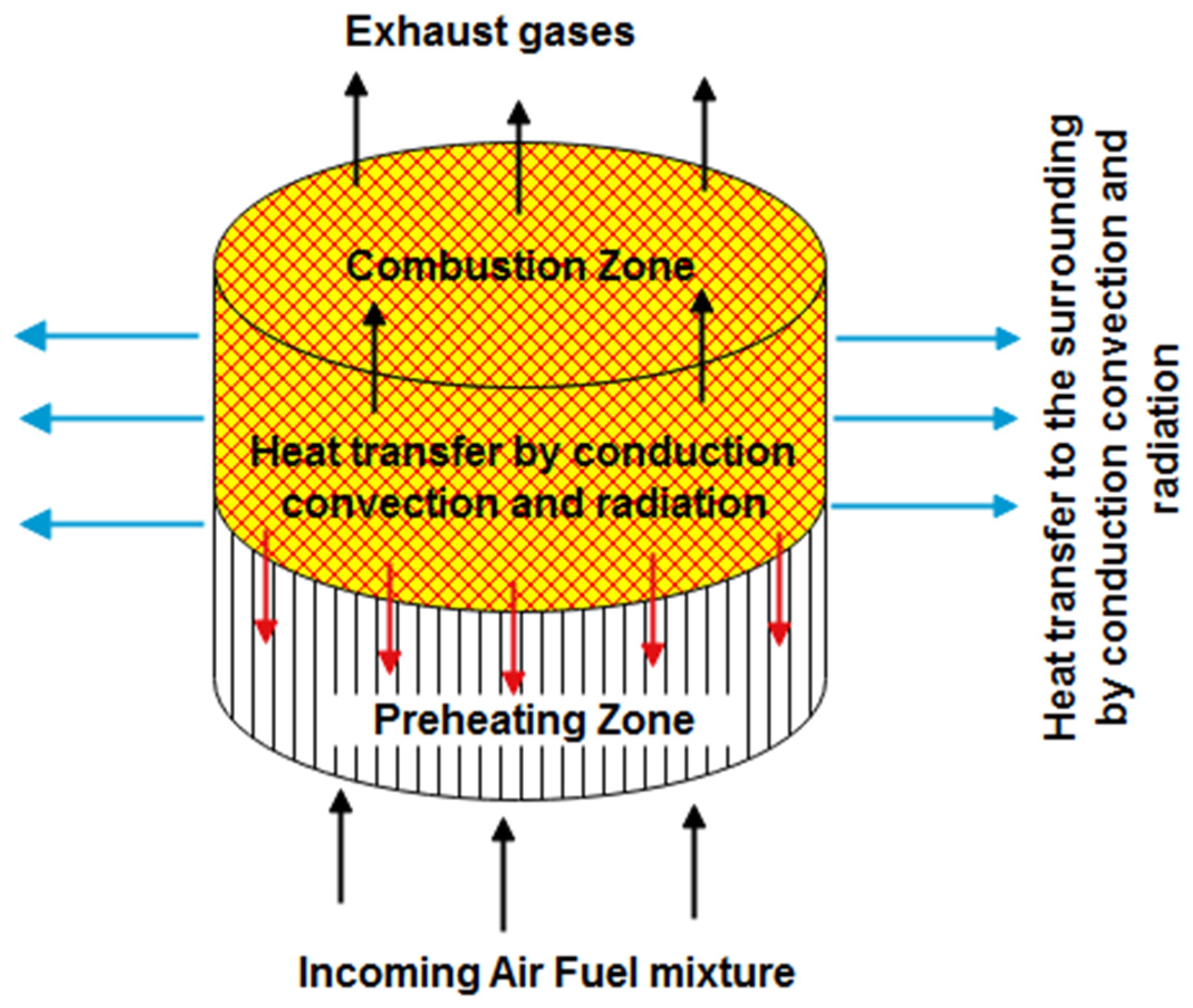
Figure 3. Heat transfer mechanism in a double layer PM.
3. Liquid Fuel-Based Cook-Stoves Operating Principles
In liquid fuel burners, the fuel is converted into droplets either by vaporization or atomization before being injected into a combustion device. Based on the mechanism of fuel vaporization and mixing with air/oxidizer, liquid fuel-based cook-stoves are classified as wick type, and pre-vaporizing and vaporizing type. The working of a wick type cook-stove is the same as that of a candle (Figure 4). In a wick type cook-stove, a thin film of fuel is formed on the surface of the wick that is soaked with the fuel and is heated by the flame initiated at the surface of the wick. As the fuel film evaporates, a diffusion flame sustains at the surface of the wick. Liquid fuel flows up from the tank to the flame portion through the wick by capillary action. Kerosene, plant oils, and alcohol are the most commonly used liquid fuels in wick type cook-stoves.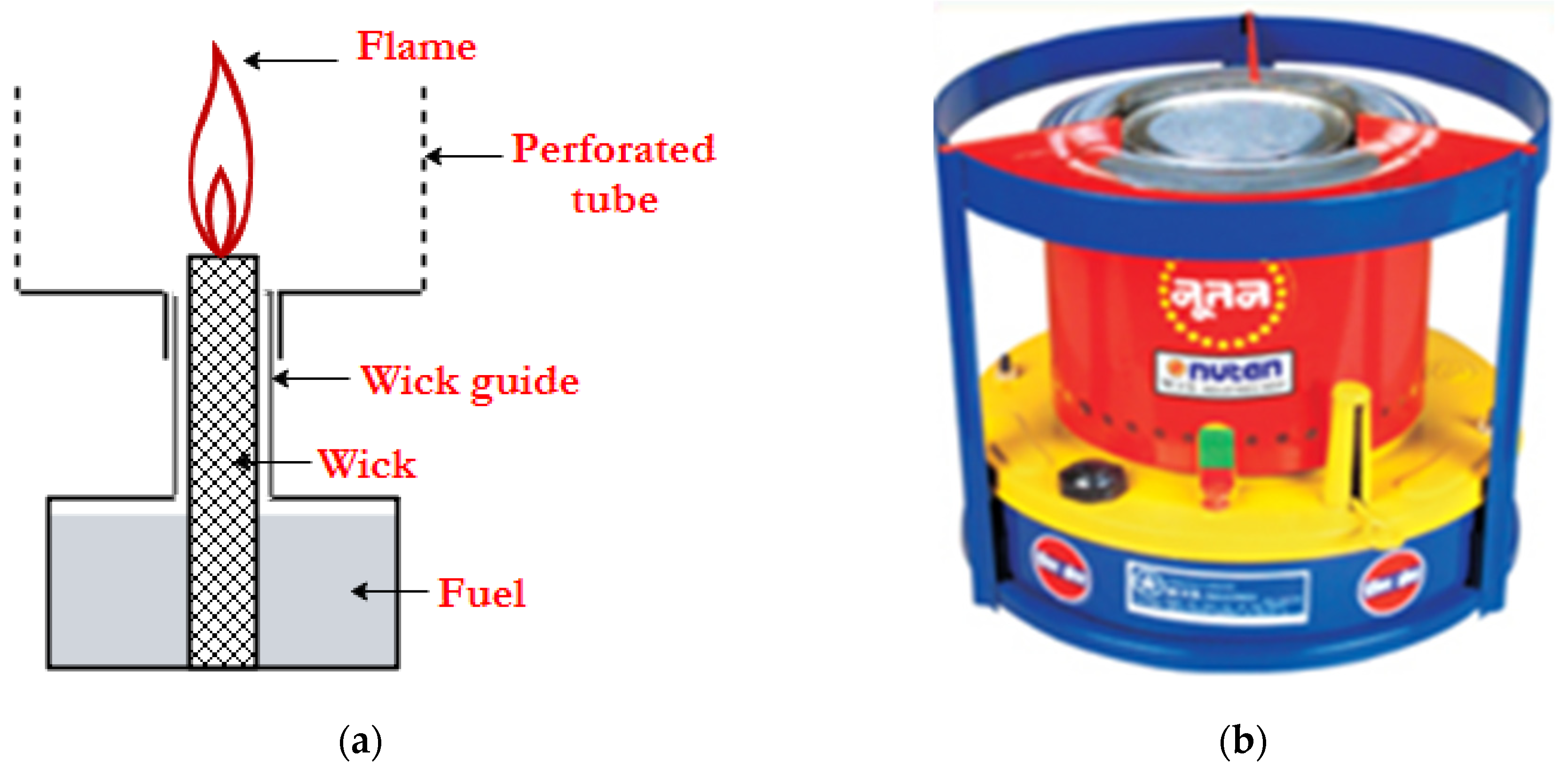
Figure 4. Schematic of wick type (a) burner and (b) cook-stove.
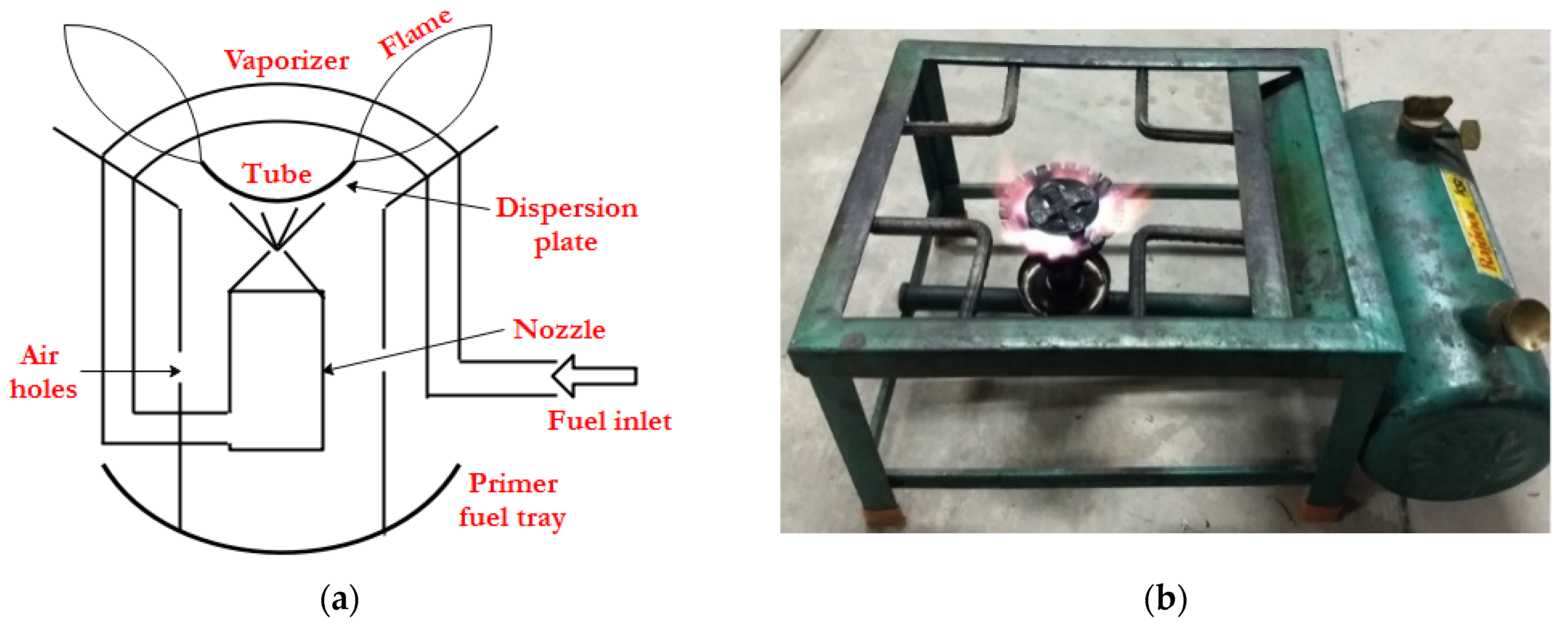
Figure 5. Schematic of pre-vaporizing type (a) burner and (b) cook-stove.
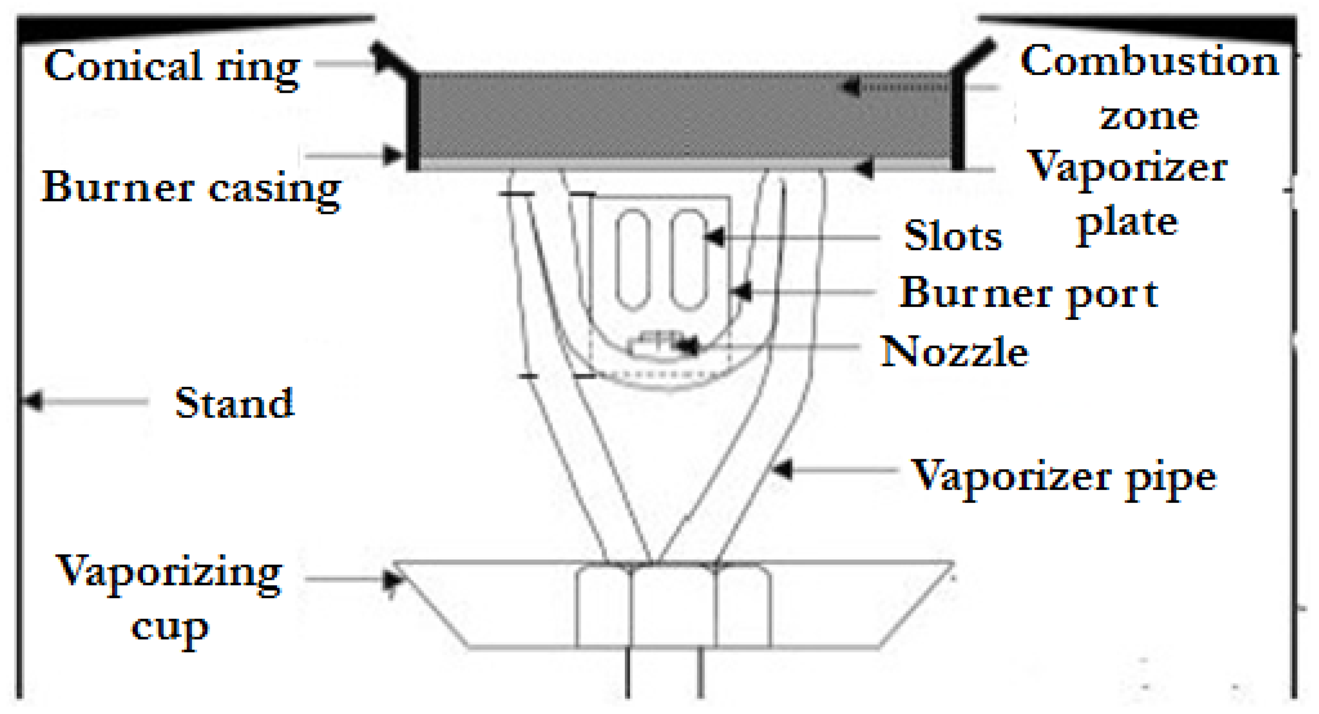
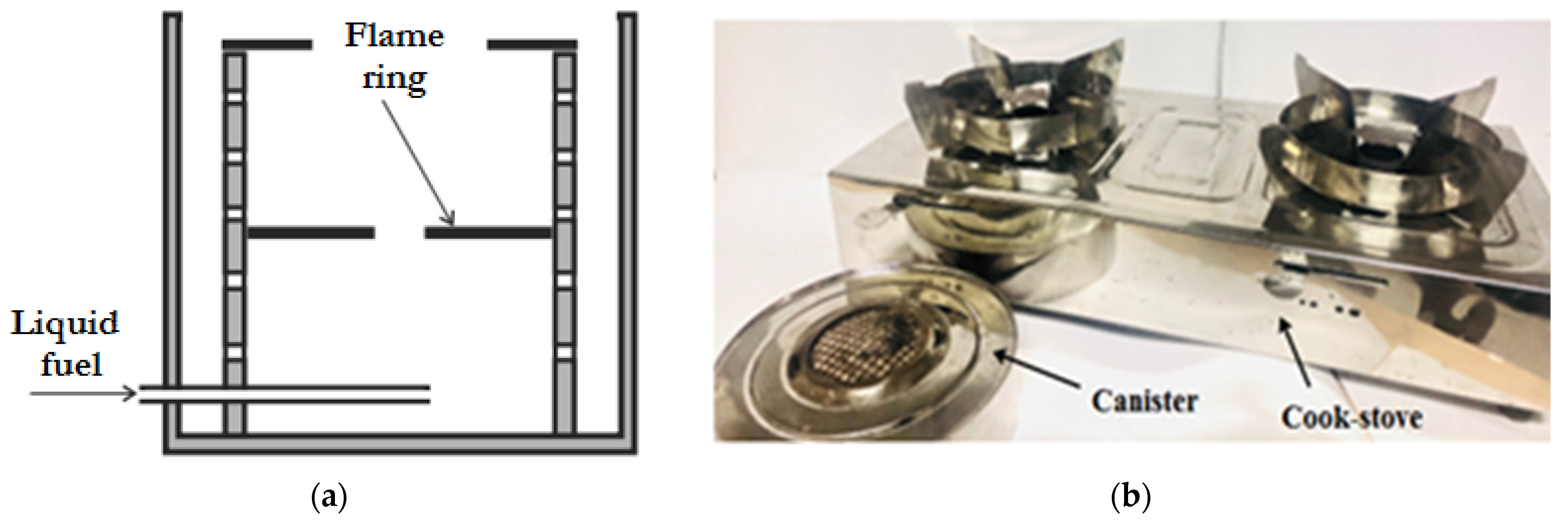
Figure 7. Schematic of vaporizing type (a) burner and (b) cook-stove.
4. Cook-Stove Designs
4.1. Gaseous Fuel Cook-Stove Designs
4.1.1. Liquefied Petroleum Gas (LPG)
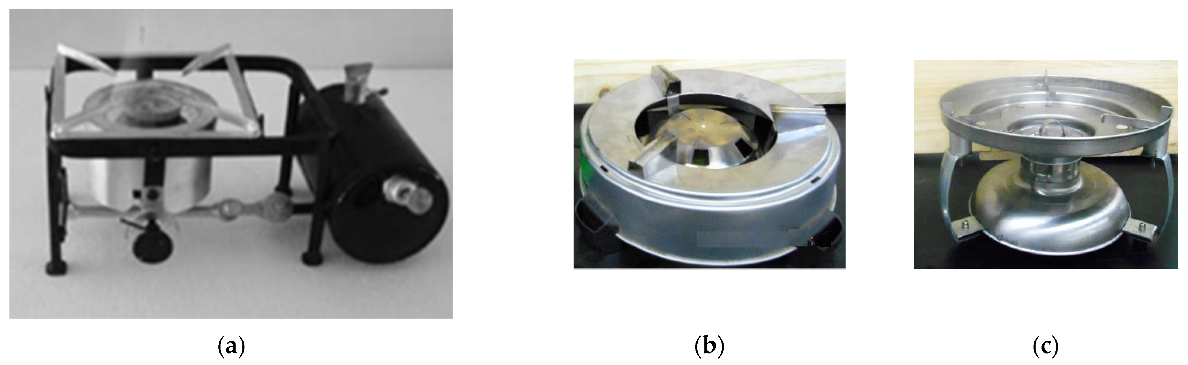
The traditional LPG cook-stoves are designed based on partially-aerated type burner design, as described by Berry et al. [34][29]. The traditional free-flame cook-stoves are generally based on the Bunsen burner design. In these designs, there are several holes located on the burner head where the flame jets are anchored. Most of the burner heads are made of metals such as cast iron or brass. The details of the various improved cook-stove designs (Figure 8). A venture center in Pune, India, developed a swirl flow-based LPG cook-stove for commercial cooking [35][30]. Zhen et al. [36][31] redesigned the traditional domestic cook-stove by modifying the burner cap to induce swirl flows (Figure 8b). The first design, Swirl Burner 1 consisted of 10 guided vanes that produced a continuous swirl. The radius and the inclination angles of the curvy channels were 3 mm and 10°, respectively. The second design, Swirl Burner 2 included both inward and swirling motion. The concave surfaces had an inclination angle of 30° towards the horizontal plane while the slots were at 10° off the normal direction of the surface. With the insertion of an annular metal insert and an extended spill-tray, Das et al. [37][32] improved the performance of traditional domestic cook-stoves. These improvements increased the heat transfer to the load by guiding the combustion products and air more towards the load.
As already mentioned, utilization of PM for improving the performance of traditional cook-stoves was demonstrated by Jugjai and Sanitjai [30][25] in their Porous Radiant Recirculated Burner (PRRB). PRRB is different from PRB, as it has an FF, and PM only promotes heat recirculation by recirculating the exhaust gas within the PM. Further, Jugjai and Rungsimuntuchart [38][33] developed a PRRB, i.e., PRRB (CB), using a ring burner. However, the swirling central flame ring burner (SB) and the PRRB were combined, i.e., the PRRB (SB), to further increase the burner’s thermal efficiency. Compared with their previous design [30][25], they scaled up the capacity of the burner from 5 kW to 30 kW. Mujeebu et al. [39][34] added another feather in the field of PRB cook-stoves by exploring the operation of double-layered PRBs on the surface and submerged combustion modes. These modes of PMC operation at the same power input were obtained by using different PMs. For a power input of 0.62 kW, a PRB with PZ and CZ of Alumina foams of different porosities was used to obtain surface stabilized flame, while PRBs formed by porcelain foam and alumina spheres were used to obtain a matrix stabilized flame. Another improved domestic PRB cook-stove based on the flat-flame operation was reported by Wu et al. [40][35]. The PRB was of diameter 50.8 mm and thickness 3 mm, and the PM was formed with bronze pellets of diameter 0.5 mm with a porosity of 0.237. Mishra [41][36] presented an improved cook-stove with a double-layer PRB for commercial cooking (5–10 kW). The PRB was of 120 mm diameter, and SiC and Alumina formed the CZ and PZ of PRB, respectively. Similarly, for domestic applications, Herrera et al. [42][37] developed 160 mm diameter PRB, where the preheater material was uniquely chosen from Alumina grinding wastes and the CZ comprised of SiSiC ceramic foam. Another milestone of PRB for domestic cooking was achieved by Mishra and Muthukumar, who developed a self-aspirated double layered PRB cook-stove operating at a power input range of 1–3 kW, marking the first of its kind [43][38]. The CZ and the PZ comprised of SiC reticulated foam and Alumina filter. These were enclosed in a housing made of refractory cement casing. This design was based on submerged PMC.

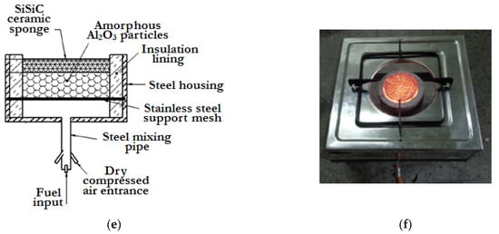
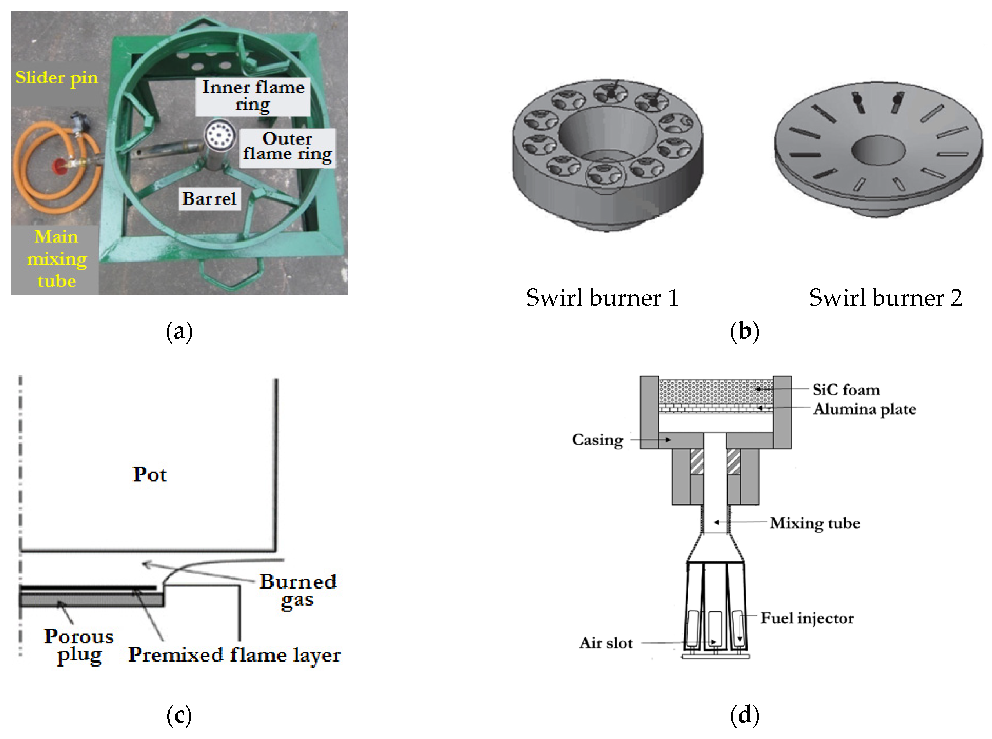
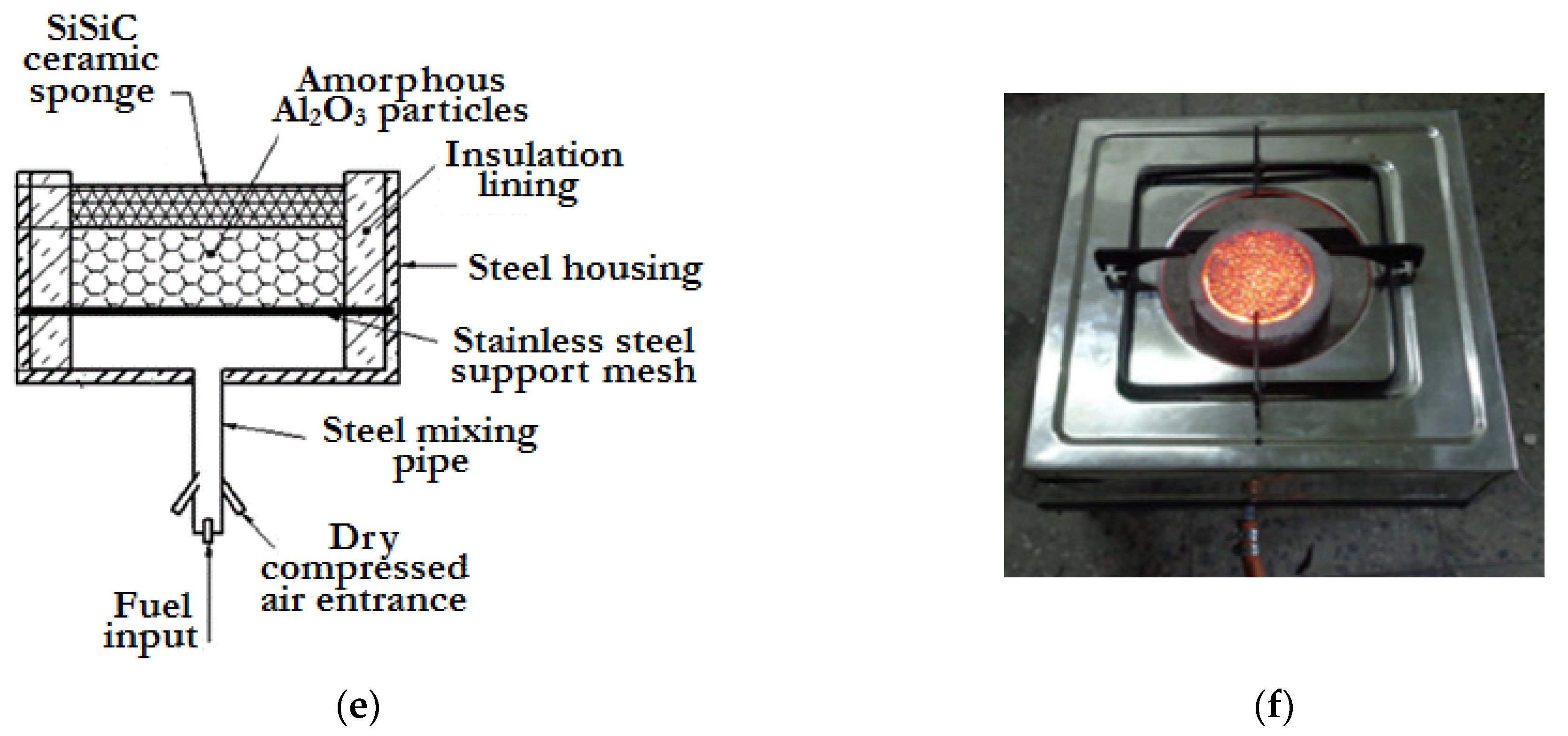
Figure 8. Improved LPG cook-stoves. (a) Improved cook-stove developed by Venture centre [35][30]; (b) Swirl burners developed by Zhen et al. [36][31]; (c) Porous metal burner developed by Wu et al. [40][35]; (d) Medium-scale PRB developed Mishra [41][36]; (e) Porous Radiant Burner developed by Herrera et al. [42][37]; (f) Domestic Porous Radiant Burner developed by Mishra and Muthukumar [43][38].
4.1.2. Biogas
Biogas-based cook-stove technology has been widely implemented in several countries such as India [44][39], China [45][40], Bangladesh [46][41], and Pakistan [47][42] with the subsidization of biogas plants. These cook-stoves are similar to the traditional LPG-based cook-stoves working on FFC [48][43] or PMC [49][44]. A biogas cook-stove usually has a single or double burner with different biogas consumption rates (Domestic burners: 1.2 to 5.5 kW; Commercial burners: 5.5 to 17 kW) [50][45]. The burner itself has several parts viz., Jet (Injector orifice), air intake holes, mixing tube (diffuser), flame port, baffle, burner manifold, frame, and the brackets welded on the top of it. There are two types of FFC-based biogas cook-stove designs: one is a modified design of the existing LPG cook-stoves and the other is the original design based on the properties of biogas [51][46]. In the early 1990s, Chandra et al. [52][47] presented analytical expressions for designing a burner in a biogas cook-stove. With the help of these expressions, for a given biogas pressure and pressure drop across the orifice, the design parameters of a biogas burner such as the orifice exit diameter, the spacing between the mixing tube and the orifice, the area of the burner head, and the number of burner port could easily be selected. In 1996, Fulford [50][45] presented a detailed design equation for a biogas cook-stove consistent with the scientific and technical criteria for low-pressure burners. They also presented a typical design calculation for a DCS cook-stove to supply about 1.5 kW for cooking. Using similar design principles, Kurchania et al. [53,54][48][49] developed a biogas cook-stove for cooking and baking corresponding to biogas consumption of 1 m3/h and 0.375 m3/h, respectively. Analogous designs of domestic cook-stoves can be found in the literature [48,55,56,57,58,59,60][43][50][51][52][53][54][55]. Recently, by using PMC, Kaushik et al. [49][44] developed a domestic double layer PRB cook-stove for biogas following the design of Mishra et al. [41][36] meant for LPG. The various biogas cook-stove designs are illustrated in Figure 9.

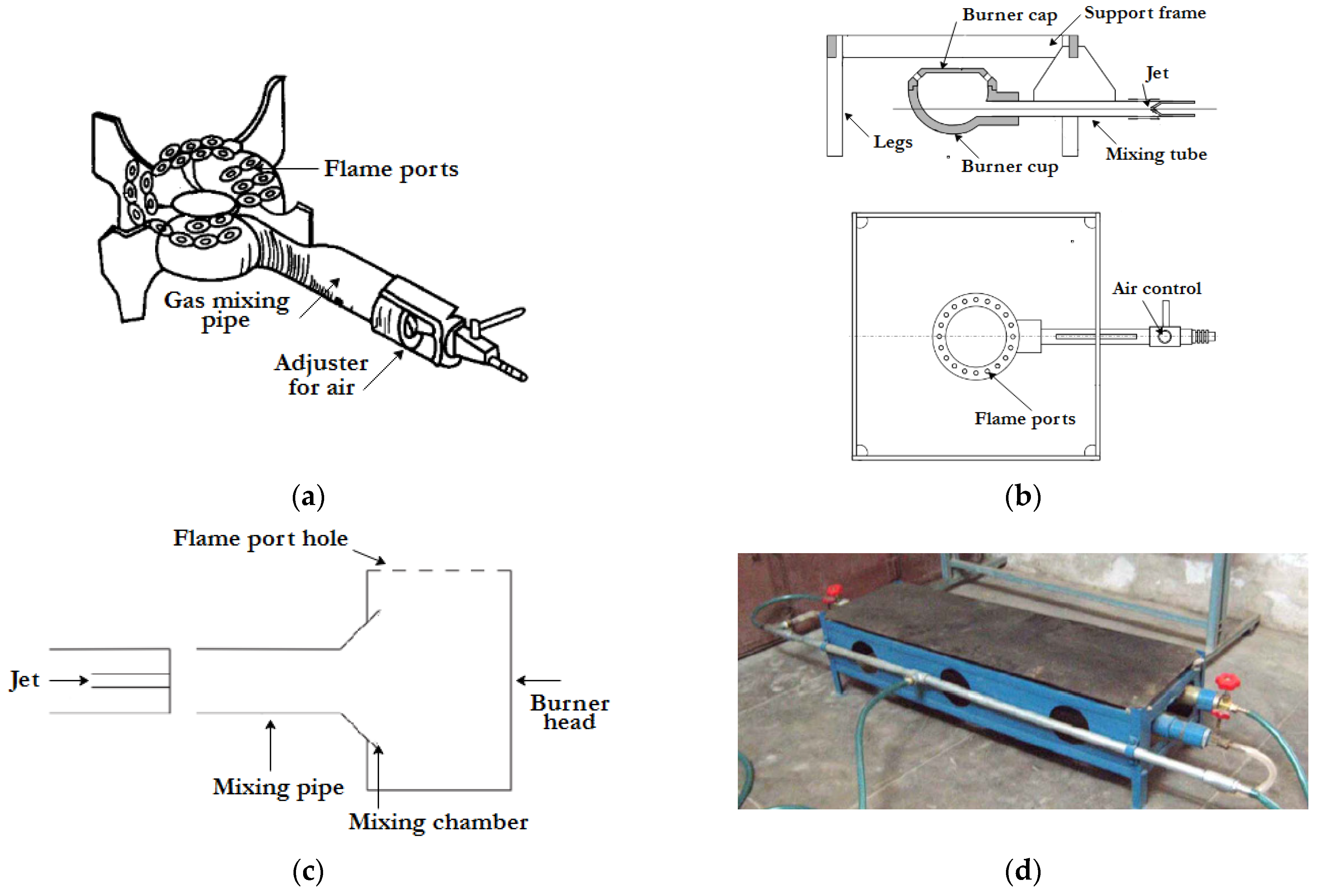
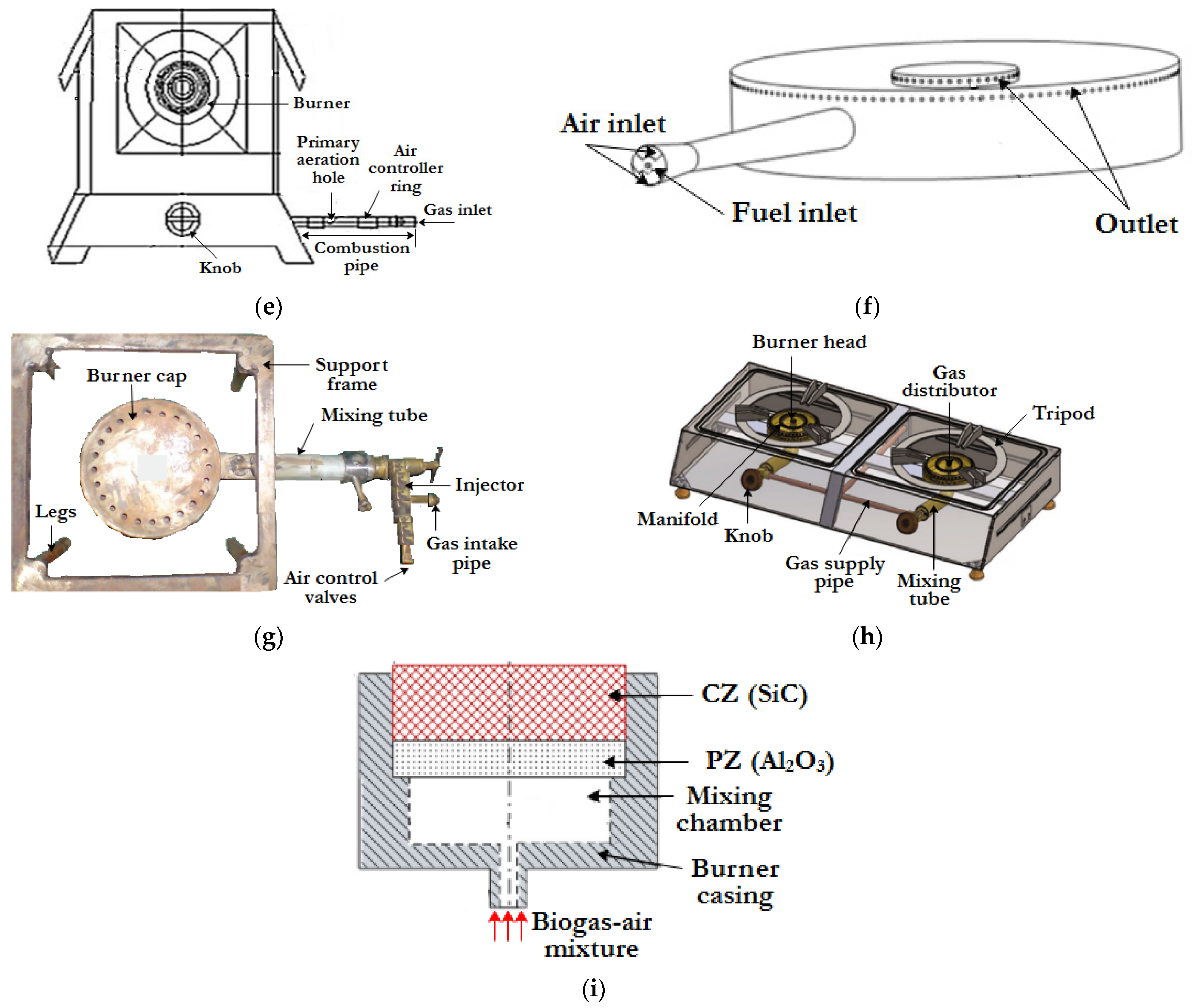
Figure 9. Biogas cook-stoves. (a) Biogas stove-KVIC model [55][50]; (b) DCS burner used in Nepal [50][45]; (c) Biogas stove designed by Itodo et al. [56][51]; (d) Biogas stove for baking developed by Kurchania et al. [53][48]; (e) Domestic biogas stove developed by Kurchania et al. [54][49]; (f) Biogas Injera baking burner [58][53]; (g) Biogas burner (Stove) developed by Awulu et al. [60][55]; (h) Biogas burner developed by Petro et al. [48][43]; (i) Biogas operated porous radiant burner developed by Kaushik et al. [49][44].
4.2. Liquid Fuel Cook-Stove Designs
Liquid fuels used for cooking applications can be categorized based on their sources as fossil fuels (e.g., kerosene), alcohols (e.g., ethanol, methanol), and plant oil (Figure 10). Liquid fuels can be easily stored, and most of them, being derived from plant-based sources, are renewable. Similar to gaseous fuel cook-stoves, the design features of liquid fuel cook-stoves are influenced by the burner parts that enable the smooth flow and combustion of the fuel. The most important design improvements involve the selection of the wick materials in the case of wick type cook-stoves and the design of the vaporizer in the case of pressurized cook-stoves.

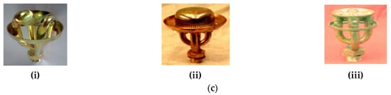
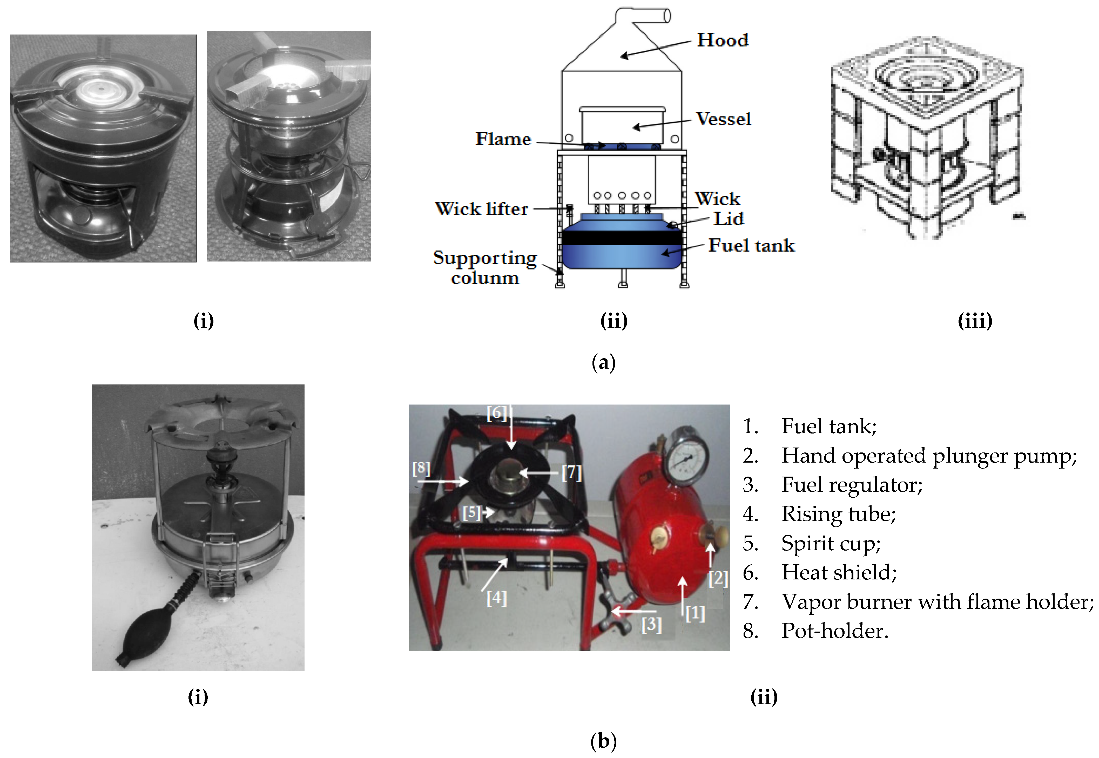
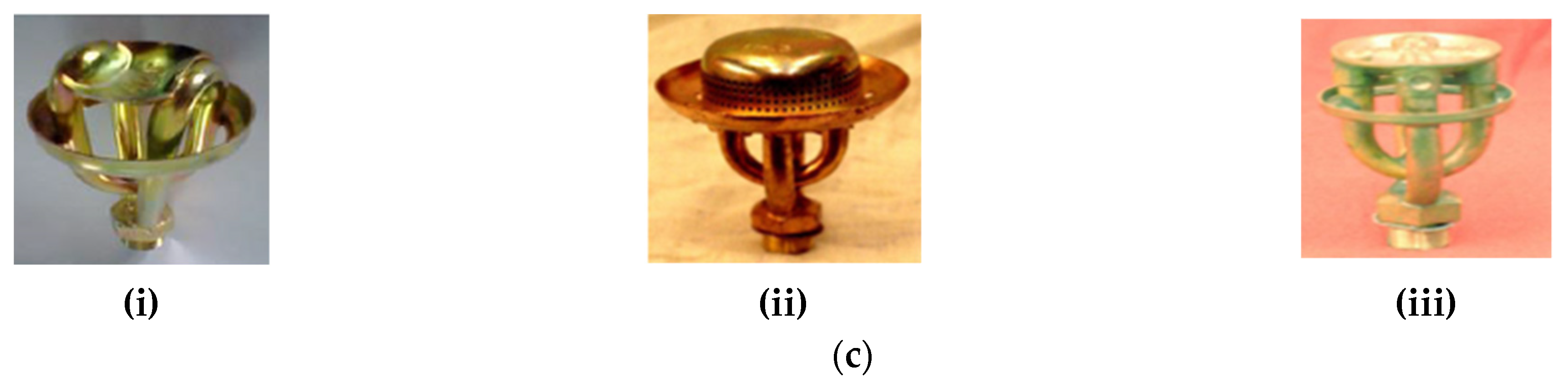
Figure 10. (a) Different designs of kerosene wick stoves—(i) kerosene wick (woven fiberglass) stove [61][56], (ii) kerosene wick (10 no. of wick) stove [62][57] and (iii) kerosene wick (8 no. of wick) stove [63][58]; (b) Different types of kerosene pressurized stove—(i) kerosene pressure stove (Roarer type burner) [61][56] and (ii) kerosene pressure stove [33][28]; and (c) Kerosene pressure cook-stove burners [33][28]—(i) Venus burner, (ii) Silencer type burner and (iii) Roarer type burner.
4.2.1. Kerosene
There are currently two kinds of kerosene-fueled cook-stoves: wick stove [61][56], which relies on the capillary action for the transfer of fuel, and a pressure cook-stove [61,64][56][59] with the vapor-jet arrangement, which aerosolizes the fuel using manual pumping. Different designs of both types of cook-stoves and the burner head assembly of pressure cook-stoves are shown in Figure 11. In terms of safety, the pressure stove is ranked higher than the wick stove.
4.2.2. Alcohol
The production of alcohol shows an increasing trend around the world, and attempts have been made from the mid-2000s to commercialize alcohol-based cook-stoves (Figure 11). The use of ethanol and methanol as cooking fuels was first seen in Ethiopia through the ‘Project Gaia’ initiative [67,68][62][63]. The cook-stove under this project was a canister-based methanol-/ethanol-operated Origo stove [69,70][64][65] manufactured by a Swedish company. These stoves carry a 1.2 L canister and weigh around 1.8 kg. One fill of the canister in this cook-stove can operate for about 6–8 h. In another study, Nimbkar Agricultural Research Institute (NARI) developed an ethanol-pressurized cook-stove working on a 50% ethanol-water mixture [65][60]. The stove produces outputs comparable to that of the traditional LPG and kerosene stoves and provides for simple flame regulation. Another ethanol stove operating without a pressure system is the “VOAHAJA” stove. The burner is designed to convert the water in the ethanol into steam, and the resulting flame is blue and odorless [71][66]. In a different study, two prototype stoves operating on methanol and ethanol gel were reported by Masekameni et al. [66][61], but their details are not available.
References
- IEA; International Renewable Energy Agency; United Nations Statistics Division; The World Bank; World Health Organization. Tracking SDG7: The Energy Progress Report 2020; Report; IEA: Paris, France, 2020.
- Clean Cooking Alliance: Delivering on the Sustainable Development Goals through Clean Cooking. Available online: https://www.cleancookingalliance.org/feature/delivering-on-the-sustainable-development-goals-through-clean-cooking.html (accessed on 28 December 2022).
- IEA; International Renewable Energy Agency; United Nations Statistics Division; The World Bank; World Health Organization. Tracking SDG 7: The Energy Progress Report 2019; Report; IEA: Paris, France, 2019.
- Turner, B. Energy Challenges for Clean Cooking in Asia, the Background, and Possible Policy Solutions; Working Paper 1007; Asian Development Bank Institute: Mandaluyong, Philippines, 2014.
- Quinn, A.K.; Bruce, N.; Puzzolo, E.; Dickinson, K.; Sturke, R.; Jack, D.W.; Mehta, S.; Shankar, A.; Sherr, K.; Rosenthal, J.P. An Analysis of Efforts to Scale up Clean Household Energy for Cooking around the World. Energy Sustain. Dev. 2018, 46, 1–10.
- World Health Organization. Burning Opportunity: Clean Household Energy for Health, Sustainable Development, and Wellbeing of Women and Children; WHO: Geneva, Switzerland, 2016; ISBN 9789241565233. NLM Classification: WA 754.
- World Health Organization. Household Air Pollution and Health. Available online: https://www.who.int/news-room/fact-sheets/detail/household-air-pollution-and-health (accessed on 28 December 2022).
- Alem, Y.; Beyene, A.D.; Köhlin, G.; Mekonnen, A. Modeling Household Cooking Fuel Choice: A Panel Multinomial Logit Approach. Energy Econ. 2016, 59, 129–137.
- Paudel, U.; Khatri, U.; Pant, K.P. Understanding the Determinants of Household Cooking Fuel Choice in Afghanistan: A Multinomial Logit Estimation. Energy 2018, 156, 55–62.
- Rahut, D.B.; Ali, A.; Mottaleb, K.A.; Aryal, J.P. Wealth, Education and Cooking-Fuel Choices among Rural Households in Pakistan. Energy Strateg. Rev. 2019, 24, 236–243.
- Liao, H.; Chen, T.; Tang, X.; Wu, J. Fuel Choices for Cooking in China: Analysis Based on Multinomial Logit Model. J. Clean. Prod. 2019, 225, 104–111.
- Menghwani, V.; Zerriffi, H.; Dwivedi, P.; Marshall, J.D.; Grieshop, A.; Bailis, R. Determinants of Cookstoves and Fuel Choice among Rural Households in India. Ecohealth 2019, 16, 21–60.
- Yasmin, N.; Grundmann, P. Home-Cooked Energy Transitions: Women Empowerment and Biogas-Based Cooking Technology in Pakistan. Energy Policy 2020, 137, 111074.
- Anenberg, S.C.; Balakrishnan, K.; Jetter, J.; Masera, O.; Mehta, S.; Moss, J.; Ramanathan, V. Cleaner Cooking Solutions to Achieve Health, Climate, and Economic Cobenefits. Environ. Sci. Technol. 2013, 47, 3944–3952.
- World Health Organization. Air Pollution, Technology and Design-Based Interventions. Available online: https://www.who.int/airpollution/household/interventions/technology/en/ (accessed on 28 December 2022).
- Jones, H.R.N. The Application of Combustion Principles to Domestic Gas Burner Design; Taylor & Francis: Milton Park, UK, 2005.
- Pantangi, V.K. Development and Performance Analysis of Porous Radiant Burners for Cooking Applications. Ph.D. Thesis, Indian Institute of Technology, Guwahati, India, 2010.
- Avdic, F. Application of the Porous Medium Gas Combustion Technique to Household Heating Systems with Additional Energy Sources. Doctoral Thesis, Universität Erlangen-Nürnberg, Erlangen, Germany, 2004.
- Mujeebu, M.A.; Abdullah, M.Z.; Mohamad, A.A.; Abu Bakar, M.Z. Trends in Modeling of Porous Media Combustion. Prog. Energy Combust. Sci. 2010, 36, 627–650.
- Howell, J.R.; Hall, M.J.; Ellzey, J.L. Combustion of Hydrocarbon Fuels within Porous Inert Media. Prog. Energy Combust. Sci. 1996, 22, 121–145.
- Wood, S.; Harris, A.T. Porous Burners for Lean-Burn Applications. Prog. Energy Combust. Sci. 2008, 34, 667–684.
- Mujeebu, M.A.; Abdullah, M.Z.; Abu Bakar, M.Z.; Mohamad, A.A.; Abdullah, M.K. Applications of Porous Media Combustion Technology—A Review. Appl. Energy 2009, 86, 1365–1375.
- Chen, C.-H.; Gowdagiri, S.; Kumar, S.; Ronney, P.D. Numerical and Experimental Study in Swiss Roll Heat-Recirculating Burner. In Proceedings of the 9th International Conference on Micro and Nanotechnology for Power Generation and Energy Conversion Applications, Washington, DC, USA, 1–4 December 2009; pp. 605–608.
- Jugjai, S.; Sanitjai, S. Parametric Studies of Thermal Efficiency in a Proposed Porous Radiant Recirculated Burner (PRRB): A Design Concept for the Future Burner. RERIC Int. Energy J. 1996, 18, 97–111.
- Vafai, K. Handbook of Porous Media, 2nd ed.; CRC Press; Taylor & Francis Group: Boca Raton, FL, USA, 2015.
- Mujeebu, M.A.; Abdullah, M.Z.; Abu Bakar, M.Z.; Mohamad, A.A.; Muhad, R.M.N.; Abdullah, M.K. Combustion in Porous Media and Its Applications—A Comprehensive Survey. J. Environ. Manag. 2009, 90, 2287–2312.
- Khanna, V.; Goel, R.; Ellzey, J.L. Measurements of Emissions and Radiation for Methane Combustion within a Porous Medium Burner. Combust. Sci. Technol. 1994, 99, 133–142.
- Sinha, G.S. Development and Performance Analysis of Self-Aspirated Porous Radiant Burners for Kerosene Pressure Stove. Ph.D. Thesis, Indian Institute of Technology, Guwahati, India, 2017.
- Berry, W.M.; Brumbaugh, I.V.; Moulton, G.F.; Shawn, G.B. Design of Atmospheric Gas Burners, No. 193; Technologic Papers of the Bureau of Standards; Washington Government Printing Office: Washington, DC, USA, 1921.
- Technology Refinement and Marketing Programme (TREMAP). An Indigennous Design of LPG Burner for Commmercial Cooking; TREMAP, Venture Center (Entrepreneurship Development Center): Pune, India, 2007.
- Zhen, H.S.; Leung, C.W.; Wong, T.T. Improvement of Domestic Cooking Flames by Utilizing Swirling Flows. Fuel 2014, 119, 153–156.
- Das, M.; Ganguly, R.; Datta, A.; Verma, M.M.; Bera, A.K. Performance Improvement of a Domestic Liquefied Petroleum Gas Cook Stove Using an Extended Spill-Tray and an Annular Metal Insert. J. Therm. Sci. Eng. Appl. 2021, 13, 021016.
- Jugjai, S.; Rungsimuntuchart, N. High Efficiency Heat-Recirculating Domestic Gas Burners. Exp. Therm. Fluid Sci. 2002, 26, 581–592.
- Mujeebu, M.A.; Abdullah, M.Z.; Mohamad, A.A. Development of Energy Efficient Porous Medium Burners on Surface and Submerged Combustion Modes. Energy 2011, 36, 5132–5139.
- Wu, C.Y.; Chen, K.H.; Yang, S.Y. Experimental Study of Porous Metal Burners for Domestic Stove Applications. Energy Convers. Manag. 2014, 77, 380–388.
- Mishra, N.K. Development of Self-Aspirated Two-Layer Porous Radiant Burners for LPG Cooking Applications. Ph.D. Thesis, Indian Institute of Technology, Guwahati, India, 2015.
- Herrera, B.; Cacua, K.; Olmos-Villalba, L. Combustion Stability and Thermal Efficiency in a Porous Media Burner for LPG Cooking in the Food Industry Using Al2O3 Particles Coming from Grinding Wastes. Appl. Therm. Eng. 2015, 91, 1127–1133.
- Mishra, N.K.; Muthukumar, P. Development and Testing of Energy Efficient and Environment Friendly Porous Radiant Burner Operating on Liquefied Petroleum Gas. Appl. Therm. Eng. 2018, 129, 482–489.
- Ministry of New & Renewable Energy—Government of India. Available online: https://mnre.gov.in/ (accessed on 28 December 2022).
- Giwa, A.S.; Ali, N.; Ahmad, I.; Asif, M.; Guo, R.B.; Li, F.L.; Lu, M. Prospects of China’s Biogas: Fundamentals, Challenges and Considerations. Energy Rep. 2020, 6, 2973–2987.
- Bangladesh National Biogas Program Monitoring Services. Available online: https://www.upm-cdm.eu/project/bangladesh-national-biogas-program-monitoring-services-12/ (accessed on 28 December 2022).
- Yasmin, N.; Grundmann, P. Adoption and Diffusion of Renewable Energy—The Case of Biogas as Alternative Fuel for Cooking in Pakistan. Renew. Sustain. Energy Rev. 2019, 101, 255–264.
- Petro, L.M.; Machunda, R.; Tumbo, S.; Kivevele, T. Theoretical and Experimental Performance Analysis of a Novel Domestic Biogas Burner. J. Energy 2020, 2020, 8813254.
- Kaushik, L.K.; Mahalingam, A.K.; Palanisamy, M. Performance Analysis of a Biogas Operated Porous Radiant Burner for Domestic Cooking Application. Environ. Sci. Pollut. Res. 2021, 28, 12168–12177.
- Fulford, D. A Short Course on Biogas Stove Design; Kingdom Bioenergy, Ltd.: Wokingham, UK, 1996.
- Sasse, L.; Kellner, C.; Kimaro, A. Improved Biogas Unit for Developing Countries; Deutsche Gesellschaft für Technische Zusammenarbeit (GTZ) GmbH: Eschborn, Germany, 1991.
- Chandra, A.; Tiwari, G.N.; Yadav, Y.P. Hydrodynamical Modelling of a Biogas Burner. Energy Convers. Manag. 1991, 32, 395–401.
- Kurchania, A.K.; Panwar, N.L.; Pagar, S.D. Design and Performance Evaluation of Biogas Stove for Community Cooking Application. Int. J. Sustain. Energy 2010, 29, 116–123.
- Kurchania, A.K.; Panwar, N.L.; Pagar, S.D. Development of Domestic Biogas Stove. Biomass Convers. Biorefinery 2011, 1, 99–103.
- Kandpal, J.B.; Maheshwari, R.C.; Kandpal, T.C. Indoor Air Pollution from Combustion of Wood and Dung Cake and Their Processed Fuels in Domestic Cookstoves. Energy Convers. Manag. 1995, 36, 1073–1079.
- Itodo, I.N.; Agyo, G.E.; Yusuf, P. Performance Evaluation of a Biogas Stove for Cooking in Nigeria. J. Energy S. Afr. 2007, 18, 14–18.
- Syamsuri, S.; Yustia, W.M. Performance Analysis of Biogas Stoves with Variations of Flame Burner for the Capacity of Biogas 1 M3/Day. ARPN J. Eng. Appl. Sci. 2015, 10, 10349–10353.
- Mulugeta, B.; Nega, D.T.; Demissie, S.W. Design, Optimization and CFD Simulation of Improved Biogas Burner for ‘Injera’ Baking in Ethiopia. Int. J. Eng. Res. Technol. 2017, 6, 58–63.
- Decker, T.; Baumgardner, M.; Prapas, J.; Bradley, T. A Mixed Computational and Experimental Approach to Improved Biogas Burner Flame Port Design. Energy Sustain. Dev. 2018, 44, 37–46.
- Awulu, J.O.; Iyidiobu, B.N.; Ugbede, J. Cooking Performance of a Developed Biogas Burner (Stove). Int. J. Eng. Appl. Sci. Technol. 2020, 4, 11–16.
- Makonese, T.; Pemberton-Pigott, C.; Robinson, J.; Kimemia, D.; Annegarn, H. Performance Evaluation and Emission Characterisation of Three Kerosene Stoves Using a Heterogeneous Stove Testing Protocol (HTP). Energy Sustain. Dev. 2012, 16, 344–351.
- Dinesha, P.; Kumar, S.; Rosen, M.A. Performance and Emission Analysis of a Domestic Wick Stove Using Biofuel Feedstock Derived from Waste Cooking Oil and Sesame Oil. Renew. Energy 2019, 136, 342–351.
- MacCarty, N.; Still, D.; Ogle, D. Fuel Use and Emissions Performance of Fifty Cooking Stoves in the Laboratory and Related Benchmarks of Performance. Energy Sustain. Dev. 2010, 14, 161–171.
- Mishra, S.C.; Muthukumar, P.; Sinha, G.S.; Sharma, M.; Mishra, N.K. Self Aspirated Pressurized Kerosene Cooking Stove with a Porous Radiant Burner. Application No: 201631037245, 31 October 2016.
- Rajvanshi, A.K.; Patil, S.M.; Mendonca, B. Low-Concentration Ethanol Stove for Rural Areas in India. Energy Sustain. Dev. 2007, 11, 94–99.
- Masekameni, M.D.; Makonese, T.; Annegarn, H.J. A Comparison of Emissions and Thermal Efficiency of Three Improved Liquid Fuel Stoves. In Proceedings of the 2015 International Conference on the Domestic Use of Energy (DUE), Cape Town, South Africa, 31 March–1 April 2015; IEEE: New York, NY, USA, 2015; pp. 71–76.
- Jetter, J.; Ebersviller, S.; Williams, C.; Faircloth, J. Test Report-CleanCook Model A1 Stove with Alcohol Fuel-Air Pollutant Emissions and Fuel Efficiency; US Environmental Protection Agency: Cincinnati, OH, USA, 2015.
- Murren, J.; Debebe, M. Project Gaia’s Ethanol-Fueled CleanCook Stove Initiative and Its Impact on Traditional Cooking Fuels Used in Addis Ababa, Ethiopia; Shell Foundation Project Number: 21311; Addis Ababa Sub-cities Fuel Use Report; GAIA Association: Washington, DC, USA, 2006.
- Dometic ORIGO 3000 Double Burner—Non-Pressurized Alcohol Stove. Available online: https://www.marine.com/products/11-67992/dometic-origo-3000-single-burner-non-pressurized-alcohol-stove (accessed on 28 December 2022).
- Swanepoel, S.; Niekerk, V. Nova Report on Reseach into Domestic Stove Requirements and the Desirability of Methanol as Fuel on Behalf of Origo-Electrolux; Report. 2001. Available online: https://projectgaia.com/files/2001SouthAfricaORIGO3000.pdf (accessed on 28 December 2022).
- Hajamalala, A.M. Thermal Performance of a Low-Concentration Ethanol Stove without Pressure System. Curr. Sci. 2014, 107, 289–296.
More