Your browser does not fully support modern features. Please upgrade for a smoother experience.
Please note this is a comparison between Version 1 by Abilio P. Silva and Version 2 by Rita Xu.
The quest for increased performance in the aeronautical and aerospace industries has provided the driving force and motivation for the research, investigation, and development of advanced ceramics. Special emphasis is therefore attributed to the ability of fine ceramics to fulfill an attractive, extreme, and distinguishing combination of application requirements. This research provides an extensive discussion and review of the thermal protection systems (TPS), thermal protection barriers (TBC), and dielectric barrier discharge (DBD) plasma actuators, and discusses the concept of multifunctional advanced ceramics for future engineering needs and perspectives.
- thermal protection systems
- thermal barrier coatings
- dielectric barrier discharge
- multifunctional ceramics
1. Introduction
Advanced ceramics are inorganic, nonmetallic solids, basically crystalline materials of rigorously controlled composition and raw materials that are prepared from powdered materials and fabricated into products through the application of heat, which display properties such as hardness, strength, low electrical conductivity, and brittleness [1][2][3][1,2,3]. In this way, the term advanced ceramics refers to high-performance, high-tech, engineered, fine, or technical ceramics, i.e., materials with highly specialized and unique properties capable of outstanding performance under the most extreme conditions and, consequently, able to solve today’s challenges in research, manufacturing, and use.
Concerning high-performance ceramics, a distinction is made between structural and functional ceramics. Briefly, advanced structural ceramics are conventionally best suited in mechanical, structural, tribological, thermal, or chemical load applications, owing to their chemically inert nature, high compression, flexural strength, and toughness, in addition to their high corrosion, wear, and thermal shock resistance. In contrast, advanced functional ceramic applications are based on their functional capabilities ruled by microstructural effects that involve semiconducting, piezoelectric, ferroelectric, pyroelectric, and superconducting properties. Nevertheless, from a chemical composition perspective, two classes of fine ceramics may be identified: oxide and non-oxide ceramics. Oxide ceramics are recognized for properties such as oxide resistance, chemical inertness, thermal non-conductivity, and electrical insulation with a slightly complex manufacturing process. Conversely, non-oxide ceramics are characterized by low oxide resistance, being extremely hard, chemically inert, highly thermally and electrically conductive (due to their covalent bonding), highly energy-dependent to manufacture, and quite expensive [1][2][3][1,2,3].
Considering the versatility of advanced ceramics, this sector comprises different fields inscribed with new challenges in exploring the concept of multifunctional ceramics, which are materials still with unexplored potential, namely [3]:
- -
-
Structural ceramics where enhancement of the mechanical properties (based on affordable raw materials, optimized technologies, and simulations of the complete process chain) as well as exploration of the reliability of the materials (by auxiliary sensor integration for structural health control or even self-healing ceramics) are mandatory.
- -
-
Miniaturization and integration density of devices and systems. To this aim, better understanding and control of corresponding changes in specific properties of materials, new testing, and measurement methods are crucial.
- -
-
Modeling is a sensitive issue of uplift since complete production chains and faithful multi-scale modeling (digital twins) must be matured for new materials and devices with higher emphasis in cases of coupled (multifunctional) properties.
- -
-
Functional ceramics in which defective structure (atomic and electronic) dissemination should be achieved to take advantage of full temperature dependence.
- -
-
Functional ceramics and property enhancement allow investigation of multifunctional ceramics exhibiting additive effects, based on the coupling of their properties. These effects are little explored, yet they promise to provide and stimulate scientific and technological advancements henceforward.
To leverage the entire innovative potential of advanced ceramics, new lines of research are needed to guarantee the sustainable development and growth of the advanced ceramic materials market using accessible raw materials and preferably with optimized energy costs. Thus, it is essential to know the properties required for a component subject to multiple functions.
The quest for increased performance in the aeronautical and aerospace industries has provided the driving force for the development of high-temperature ceramics with attractive combinations of thermomechanical properties, oxidation resistance, as well as low-to-moderate density [4]. One of the most common and well-known uses for high-performance ceramics in aviation, rocketry, and space technologies is as part of thermal protection systems. This application of ceramics protects the intended components against hazardous aerothermal environments. Examples of thermal protection systems can be encountered in coatings of various heat-resisting materials for aircraft engine nacelle, thrust reverser fire protection, helicopter cowlings, gas turbine engines, satellites, rockets, and re-entry vehicles [5]. In addition to thermal protection itself, the coating enables higher operating temperatures, consequently increasing, for example, an engine’s combustion efficiency, which in turn reduces consumption and harmful residual emissions. Additionally, another application is shielding against foreign objects. Examples of shielding purposes based on advanced ceramic materials include the conservation and safety of propulsion components from existing particles in the surroundings or residuals resulting from poor combustion processes, space debris, or micrometeoroid particles in the case of a spacecraft or rocket [6].
Lastly, an important field of application of high-tech ceramics is electroceramics, a specific category in which materials are combined with specific characteristics, such as piezoelectric and dielectric properties and corrosion and thermal resistance, for use in aircraft instrumentation and control systems, such as missile guidance systems, satellite positioning equipment, ignition systems, instrument display, and engine monitoring equipment [7].
2. Advanced Ceramics in Aerospace and Aeronautical Engineering
2.1. Thermal Protection System (TPS)
Thermal protection systems (TPSs) play a crucial role in the aerospace and aeronautical industries as they are single point of failure systems that work above all as thermal shields, i.e., a subsystem that protects structures, aerodynamic surfaces, payload of probes, missiles, warheads, and space vehicles from severe aerothermodynamic heating. Accordingly, an effective TPS system must uphold a reliable shield against aerothermal loads, without adding significant weight penalties or compromising the structure of the vehicle. Nonetheless, TPSs also work as structural components and aerodynamic bodies [8][9][10][8,9,10]. The idea of using a protection layer to prevent damage to interior parts of a vehicle dates back to 1920 and is attributed to Robert Goddart, who developed the concept of a heat shield after observing the behavior of meteors entering the Earth’s atmosphere. However, the origin of modern protection systems, as they are known nowadays, can be traced back to the period of World War II. This period, considered the golden age of space flight, ushered countries to invest in developing long-range missiles and rockets capable of leaving the earth’s atmosphere and subsequently reenter to deliver payloads. Several studies were conducted during this period, and it was soon concluded that the vehicles had no capacity for reentering the earth’s atmosphere due to high heat loads and high reentry speeds, as well as a lack of suitable TPS materials. From the mid-twentieth century to date, various TPS technologies have been developed and tested with the aim of ensuring the safety of space vehicles [11].2.2. TPS Classification
The type of protection on any space-venturing vehicle or, more precisely, on any given area of a vehicle, depends largely on the magnitude and duration of the heat load as well as various operational considerations. In the broadest sense, thermal protection systems can be categorized into three major classes—passive methods, semi-passive methods, and active methods—based on their physicomechanical working principle for thermal management, which can be insulation, ablation, dissipation, or cooling, as shown in Figure 1 [11][12][13][11,12,13]. Uyanna and Najafi (2020) [11] presented a review gathering information regarding TPS methods and materials employed in different space missions throughout the years since the 1950s. Notably, the authors presented a timeframe graph illustrating in-depth the tendencies and preferences of TPSs during the last decades since their conceptualization. More specifically, passive thermal protection systems are the simplest TPS and, as the name itself suggests, have no moving parts. Examples of passive TPS are heat sinks, hot structures, or insulated structures. In turn, semi-passive methods that have been explored and tested for TPS applications, including heat pipes and ablative surfaces. Lastly, convective, film, and transpiration cooling are three different active TPS technologies widely investigated in applications such as rockets and hypersonic vehicle engines. All in all, the correct selection of a TPS includes considering first and foremost the propulsion system of the vehicle, its geometry, and the amount of heat flux on the surface, as well as the time of exposure [8][11][12][14][15][16][8,11,12,14,15,16].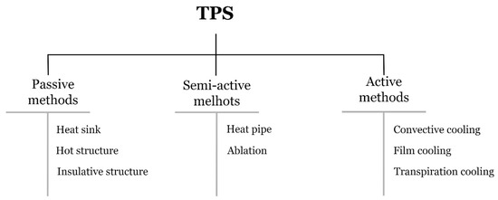
Figure 1. TPS classification based on their working principle and developed structures of each method.
2.3. Thermal Barrier Coating (TBC)
Thermal Barrier Coating (TBC)
Thermal barrier coating (TBC) systems are generally explored to enhance energy durability and therefore the efficiency of hot components of aero-engines, gas turbines, and parts for combustion power plants. Thus, TBCs protect the substrate structure by preventing them from experiencing high temperatures and harsh environmental degradation. Consequently, thermal barrier coating, as a surface modification technique, provides resistance to wear, oxidation, thermal shock, and corrosion for prolonged service times and thermal cycles without failure, increasing both the efficiency and lifetime of the desired components [24][25][26]. Ultimately, TBCs are multifunctional systems that provide a wide range of benefits, such as [27]:Thermal barrier coating (TBC) systems are generally explored to enhance energy durability and therefore the efficiency of hot components of aero-engines, gas turbines, and parts for combustion power plants. Thus, TBCs protect the substrate structure by preventing them from experiencing high temperatures and harsh environmental degradation. Consequently, thermal barrier coating, as a surface modification technique, provides resistance to wear, oxidation, thermal shock, and corrosion for prolonged service times and thermal cycles without failure, increasing both the efficiency and lifetime of the desired components [44–46]. Ultimately, TBCs are multifunctional systems that provide a wide range of benefits, such as [47]:
- shielding of metallic structure,
- decreased thermal conductivity,
- high thermomechanical stability,
- increased exhaust gas temperature,
- increased engine power efficiency,
- decreased fuel consumption, and
- increased lifespan of parts through decreased fatigue and stress.
The concept of “thermal barrier coating” is believed to have been first introduced by the National Advisory Committee for Aeronautics (NACA) and the National Bureau of Standards (NBS) with the publication of the earliest turbine blade-oriented ceramic coatings research entitled “Review of an Investigation of Ceramic Coatings for Metallic Turbine Parts and Other High–Temperature Applications” by W.N. Harrison, D.G. Moore, and J.C. Richmond in 1947 [48–50]. The pioneer ceramic coatings for aerospace applications were frit enamels used in aircraft engines throughout the 1950s [50]. With the development of the flame-sprayed ceramic coating technique, further applications included the protection of sheet metal in jet engines and rocket engine thrust chambers. With regard to the materials appraised for TBC purposes, flame-sprayed zirconia-calcia coatings were widely applied to the regeneratively cooled XLR99 thrust chamber for the X-15 experimental rocket planes. In addition, “modern” plasma-sprayed TBCs began to be employed on hot section transition ducts and other hot section sheet metal components in commercial gas turbines in 1970 [51]. Most recently, the microstructure of thermal barrier coatings, the materials applied, the coating preparation technologies, and the failure mechanisms, as well as lifetime prediction models, have all been part of the different branches of extensive investigation [48].
-
shielding of metallic structure,
-
decreased thermal conductivity,
-
high thermomechanical stability,
-
increased exhaust gas temperature,
-
increased engine power efficiency,
-
decreased fuel consumption, and
-
increased lifespan of parts through decreased fatigue and stress.