Your browser does not fully support modern features. Please upgrade for a smoother experience.
Please note this is a comparison between Version 1 by Diptish Saha and Version 2 by Sirius Huang.
Several issues of individual microgrids (MGs) such as voltage and frequency fluctuations mainly due to the intermittent nature of renewable energy sources’ (RESs) power production can be mitigated by interconnecting multiple MGs and forming a multi-microgrid (MMG) system. MMG systems improve the reliability and resiliency of power systems, increase RESs’ utilization, and provide cost-efficient power to the consumers.
- microgrid cluster
- energy management system
- multi-microgrid architectures
1. Introduction
In recent years, the electricity grids have undergone a big transformation due to the integration of a large number of distributed energy resources (DERs). Since the power from renewable-based DERs is highly dependent on environmental factors such as solar irradiance, ambient temperature, and wind velocity, energy storage systems (ESSs) such as batteries are commonly deployed to smooth out power fluctuations [1][2][3,4]. According to the U.S. Department of Energy, an MG is defined as a group of interconnected loads and DERs within clearly defined electrical boundaries that acts as a single controllable entity with respect to the grid. An MG can connect and disconnect from the grid to enable it to operate in both grid-connected and islanded modes [3][5]. Standalone MGs can provide power to rural areas, and off-grid systems, where it is either difficult, expensive, or impossible to establish a connection with the main power system. Some examples are electric ships [4][5][6][6,7,8], more electric aircraft [7][8][9][10][9,10,11,12], space MGs, and satellite systems [11][13].
The conventional grid is a central power dispatch system where large power generation systems supply the loads through long power transmission and distribution lines. The central power generation makes the dispatch system unreliable as any disturbance or fault might result in the disconnection of many critical loads. Upon the introduction of the MG concept, the conventional power system will be transformed into a distributed and more flexible power system, where MGs can be automatically isolated from the main grid to prevent propagating disturbance or affecting the normal operation of other parts of the system. However, these self-governing distributed systems demand the development of an advanced control system. The control of MGs consists of the control of power converters, power-sharing among the distributed generator (DG) units, controlling the voltage and frequency (at the point of common coupling (PCC)) for grid-connected MGs, and charging and discharging of ESSs, among others. Furthermore, the MG controller has to be intelligent enough to make decisions about the switch over from (to) islanded to (from) grid-connected modes of operation. A significant amount of work has been performed by researchers to establish the required control infrastructure for the operation of MGs. The control of different types of power converters for coordinating the smooth operation of an MG is discussed in [12][14]. The optimal operation of an MG is achieved in [13][15] by optimizing the usage of DG units and power exchange with the main grid. In [14][16], load balance among three phases of a four-wire MG is maintained using single-phase converters connected among the phases. In grid-connected mode, the voltage and frequency of the MG are dictated by the main grid and maintained within the permissible range [15][17]. On the other hand, islanded MGs become vulnerable to blackouts due to the fluctuations in power from RESs and loads, thereby voltage and frequency disturbances [15][17]. Droop-based coordinated control of the RESs and ESSs is discussed in [16][17][18,19]. Other aspects of MG control are addressed in [18][19][20][21][22][20,21,22,23,24].
The reduced number of synchronous generators and the massive incorporation of inverter-based RESs resulted in the reduced inertia of power systems [23][25] and the instability and vulnerability of MGs. To resolve these issues, instead of always connecting an MG to the main grid, the interconnection of MGs as a multi-microgrid (MMG) network is suggested as a promising solution to enhance the stability and power quality of the power system [2][23][24][4,25,26]. The Interconnection of MGs to form an MMG system facilitates more-efficient energy utilization, especially renewable energy, through sharing of resources among MGs [2][4]. As a result, the reliability of individual MGs and the entire power system will be increased. The connections among MGs can be also altered to further improve the reliability and stability of MGs [23][25][25,27]. However, there are practical challenges that need to be appropriately dealt with. The MMG concept also enhances the resiliency of MGs. In the case of low-probability, high-impact extreme events such as natural disasters, an MMG system is capable of supporting the operation of the main grid, as well as its MGs to maintain their main functionalities. If the power source of an MG is lost, other MGs can supply the critical loads of the damaged MG for a while or until the damaged MG is restored to normal operation [2][23][4,25]. Furthermore, from a top-down point of view, in case the electricity system is undergoing a faulty operation, the functional sections of the grid can be sectionalized to restore the electricity supply. The sectionalized system can act as an MMG by synchronizing different sections for coordinated operation [23][25]. In an MMG system, the interconnection of closely located MGs can reduce the power transmission distances and, thereby, the power losses. The reduced transmission losses and more-efficient utilization of power resources through power sharing can help to provide more cost-efficient power to consumers. MGs in an MMG system might be of various types such as residential, commercial, or industrial MGs with different load profiles. The complementary nature of the generation and load profiles of MGs in an MMG system can support their efficient collaboration and power sharing, thereby enhancing RESs utilization [2][4]. Along with the many benefits provided by MMGs, various challenges and complexities are involved, which can be classified into operation management, control, protection, and communication issues. As there might be multiple stakeholders and mixed ownership in an MMG system, data privacy and financial issues might also impose new challenges. In addition, the interoperability of multi-vendor controllers and standardization process difficulties need to be addressed [2][23][4,25].
2. Multi-Microgrid Architectures
There are different ways in which MGs can be connected to form an MMG system. While in a single MG, RESs, ESSs, and loads are connected to a single PCC, MMGs have multiple PCC and PCC locations. Different names are also used for MMGs including nested MGs [23][25], networked MGs [2][4], interconnected MGs [26][28], and coupled MGs [24][26]. However, all of them convey the same concept of interconnecting single MGs with each other.
The most-common way of forming an MMG system is directly connecting the MGs to the main grid. In this architecture, different MGs are directly connected to the main grid, and there is no direct power line among MGs. This architecture is in the form of a star and is known as a radial topology [26][28] and parallel-connected MGs with an external grid [1][3], as shown in Figure 1a. In the grid-connected mode, the EMS is comparatively simple to implement as there is only one single power line connecting the MGs to the main grid. An MG with an energy surplus/shortage can sell/buy its energy to/from the main grid [26][28]. In case of any disturbance in the upstream network, MGs can disconnect from the main grid and switch to the islanded mode. However, there will also be no connection to other MGs [1][3]. Expanding and connecting new MGs to this architecture is relatively straightforward, if the MMG control and communication system can support new MGs. As there are no direct power lines among the MGs, the energy exchange takes place through the main grid power line. Hence, the main grid power line should have the required capacity to support the power flow to an MG and also in between the MGs. Sharing of energy among the MGs in this architecture may create power congestion and thermal stress in the power line of the main grid. The operator has to ensure the safe operation and maintain the reliability of the network buses and the main grid [26][28].
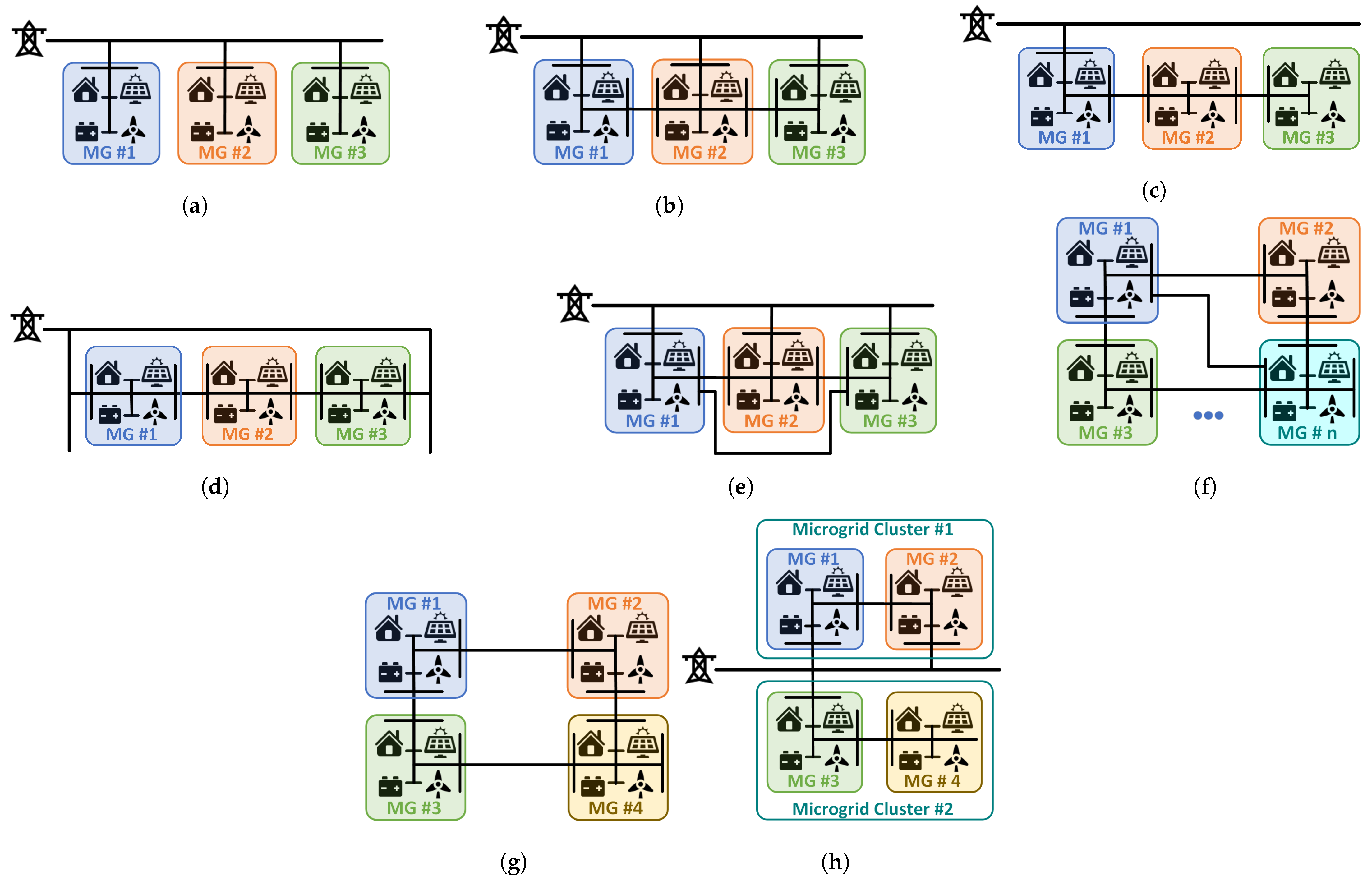
Figure 1. Different architectures of MMGs. (a) Radial topology [26][28], parallel-connected MGs with an external grid [1][3]. (b) Daisy-chain topology [26][28]. (c) Serial MGs on a single distribution feeder [2][4]. (d) Interconnected MGs on multiple distribution feeders [2][4] (e) Mesh topology [26][28]. (f) Grid series-interconnected MGs [1][3]. (g) Ring formation [1][3]. (h) Mixed parallel-series connection [1][3].
To have a direct power exchange capability between the MGs, along with their connection to the main grid, the adjacent MGs are directly connected in a daisy-chain topology [26][28], as shown in Figure 1b. This topology enables an MG to exchange power with the adjacent MGs (in the case it is allowed by the system regulators), in addition to the main grid, which increases the reliability of the MMG system. However, the technical challenges of coordinating different MGs need to be addressed. A similar topology named parallel MGs on a single distribution feeder is discussed in [2][4], where two adjacent MGs are connected by an exclusive power line and are also connected to the main grid. Among several serially connected MGs, if only one of them is connected to the main grid, the architecture is called a serial MG on a single distribution feeder [2][4], as shown in Figure 1c. Moreover, in an interconnected MG on multiple distribution feeders architecture, serially interconnected MGs are separately connected to different distribution feeders, as shown in Figure 1d [2][4]. The implementation of EMS is comparatively complex in these architectures as the power can be transferred from both the main grid and the neighboring MGs [26][28]. These MMG architectures have various operating switches, so the configuration of the MMG and MMG clusters can change dynamically [2][4]. Therefore, the EMS may have to consider several architectures while scheduling the energy exchange for the stability of the MMG and the grid [2][4]. The MGs’ operations in these MMGs are strongly coupled, and their energy schedules are more connected [26][28]. These MMG architectures are more reliable than the radial topology as the MGs will have several alternatives for power exchange in case of faults or natural calamities.
To further increase the energy exchange capability among MGs in an MMG system, all MGs in a radial topology are connected by direct power lines, as can be seen in Figure 1e, which is called a mesh topology [26][28]. A similar topology named grid series interconnected MGs [1][3] (Figure 1f) is also introduced in which “n” MGs can be interconnected. This MMG system must maintain the required voltage and frequency, as it is not connected to an external grid. In this topology, the faulty section of the MMG system can be disconnected, and external support to the sub-clusters in the MMG system is not completely lost. Therefore, this topology can have better performance during the off-grid operation mode. Instead of connecting all the MGs, the MGs can also be connected to form a ring, as shown in Figure 1g, which is called ring formation [1][3]. In this architecture, the power exchange between two MGs may take place through inter-mediator MGs, and the power line connecting the MGs must be capable of transferring the required energy. In [1][3], a topology named mixed parallel-series connection (Figure 1h) is presented, which is a combination of parallel MGs on a single distribution feeder and serial MGs on a single distribution feeder [2][4]. In this topology, there is the possibility of power exchange among the connected MGs if the MMG is not connected to the main grid. The MMGs that can operate in both grid-connected and islanded modes can form a cluster of MGs, which are called MG clusters [1][3], as shown in Figure 1h. These MG clusters have at least one connection to the main grid [1][3] and can connect to the main grid at the time of need. In the mesh topology [26][28], and grid series-interconnected MGs [1][3], the reliability of the MMG system increases due to the ability of direct power exchange between the MGs, but at the expense of the increased establishment cost of power lines and control complexity. However, there is the risk of fault propagation among MGs. Thus, a trade-off can be made between reliability, establishment cost, and control complexity. In the mesh architecture, the MMG system can disconnect faulty MGs to restrict the voltage–frequency-related disturbances to the faulty MG and ensure the reliable operation of the rest of the MG cluster.
It is worth mentioning that the MMG system does not always maintain the same architecture, but rather, the MMG architecture encounters frequent changes due to the connection and disconnection of MGs from the MMG system or the MG cluster from the main grid. These connections and disconnections are due to disturbances or support the MGs’ needs in an MMG system. In this sense, advanced robust control techniques are required to establish energy management, power sharing, disturbance and fault handling, and uncertainty mitigation in MMGs. Table 1 presents a review of the commonly used MMG architectures.
Table 1.
Review of MMG architectures reported in the literature.
| MMG Architecture | Ref. |
|---|---|
| Radial | [27][28][29][30][31][32][,31][33]57][,32[58,33,3434,35][35][36,36][37][38][39][40][41][42][43][44][45][,3746][,38][47][48][49][50][51][52][53][54][55][59][,3960,40,41,42,43,44][,4561][,4662,47,48,49,50,51,52,53,54,5556,56,57,58,59,60,61][63][64][65][66][67][68][69][70][71][72][,6273,63],64[74][75][76][77],65[,6678,67][79][80][81][29,30,68,69,70,71,72,73,74,75,76,77,78,79,80,81,82,83] |
| Daisy-chain | [82][83][84,85] |
| Mesh | [84][85][86][86[,8787,88],89] |
| Ring | [78][88][89][90][91][92][93][94][80,90,91,92,93,94,95,96] |
| Serial | [95][96][97,98] |
| Mixed parallel-series connection | [97][98][99][100][99,100,101,102] |
| Serial MGs on a single distribution feeder | [101][102][103,104] |
| Parallel MGs on a single distribution feeder | [103][105] |
| Interconnected MGs on multiple distribution feeders | [104][106] |
3. AC, DC, and Hybrid AC–DC Interconnection Technologies
Different MMG architectures are depending on the line and interconnection technologies [1][3]. The line technology of an MMG system can be AC, DC, or AC–DC [1][3]. The AC transmission and distribution system is a very mature technology and is widely used in residential, commercial, and industrial areas. Over the years, AC three-phase systems have shown a higher efficiency and lower cost compared to single-phase systems [1][3]. Load sharing among MGs in an AC MMG system is discussed in [41][89][43,91]. On the other hand, DC MGs eliminate synchronization problems, the usage of bulky transformers, and harmonic and power quality issues while facilitating the parallel operation of DERs. In the case of offshore renewable energy technology such as offshore wind farms, high voltage DC (HVDC) transmission is widely used [1][3]. DC MGs are interconnected to form DC MG clusters in [105][107], and their stability is analyzed considering the effect of constant power loads and interconnecting line impedance. Load sharing with voltage improvement of two interconnected DC MGs is discussed in [106][108]. Energy exchange in a DC energy network connecting multiple houses is investigated in [107][109] using a peer-to-peer architecture. A fast fault detection–protection scheme with simultaneous control of interconnected DC MGs is designed in [108][110]. To exploit the benefits of both AC and DC technologies, various hybrid AC–DC MGs are also investigated by researchers. The EMS and optimal scheduling strategy of a hybrid AC–DC MMG system are discussed in [91][109][93,111], respectively.
Regarding the interconnection technology, the authors of [1][3] classify the MMG architectures based on the interconnection of MMGs using either conventional power transformers or power converters. A conventional power transformer can be used to interconnect two AC MGs, while a power converter must be used in the case of interconnecting a hybrid MG. Power transformers are more reliable and less expensive than power converters and provide electrical isolation. However, power transformers are less controllable for the energy and power-sharing requirements of an MMG system [1][3]. In this case, the power exchange between the MGs or an MG and the main grid cannot be directly controlled. Power exchange takes place depending on the generated power of the MGs or the main grid at the PCC [41][43]. Furthermore, the voltage and frequency of one MG may be dictated by the main grid or other MGs [41][43]. Hence, the MG becomes vulnerable to disturbances at the main grid or other MGs. On the other hand, power electronic converters are more expensive, but provide higher flexibility for the control and power management of MMGs [1][3]. The MG’s controller can send control signals to the local interconnecting power converters for appropriate power exchange, thereby providing the capability to regulate power generation and power exchange independently in an MG [41][43]. Solid-state transformers or isolated converters can provide the required electrical isolation while using power converters for interconnecting MGs.