Your browser does not fully support modern features. Please upgrade for a smoother experience.
Please note this is a comparison between Version 1 by KASHAN KHAN and Version 2 by Rita Xu.
Compared to traditional onsite steel construction, prefabricated industrial steel construction (PFISC) saves time, money, and resources. It results in sustainable steel structures that use fewer resources and are better for the environment.
Compared to traditional onsite steel construction, prefabricated industrial steel construction (PFISC) saves time, money, and resources. It results in sustainable steel structures that use fewer resources and are better for the environment.
- prefabricated industrial steel buildings
- automated and detachable IMCs
- vertical and horizontal diaphragm continuity IMCs
- foundation fixity systems
1. Introduction
Compared to traditional construction, prefabricated industrial construction (PFIC) has recently increased in its importance for modern urbanization. This is because of energy consumption, global expectations, green building, and outstanding structural performance [1][2][3][1,2,3]. It has relied on the industrialization of parts or finished rooms transported and installed using simple connections, as shown in Figure 1 [4][5][6][7][8][4,5,6,7,8]. It is widely used in emergencies and repetitive construction projects, such as dwellings, military housing, dorms, clinics, and classrooms [9][10][11][9,10,11]. This has already been introduced in China, the United Kingdom, Japan, Korea, Australia, Germany, the Netherlands, and the United States [1][11][12][13][14][15][16][17][1,11,12,13,14,15,16,17]. The UK’s housing industry attempted to accommodate 25% of housing societies, and China’s central and regional governments considered 30–50% with a 2–3% annual increase until 2026 [1][18][1,18]. This is sufficient evidence that PFIC is more efficient than the conventional techniques and is essential to meet the housing demand.
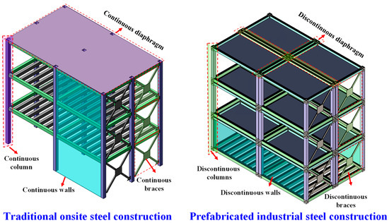
Figure 1. Traditional onsite vs. prefabricated industrial steel construction.
Materials used in PFIC are usually the same as onsite construction, but the components are manufactured under regulated conditions, resulting in better quality industrial modular units (IMUs). However, lightweight materials are always preferred for easy handling, assembly, and transport. Among the materials used in PFIC are steel, concrete, timber, and aluminum. Although aluminum IMUs are lighter, 1.5 times stronger, and have tighter tolerances than steel IMUs, their brittleness and high price remain significant barriers [19]. Timber is often used in low-rise PFIC, whereas steel and concrete have historically been the standard for high-rise PFIC. Steel is preferred over concrete since it is 25–30% lighter, more resilient, and requires fewer joints [20]. Timber necessitates polishing onsite, while concrete demands an accessible base to minimize the self-weight. On the other hand, steel is robust and stiff enough not to be oversized or downsized to obtain prefabricated industrial steel buildings (PFISBs). This inherent strength enables IMUs to withstand oscillations during shipping without requiring support, resulting in reduced transport costs compared to other conventional materials [6]. Including its inherent strength, steel’s structural stability, notably its strength against dynamic loads, increases its preference as a material in high-rise PFISBs, revealing itself to be more affordable than concrete structures. Thus, steel is a favored material choice among architects for high-rise PFISBs [21].
Prefabricated industrial construction displayed an exceptional quality, efficiency, productivity, and versatility. It proved to have shorter project durations, lower overall costs, and the less wastefulness of resources [22]. Therefore, it possesses the potential of a sustainable construction method [23]. Lawson et al. [24] reported an improved sustainability by reducing the construction waste from 10–15%, site visits to 70%, site disruption or noise pollution from 30–50%, and onsite accidents above 80%. Additionally, it was found to lower the environmental impacts by reducing the material wastage to 64%, greenhouse gas emissions to 40% [25], and economic implications by reducing the production hours to 31% [26]. A comparative study concludes that a reduction in the economic impact can be achieved by saving 60% of steel, 77% of the framework [27], and reducing the resource depletion to 36%, a social influence by limiting the health damage to 6.6%, the environmental impact by reducing the ecosystem damage to 3.5%, and economic implications by the reduction in the energy consumption to 20% [28]. It can be concluded that PFIC can increase the productivity, efficiency, and safety while decreasing the number of onsite visits, transport activities, material wastage, noise pollution, energy consumption, hazardous gas emissions, and reliance on unskilled labor. The critical advantage originates from its quick fabrication; this can reduce the construction time by 30–50% compared to conventional construction. In China, broad sustainable building (BSB) was pioneered with the T30 tower [29] in 15 days and the J57 tower [30] in 19 days. The 60-story Collins house, 44-story Atira student accommodation, and La Trobe towers in Australia are the tallest panelized PFISB skyscrapers [31]. The 44-story Croydon tower [32], 32-story B2 tower [33], 29-story Apex [34], and SOHO tower [35] are high-rise volumetric PFISB skyscrapers using PFIC. By developing the two fastest temporary hospitals, i.e., Huoshenshan and Leishenshan, within 6–10 days in Wuhan, China, the PFIC method has fully achieved its goal of being an environmentally friendly, speedy, and dynamic form of construction [36][37][36,37].
2. Technological Advancements
2.1. 2D to 3D Assembling Techniques
Prefabricated industrial steel constructions have become increasingly popular recently. They are used in the construction of low-rise structures as well as high-rise PFISB skyscrapers. A Hickory Building System (HBS), consisting of panelized systems to build PFISBs, such as load-bearing walls, concrete floors, and facades, involves integrating and assembling 2D panels onsite to form 3D IMUs through wet joints. The 44-story Atira student accommodation, 60-story Collins house, and 44-story La Trobe towers in Australia used HBS technology [31]. With 80–95% factory-based fabrication, 3D IMUs can be recognized as mobile homes [38][44]. The 44-story Croydon tower [32], 32-story B2 tower [33], 29-story Apex [34], and SOHO tower [35] used the completely finished 3D IMU. Before moving to the site, the 3D IMU is always fully serviced and prefinished in the factory. HBS systems, on the other hand, are less sustainable because they require an onsite finish and assembly, increasing the complexity and onsite working, reducing the construction productivity. However, compared to traditional steel construction, both panelized and volumetric PFISBs could reduce the construction time by more than 30–50%.2.2. Industrial Modular Units Forms
Prefabricated industrial steel buildings are classified as continuous and corner-supported [39][40][45,46]. Walls which guard continuous supported PFISBs, such as lightweight walls and a hybrid module–barrel system, are developed. The sides of the lightweight wall PFISB are supported by light C-section members that are only suitable for low-rise structures [41][42][47,48]. Since they are composed of SHS and can withstand vertical and lateral stresses, the PFISB module–barrel hybrid system, on the other hand, can be employed in high-rise structures [39][41][42][43][45,47,48,49]. Corner columns in corner-supported PFISB structures principally resist the load. Light and heavy steel IMUs are the corner-supported PFISB. ATLS is a lightweight PFISB that can be built and dismantled multiple times using open, thin-walled, cold-formed sections. They are favored in low-rise structures since their weak connection leads to a minimal structural integrity [44][50]. SHS columns welded with SHS beams support heavy steel IMUs. Such IMUs are utilized in high-rise PFISBs because of the high bending resistance, lateral–torsional, torsional, and compression of the columns and beams [45][46][51,52]. In conclusion, continuous supported module–barrel hybrid PFISB has increased the in-plane rigidity and lateral stability [47][53]. They have an excellent lateral and longitudinal stability compared to heavyweight corner-supported PFISBs due to load sharing across several columns, making them better suited for high-rise PFISBs [39][45].2.3. Manual to Automatic Non-Detachable Inter-Modular Connections
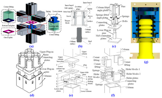
For manually operating PFISBs, inter-modular connections (IMCs) that are welded, bolted, and prestressed are frequently used, as shown in Figure 2a–f. While all of these IMCs have been demonstrated to have an adequate seismic resistance in pertinent investigations, they do have challenges. Due to the extensive onsite work of the welded IMCs, there is not enough room for MEP services, a secure weld quality, and full welding [48][54]. Welded connections were the most common type of IMC studied by Annan et al. [10][48][49][50][10,54,55,56] that exhibited a satisfactory performance; nevertheless, they are costly, of a poor quality, and require functional space for internal connection welding [51][57]. As depicted in Figure 2a, welding connections are avoided due to the aforementioned difficulties; hence, bolted connections are chosen on the construction site [48][52][38,54]. Bolted IMCs have strict operational space requirements and a lower production efficiency [53][58]. Doh et al. [54][59] discovered that bolted bracket connections were susceptible to prying failure, exhibiting a brittle behavior and are suited for low-rise structures. Thus, Chen et al. [55][56][60,61] developed rotary connectors that protect the columns; access holes are used for large bolt tightening, as displayed in Figure 2b [57][62]. The experiments demonstrated an outstanding bearing capacity and ductility in high-rise PFISB extreme dynamic situations [58][63]. Plug-in supported joints are developed which can fully assemble interior IMUs, and their seismic performance has been studied, such as the beam and column bolted IMC in Figure 2d [59][64]; fully bolted IMC in Figure 2e [60][65]; and beam bolted IMC in Figure 2c [61][62][66,67]. They demonstrated a superior ductility, energy dissipation, plastic deformation, and bearing capacity, whereas the weld of the intra-modular joint fractured; nonetheless, the failure was transmitted to the column. The building regulations for the prestressed IMC are stricter and more complicated. Prestressed rebars can join columns vertically, but their limited moment-resistance capability makes them unsuitable for high-rise buildings because superimposed forces can cause elevating and joint failure [63][40]. In order to achieve the composite prestressed joint shown in Figure 2f, the columns are filled with concrete. This joint effectively transfers medium-level lateral forces in a ductile manner due to the contact bond between the concrete, plug-in, strands, and shear bloc; however, a significant bond reduction can cause concrete crushing, a gap formation, strength, and stiffness degradation [64][65][68,69]. Workers may also bolt or weld the corners and exterior interface from the outside. The IMUs’ wall panels and slabs, particularly the installation, do not have the necessary construction clearance for the internal IMC. Some IMCs do not make the final IMU tighter. Others, on the other hand, prefer to make holes in order to assemble them, which may compromise the IMUs’ sectional integrity and interior design. In order to address the problems above, various automatic IMCs that require no functioning space have recently been developed, as shown in Figure 3a–g. The researchers designed a sliding bloc IMC that joins the IMU via a self-locking setup, as shown in Figure 3a [51][57]. The joining method resembles the lock-tongue joint in Figure 3f in appearance [66][70]. Another investigation also created the self-locking slider joint displayed in Figure 3e which works similarly with the joins in Figure 3a,f [67][71]. The top movable panel and springs are attached to the side of the bottom IMU column, and the plug is attached to the base of the upper IMU column. As a result, the connector is fixed, the slider panels move laterally during the mounting of the IMU, and a slip forms between the top and bottom segments of the plug. Self-locking connections’ hysteresis behavior featured plumper hysteretic rings and worked well in seismic tests. Since their initial stiffnesses were comparable to those of the welding connection, they were just as dependable as the welding IMC. The problem with these connections was that they only fixed two sides by locking sliders on two sides, leaving the other sides loose or unsupported, which made them weaker in earthquake-prone areas. Therefore, to achieve the fixity of the tubes and IMC in opposite and neighboring four sides, researchers developed pin-type joints, as shown in Figure 3c [68][72], and plug-in type joints, as shown in Figure 3d [69][73], inserted inside columns, which further improved their seismic performance and made them suitable for mid- to high-rise PFISBs. Other researchers, such as Dai et al. [70][74] and Picard [71][75], depicted in Figure 3b,g, built an installation-friendly self-locking fastener machine by using springs and nuts and bolts to provide support around the bolt shaft. Their seismic performance shows that they behave as semi-rigid to rigid in high-seismic zones, making them suitable for usage in high-rise PFISBs. However, these self-locking IMCs ignore construction or deformation tolerances, which require a high degree of precision. Additionally, these IMCs cannot be removed once locked, making it challenging to reuse the IMU in the event of accidental damage during servicing.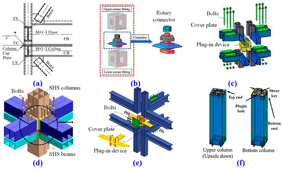
2.4. Manual to Automatic Detachable Inter-Modular Connections
Inter-modular connections cannot be removed once locked, making it challenging to reuse the IMU in the event of accidental damage during servicing. Because of this issue, researchers created bolted and pin types of IMCs through SHS, as shown in Figure 4a–d. They consider the constructional tolerance brought on by the automatic mechanical IMC and the repetitive use of IMUs via a replaceable or detachable IMC. The threaded block of the lower IMU is tightened to the bolt of the upper IMU using a long twisted rod that the researcheuthors designed for the detachable IMC shown in Figure 4a [66][70] and pinned joint shown in Figure 4d [72][76]. Although these joints are detachable, tightening the bolts inside the columns requires a lengthy rod tool, which is laborious; hence, the bolt diameter or screwing length is typically small, reducing their seismic and lifting capacities. Consequently, as shown in Figure 4b, a mechanical replacement has recently been developed to address these difficulties. A new, low-carbon mechanical IMC integrates the IMU horizontally and vertically through linearly translating the pins and transfer plates. An extended twisting rod is used in this connection to operate the mechanical arrangement of the components and pin them together [73][74][77,78]. As soon as the bolt is turned, horizontal pins instantly lock into place and establish a solid connection between the IMUs on the exterior and interior. These joints perform reliably in seismic and pullout operations. Because these bolted joints are only helpful in tightening or demounting corner and hollow columns, researchers created a new way to connect the beams rather than the columns without the need for any tightening equipment, as depicted in Figure 4c. The onsite fastening connections are replaced by a robust mechanical interconnecting system that allows for twist, tilt, and slide adjustments [75][79]. However, the joining system cannot withstand the tensile stresses, which forces the use of pricey adhesives and causes the uplift under extremely high lateral loads.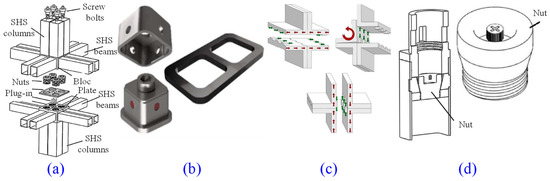
2.5. Lateral Loads Stabilizing Systems
Lateral stability systems are developed, including braces, shear walls, diaphragm walls, cores, base isolators, and viscoelastic dampers to resist the effect of lateral forces on high-rise PFISBs due to the incapability of the IMCs. As seen in Figure 5a–d and Figure 6a–f, IMCs have recently been invented. According to Sultana et al., superelastic self-centering SMA bracing and SMA bolts’ IMC minimizes the residual stresses and is a recyclable solution [76][77][80,81]. Through self-centering, the haunch bracing system proposed in Figure 6c improved the IMCs’ ductility [60][65]. Recently, a slider device with reusable bonded rubber units was devised [78][79][80][81][82][82,83,84,85,86]. After 5 mm of torsion and translation, they may dissipate 80% of the earthquake energy through friction. The haunch bracing with a plug-in IMC transferred the failure from the joints to the beams and demonstrated superior self-centering systems that may be used in high seismic zones for mid- to high-rise PFISBs. Moreover, the PFISBs’ and system’s full strength can be achieved using a double-skin steel shear wall, as shown in Figure 6b [83][87]. The composite action of the Corefast 2D and 3D walls increases the fire resistance while attempting to prevent the lateral force damage, as shown in Figure 6f [6]. This is a functional lateral force-resisting system because it delays the structure’s yield, increases the elastic stiffness with a yielding wall panel, and prevents out-of-plane buckling prematurely while causing column tearing and strength degradation due to local buckling [83][87]. However, the lateral stability offered by these stabilizing systems is limited because the upper and lower IMUs’ interconnectivity is lacking in regions other than the column corners. As per evaluation, the linked wall systems made up of numerous vertical bars and sleeves could aid structures with the superior lateral response, as shown in Figure 6d [84][88] and Figure 6e [85][89]. They rigidly connect vertical diaphragms using a composite connection between the walls using bars. Recently, one of the researcheuthors patented a base isolation technology, as shown in Figure 6a [86][90]. This satisfies the requirements for the standard use, structural bearing capacity, and an effective resistance to the effects of earthquakes. However, they are suitable for pre-tensioned and composite types of IMCs inside the columns of PFISBs. Therefore, other energy dissipation joints are developed; for instance, the researcheuthors invented a rubber isolation system [87][91] and a self-locking tenon-and-mortise vibration isolation rubber IMC in the IMU, as shown in Figure 5a,b [88][92]. The invention may reduce the adverse effects of earthquakes and improve the PFISB structure’s bearing capacity. Similarly, two distinct configurations of bolted IMCs having washer and resilient rubber layers are demonstrated, as shown in Figure 5d [89][93]. It has been shown that the IMCs which have been bolted are rigid and cause a column fracture, as opposed to the IMC in Figure 5d, which has been strengthened with resilient layers which can withstand significant deformations without fracturing the bolt [89][93]. A lead viscoelastic damper in a vertical IMC dissipated more energy than the conventional bolted IMC, such as those shown in Figure 3a–f and Figure 4a–d [90][94]. The damping joints in Figure 5a–d have the effect of delaying the premature failure of the structural components. They prevent a failure and collapse, increase the capacity, and guarantee security.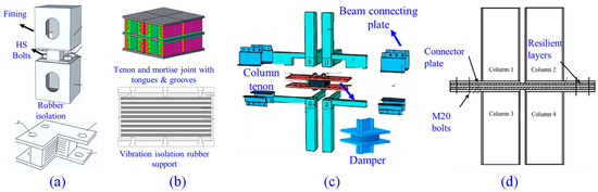
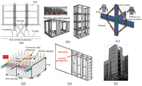
Figure 6. Lateral stabilizing units for a continuous vertical diaphragm. (a) base isolation system [86][90]; (b) double skin plate shear wall [83][87]; (c) haunch braces [60][65]; (d) hybrid coupled wall and diaphragm [84][88]; (e) light steel wall with concrete grouting [85][89]; and (f) 3D steel core system [6].
2.6. Top-Down Assembling Approach
The recently developed “Top-Down approach” involves building a structure from the top floor to the first floor [91][95]. The structural frame was designed with a hydraulic jack lifting system, eliminating the need for large cranes. The system can elevate the PFISBs’ structure while supporting the horizontal loads, minimizing swaying, and ensuring the structure’s integrity. Furthermore, it eliminates the need for scaffolding and cranes when operating at a height, improving the worker safety and reducing the time and labor expenses. The advantages include unloading, directly inserting the IMUs from the truck into the frame, and permitting working space around the cluster columns at the base. According to the frame type, this could be classified as essential or extended systems [92][96]. The frame is packed with a steel IMU created individually. Through the use of peripheral moment-frames, the lateral stability is enhanced.2.7. Vertical and Horizontal Diaphragm Continuity Systems
There were significant problems with the PFISBs’ in-plane stiffness and non-uniform lateral force transmission because of the discontinuity between the floor and wall diaphragms and no adequate connection system developed on the beams. In order to address the issues mentioned earlier, the researcheuthors most recently created a horizontal IMC using the tongues and grooves between the beams, as shown in Figure 7a [88][92]. Sharafi et al. [75][79] also designed a horizontal and vertical beam IMC that resists shear forces and provides a diaphragm continuity in both horizontal and vertical directions, as shown in Figure 7c. Both methods required expensive adhesives or a corner column–column IMC to fix because they could not withstand the uplift stresses. In order to offer horizontal and vertical diaphragm connectivity and an adequate lateral force resistance, the recent developments in the IMC, such as the wall-to-wall vertical shown in Figure 7d [93][97] and diaphragm-to-diaphragm horizontal IMC shown in Figure 7e [94][98], have been made. They had a sustainability challenge because extensive site work would be required. In order to accomplish a connection at diverse locations, another sustainable approach has been devised that uses field bolts to attach the IMU horizontally and vertically by welding angles to the beam flanges in both directions, as illustrated in Figure 7b [95][99].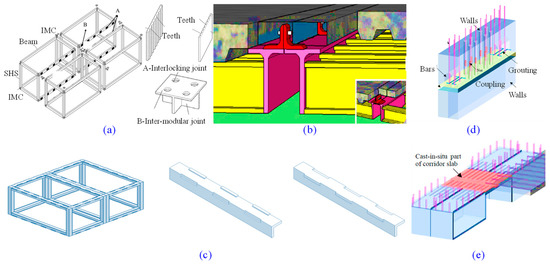
Figure 7. IMC for the continuous horizontal and vertical diaphragm. (a) beam-to-beam horizontal teeth lock [88][92]; (b) beam-to-beam vertical bolted clips [95][99]; (c) beam-to-beam horizontal and vertical sawed systems [75][79]; (d) wall-to-wall vertical cast-in situ rebars [93][97]; and (e) diaphragm-to-diaphragm horizontal cast-in situ rebars [94][98] IMC.
2.8. Automated and Robotized Systems
Due to the congested gaps between IMUs, fully finished 3D IMU-fitted PFISBs have difficulties installing MEP facilities. A single 3D file combining architectural, structural, and MEP data allowed for the effective implementation of the BIM to visualize and identify hundreds of conflicts between MEP and structural systems [96][100]. Additionally, to lessen the IMUs and component damage during transit, both structural and nonstructural. The conveyance of IMUs is planned, optimized, and visualized using the integrated BIM platform, Geographic Information System (GIS), and Vehicle Routing Problem (VRP) [97][101]. The system was discovered to track the environment, the network of roads, and the best route for the safe transfer of IMUs. The traditional manual techniques for configuring, choosing, and positioning the cranes remained dangerous; as a result, the Hevilift automated crane planning and optimization approach to effectively deploy thousands of cranes simultaneously has recently been implemented [98][102]. The robotized crane assembly with automation allowed the IMUs to be hoisted and installed with outstanding autopilot precision and safety, greatly enhancing the safety and sustainability of PFISBs [99][103].2.9. Foundation Fixity Systems
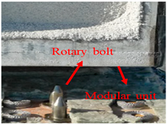
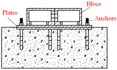
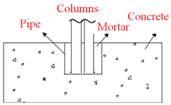
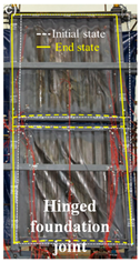
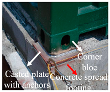
Due to the close proximity of the four columns in the PFISBs, they are more prone to sliding and overturning when subjected to high lateral loads; as a result, an adequate restraint is needed at the base. The appropriate foundations, such as the combine, raft, or pile foundations, can be adapted depending on the construction height and requirement to withstand the lateral load. Concrete spread footings are advised for small structures on good soil, mat foundations for large structures, and pile footings for soft soils, depending on the size of the structure, the type of soil, and economic considerations [100][104]. To fix the IMU by IMC blocs or IMU column base plate, as designed by several studies in Table 1, onsite casting, bolting to accessible onsite cast plates, or welding to accessible onsite cast plates can be used.Table 1. Foundation IMCs and relevant PFISB studies.
| Type | Detailing | Analysis | Features | |||
|---|---|---|---|---|---|---|
| Anchor IMC [10] |
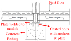 |
No reported studies on structural behavior evaluation | Suitable for high-rise PFISBs, with the ability to withstand uplift, shear stress, and moment owing to anchors cast onsite and welded to the base plate. | |||
| Anchor IMC [101] | Anchor IMC [105] |
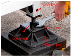 |
No reported studies on structural behavior evaluation | The anchor and plate can be welded to the rubber-pad footing and are suited for the low- to mid-rise PFISBs because it resists uplift, shear stress, and moment. | ||
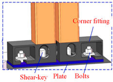
| Key IMC [101] | Key IMC [105] |
 |
No reported studies on structural behavior evaluation | Shear-key in the IMU can withstand shear force and a small moment but is dangerous when subjected to uplifting forces and is not suitable for high-rise PFISBs. | ||
| Anchor IMC [102] | Anchor IMC [106] |
 |
No reported studies on structural behavior evaluation | To resist uplift, shear force, and moment in high-rise PFISBs, the base plate is welded to the connecting plate that has been anchor-welded. | ||
| Stud IMC [103] | Stud IMC [107] |
 |
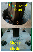 |
It can withstand uplift, shear stress, and moment and prevent uplifting while producing ductile failure, but it can also start brittle failure in high-rise PFISBs with infilled moment-frames. | ||
| Bolted IMC [55][[104] | Bolted IMC [60 | 56][58] | ,61,63,108] | 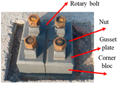 |
 |
They are effectively used in a five-story PFISB in China, where bolts are tightened onsite using nuts, preventing the IMU from rising and resisting uplift, shear strain, and severe moments. |
| Welded IMC [100] | Welded IMC [104] |
 |
No reported studies on structural behavior evaluation | The onsite welded plate has high stiffness and strength and can resist uplift, shear force, and moment. However, full welding is difficult; thus, best suited for mid-rise PFISBs. | ||
| Key IMC [105] | Key IMC [109] |
 |
No reported studies on structural behavior evaluation | Although onsite anchors are cast with shear keys and connecting plates, they can resist uplift, shear force, and moment; interior bolting presents a barrier. |