Your browser does not fully support modern features. Please upgrade for a smoother experience.
Please note this is a comparison between Version 1 by Farin Ramezani and Version 2 by Dean Liu.
The use of carbon fibre- reinforced polymer (CFRP) materials is increasing in many different industries, such as those operating in the aviation, marine, and automotive sectors. In these applications, composite parts are often joined with other composite or metallic parts, where adhesive bonding plays a key role.
- composite materials
- adhesively bonded joints
- carbon fibre reinforced polymers
1. Joint Geometry
The mechanical performance of a bonded joint is known to be highly dependent on joint geometry, which includes factors such as overlap length, adherend and adhesive thickness, etc. Among the most significant of these parameters are the overlap length (l), adherend thickness (T), adhesive thickness (t) and the adherend and adhesive elastic modulus and shear strength [1][40]. Figure 1 presents a schematic design of a single lap joint, illustrating the aforementioned parameters.
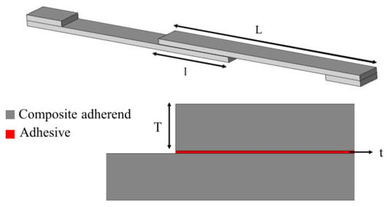
Figure 1. Schematic design of a single lap joint.
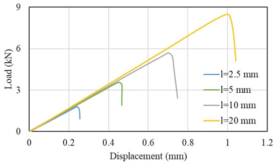
Multiple research studies have been carried out to understand the effect of the overlap length in composite joints. It can be generally stated that, if the adherend does not fail or yield, an increase in the overlap length will lead to an increase in the failure load of the joint. This is known to occur even under different loading conditions e.g., under quasi-static and impact loads (see Figure 2) [2][3][4][41,42,43].
This increase in the failure load could be explained by the substantial effect that the overlap length has on the peel stress, a fact shown numerically by Demiral and Kadioglu [6][7][45,46]. At the same time, the failure load is also highly affected by the applied strain rate in composite joints, a result of the strain rate sensitivity exhibited by the adhesive and the polymeric resin of composites [2][5][41,44].
However, if stiff and brittle adhesives are used, an increase in the overlap length will result in a more modest (or even a negligible) increase of the failure load, which is in contrast to that found for joints bonded with a ductile adhesive, where the increase in failure load is found to be almost directly proportional to the increase in overlap length. This can be explained by the fact that severe stress concentrations are generated at the overlap ends by the stiff and brittle adhesive, leading to premature failure. These stress concentrations are present even for very large overlap length values, reducing the effectiveness of increasing this dimensional parameter.
Li et al. [8][47] presented a thorough experimental study on the effect of adherend thickness for single lap, double lap and scarf composite joints, where a higher failure load was observed for all the mentioned configurations in larger adherend thicknesses (higher strength for single and double lap joints, but lower strength for scarf joints). In the case of scarf joints, the authors [8][47] showed that by increasing the scarf angle a higher lap shear strength was obtained.
2. Effect of Surface Preparation
To ensure maximum joint strength, the bonding surfaces must be thoroughly prepared before the adhesive application, which is often a costly and time-consuming process, but essential to avoid adhesive failure. Furthermore, bond strength and durability are known to be extremely sensitive to environmental parameters such as the temperature and humidity, both of which can have a deleterious effect on the adhesive/adherend interface and degrade the level of adhesion.
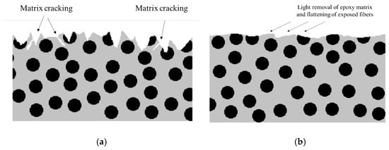
A proper surface treatment for composite adherends should always seek the removal of all contaminants from the surfaces and ensure a good level of adhesion, which can be achieved through an increase of wettability (increasing surface energy and the chemical activation of material surfaces being bonded) or by increasing the roughness of the surface (and increasing the level of mechanical interlocking between the adhesive and the adherend) [9][10][11][48,49,50]. Many different chemical and physical surface treatments are currently available for composites. These employ different methodologies, such as mechanical abrasion [12][51], degreasing the surface with solvent [13][14][52,53], laser ablation [15][16][54,55], plasma treatment [17][18][56,57], peel ply technique [18][19][20][21][22][57,58,59,60,61], irradiation [23][62], grit blasting [24][25][63,64] and chemical surface activation [26][65]. It is important to take into account the fact that the bulk mechanical properties of a composite can be strongly affected by surface treatments. For example, severe abrasive treatments can damage the composite and adversely affect joint behaviour [27][28][66,67] and bond strength [29][30][68,69]. This is because the fibres closer to the surface can be damaged by abrasion, reducing composite strength and the adhesion of the fibres to the matrix, and may even introduce contamination through loose microparticles (see Figure 3) [31][70]. Nonetheless, microparticles can be removed with the use of suitable high-power ultrasonic cleaning methods, and, hence, the use of primer coating together with high-power ultrasonic cleaning leads to a significant increase in strength [32][71].
Laser surface treatment is an eco-friendly and non-contact procedure which dispenses with harmful chemical solutions and does not introduce secondary contaminations. This method can be used to provide greater roughness and wettability, leading to higher shear strength and a cohesive failure mode when compared with conventional mechanical abrasion [12][34][51,73]. It has also been shown that aging does not significantly degrade the quality of the laser-treated interface [15][54]. The use of this approach is well suited for the preparation of composite adherends [35][74], although there is still some possibility of local fibre damage with high accumulated laser fluence [36][75].
The use of peel ply is a commonly used technique to protect the surface of composite laminates from contamination, while also creating and maintaining a specific surface texture [20][59]. A peel ply layer is used to absorb any residual resin and to create an activated surface for adhesive bonding or coating by peel ply removal. This method is also able to provide a good surface treatment for bonding purposes.
Different methods are available to assess the pre-bond quality of CFRP surfaces. One of these is the optically stimulated electron emission (OSEE) [37][76], able to detect weak adhesive bonds of CFRP [38][77], which might have been caused by contamination or poor curing of the adhesive. Other methods can be used to detect defects in the laminate itself, such as the use of electromechanical impedance [39][78], acoustic emission [40][79] or ultrasonic emission [41][80], or the electrical resistance method [42][43][44][45][13,81,82,83]. However, interfacial defects in the form of kissing bonds may still go undetected. Attempts using advanced ultrasonic methods such as nonlinear ultrasounds, guided waves or digital image correlation (DIC) [46][84] inspection to detect kissing bonds have met with limited success. However, some authors report that DIC can be effective when applied in the case of partial or localized kissing bonds [46][84].
3. Effect of Manufacturing Process
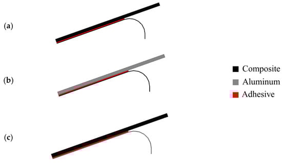
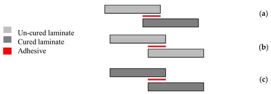
The manufacturing process of composite joints can follow three different approaches, the selection of which can be dependent on the nature of the composite and adhesive, and their curing temperatures. These processes are known as co-curing, co-bonding and the secondary bonding method [47][38]. A co-bonding process is performed when one adherend is cured simultaneously with the adhesive, while in the co-curing process both adherends and the adhesive are simultaneously cured. Secondary bonding is when the adhesive layer is cured between two pre-cured composite substrates [34][47][48][38,73,85]. Figure 4 shows a schematic design of the mentioned manufacturing methods.
Each of these manufacturing methods is known to have its own specific advantages and disadvantages [49][86]. For secondary bonded joints, failure is known to occur in the composite [50][87] and edge effects are not so predominant [51][22]. On the other hand, in co-bonded joints, failure typically occurs in the adhesive, since greater resistance to crack initiation and propagation has been observed [50][87] and significant edge effects have been observed [51][22]. However, the co-bonded joints have been shown to have a lower strength than the secondary bonded joints under a wide range of loading conditions [52][53][54][55][88,89,90,91]. In some cases, the moisture present in the prepreg was found to have been released during curing and had migrated to the adhesive layer, which led to a weakening of the interface and lower strength of the co-cured joints [54][56][90,92].
Notwithstanding, co-curing or co-bonding methods are usually preferred over the secondary bonding methods, because the number of parts and curing cycles needed are reduced. Hence, secondary bonding is mostly used for the repair of composite structures while for large and complex structures the secondary bonding process is more suitable [47][57][38,93].
4. Alternative Joint Configurations
As stated above, undesired peel stresses are a main cause of delamination failure in composite adherends [58][94]. Accordingly, a proper joint design process should seek, as an objective, to reduce the peeling stress concentration in the overlap. Many different geometrical modifications have been proposed to reduce delamination, whether through reductions of the joint overlap length [59][60][20,95], increasing the bonded area width [61][10] or increasing adherend thickness [62][2]. As an alternative, the adherend geometry can also be changed by adding tapered sections, reducing adherend thickness [63][64][23,96], using internal tapers of adhesive [65][97], adding a spew fillet [66][67][98,99], using adhesively bonded joint with non-flat interfaces [68][100] or using wavy-lap [69][101] (see Figure 5a). The flat joggle flat joint (FJF) [70][102] (seen in Figure 5b) is a relatively complex joint design which is known to reach very high failure loads due to the compressive stress field developed [69][101] and its ability to overcome the bending effect [70][102]. However, all of these modifications require cost and time-consuming machining and manufacturing steps [66][98].
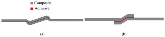
Figure 5. (a) Wavy-lap joint and (b) flat joggle flat joint (FJF).
A study from Teixeira and Sinke [71][103] showed that peel tests could be performed in bonded composite-to-metal and composite-to-composite joints using a floated rolling peel test (see Figure 6) [71][72][103,104], and concluded that using CFRP as the flexible adherend has a considerable effect on the peel load since the peel load gives a direct indication of the failure mode [71][103].