Your browser does not fully support modern features. Please upgrade for a smoother experience.
Please note this is a comparison between Version 1 by Salah Kamel and Version 2 by Rita Xu.
An induction motor is generally used in industrial applications because it is reliable, robust, and low cost. Reliability is one of the essential parameters based on which the motor is selected, and the induction motor primarily comes into force. The well-founded induction motor gives good results under various operating states. Dynamic simulation plays a significant part in evaluating the model’s design process to eliminate design errors in typical construction types and when testing the motor drive system. The induction motor is modeled in a synchronously revolving rotor flux-oriented frame, which is used as a reference.
- induction motor
- parameter estimation
- dynamic modeling
1. Introduction
The most common type of motor used in industries is the induction motor because of its reliability, robustness, and low cost. The DC motor was used initially, as it offers controlled speed and torque. However, due to the existence of a commutator, it requires constant maintenance. This problem was overcome by using an induction motor with no commutator. The elimination of the commutator in an induction motor is lower in cost and broader in its application. The main problem with an induction motor is its speed control, which is arduous. Advancements soon rectified this problem in power electronic converters. Now to control the speed of the motor, inverters were being used. Using an inverter eliminated the speed control problem, which led to another problem related to stability in an inverter-fed induction motor.
In order to carry out the analysis of an asynchronous motor, the induction motor is modeled in a frame that revolves synchronously and is flux-oriented. For sensorless vector control and the control schemes of the induction motor, excellent skills are required for at least some of the data of an asynchronous motor. So, the estimation of parameters needed to be taken care of. Due to the extensive use of induction motors across various industrial sectors, simulation and dynamic modeling of induction motors are significant to both businesses and academia. An induction motor’s dynamic and steady-state analyses are challenging. The advantage of dynamic modeling is that it aids in understanding asynchronous motor behavior in dynamic mode. The mechanical equations used in dynamic modeling include speed, torque, and time. Dynamic modeling can also be used to simulate the differential voltages, flux links, and currents between the static stator and rotating rotor. Typically, an inverter with a speed sensor drives an induction motor. However, this speed sensor has the potential to reduce system reliability and raise investment costs. Its implementation is challenging as well. Several studies use induction motors with speed sensorless drives to overcome this challenge. Different speed estimators were taken into consideration under the absence of feedback, and their performance was compared when internal parameter change and outside disturbances were present. The MRAS staging was found to be superior to the variant speed estimator. The fact that MRAS requires a detailed model of the drive system and the speed differential between the two motors, however, added to its drawback. The system cannot attain total stability if there are significant speed variances between the two motors [1][2][1,2]. In light of this, a novel sensor-free device based on an adaptive observer and a modified decoupling-controlled technology was presented. However, due to the speed estimation being unsteady in the regenerative zone, this technology was not very practical [3].
This research utilizes reduced-order observers to analyze the speed and flux assessments of asynchronous motors without sensors [4][5][6][4,5,6]. There are no gain options that do not offer stability. This researchtudy also discusses some recently discovered reduced-order observer features in addition to the aforementioned. The researcheauthors work on a technique termed vector control for two induction motors operating in parallel. This approach, which is based on system parameter averages and differences, calls for high-speed digital processors [7][8][7,8]. The analysis of a single inverted-fed multiple-asynchronous motor operating in parallel is given based on the approach of the Laplace transform of the output to the Laplace transform of the input model. It came to the conclusion that the system was unable to achieve stability under strongly loaded conditions and could only maintain stability under unequal load conditions [9][10][9,10]. The performance of high-power asynchronous motors is examined using the constant voltage by a frequency closed loop approach without sensors based on space vector pulse width modulation (SVPWM) [11][12][13][11,12,13]. It has been suggested to use a DC-to-AC converter with a DC link to drive an induction motor. The SVPWM approach aids in lowering secondary switch losses and current values. Given that the commutation circuit is active for a considerable amount of time, it is crucial to reduce losses and current values at the secondary switch [14].
The control of the switches is obtained by soft and hard switching methods with increased efficiency. Four auxiliary switches are used in order to obtain fast transients as compared to power switches. Induction motor is controlled by a quasi-resonant inverter using a direct torque control scheme with space vector modulation. The source voltage is clamped with DC link [15]. A soft switching technique is employed to manage the voltage, torque, and speed [16][17][16,17]. Induction motor monitoring is the process of identifying a motor’s developing defects. An induction motor experiences issues such as over voltage, above-rated current, high temperature, high-rated speed, monitoring of vibration, etc., while it is in operation. It is crucial to establish awareness of a motor drive system’s fault mode reaction from the perspectives of enhanced system design, sanctuary, and fault impartial control [18][19][18,19].
The evolution of induction motors from being a stable speed motor to an unpredictable speed motor and torque machine has been observed over the past few decades. However, the problem of controlling a DC motor during fault conditions [20] remained a challenge to its growth. An intrinsic and challenging topic for electrical researchers was the behavioral study of induction motors during abnormal conditions when faults are present and its diagnosis (fault diagnosis). In an industrial plant, a sudden unexpected breakdown of an induction motor due to faults can be disruptive to the high level of production process. To increase the quality and reliability and to lower the cost of production, a programmable logic controller (PLC) is being employed in many industries to carry out the automation process. PLC controlled protective relay handle failures such as phase loss, above-rated current, above-rated voltage, without unequal phase displacement of supply voltage, without unequal phase displacement of currents, and the uncontrolled repeated starting [21][22][21,22].
The rotor faults and the stator faults are the two types of faults existing in electrical motors. The most common of these faults is the stator fault. Inter-turn short circuit in one of the stator coils is the main cause ofthe origin of this type of fault. This short circuit leads to increased heating that eventually leads to ground faults and finally the breakdown of the stator takes place. Rotor faults contribute to only 20% of the overall faults in induction motors, yet fault detection diagnosis of rotor faults is important for industrial applications [23]. High current flow in adjacent bars of an induction motor happens because of broken rotor bars and air gap eccentricity. This eventually leads to further potential breakage and stator faults as well. In order to diagnose and rectify problems related to broken rotor bar and air gap eccentricity, MCSA (motor current signature analysis) is widely used in industries [24]. By applying the predicted parameters, the induction motors are designed dynamically. Thus, the working method target to develop its efficacy from the designed grip for propulsion by using a multilevel inverter in place of the existing voltage source inverter thereby diminishes the torque ripple and speed deviation under the parameter variations. The system requires better control performance, precision and quicker torque response and they were very difficult because of computing. The speed of the motors can be sensed by using the generators called Tacho-generators or encoders. This will boost up the entire expenses. Moreover, advanced technology has been developed to drive the motors without the use of speed sensors.
The parameter estimation of an induction motor by a no-load test, resistance test in DC, and a blocked rotor test is analyzed in a simulation as well as hardware setup. The dynamic modeling of an induction motor with estimated parameters is proposed in this paper. The performance investigation of induction motor drive in parallel with field-oriented control using the MRAS technique with speed controller is reviewed.
Industries frequently employ variable speed drives (VSDs) to link induction motors to the main supply. However, the use of VSDs frequently results in current ripple, making it challenging to locate the fault [25]. Discrete wavelet transform was used to obtain the various stator current harmonics. The benefit of local representation of the current signal for both healthy and malfunctioning modules is provided by DWT. Additionally, using a proportional integral (PI) controller to control KP and Ki values produces changeable data. The speed control of the induction motor is illustrated in Figure 1.To identify faults in induction motors, numerous techniques such as short-time Fourier transform, Gabor transform, wavelet transform and fast Fourier transform are used. Out of all the above-mentioned techniques, the fast Fourier transform is the easiest to implement. The only disadvantage of this technique is that transient signals using the time frequency representation cannot be analyzed by it.
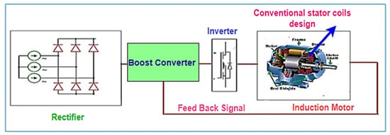
Figure 1. Controlling technique of motor drive.
On the other hand, STFT (short-time Fourier transform) is useful for analyzing short-lived signals using time frequency description, but its drawback is that it can only examine the signal with all frequencies for a stable-sized window. This marshal to imperfect frequency solution of this technique is that transient signal using the time frequency [26]. However, a powerful tool that helps in fault detection and diagnosis of motors by utilizing an adjustable-sized window is Wavelet Transform. The various software techniques and those used for fault diagnosis are Matlab, LabVIEW, Pscad, Neutral Net, etc. Artificial neural network, Fuzzy logic, and Space vector modulation are the several intelligent techniques that have been developed to detect the faults and early onset as well as avoid serious problems [27].
2. Simulation and Result Discussion of Three-Phase Induction Motor Dynamic Modeling
The value of parameters, namely, speed, d-q current, torque and three-phase voltage, is obtained from the d-q representation of AC motor, which is constructed using Simulink. The basic need of this dynamic model in state space form is that it is essential in performing the transient analysis of the induction motor or particularly for simulation study in the computer by using MATLAB/SIMULINK. The squirrel cage type of induction motor requires three inputs: the rotor speed, three-phase voltage and fundamental frequencies. When rwesearchers feed these three inputs, the outputs are the rotor speed, three-phase currents and torque [28][29][30][46,47,48]. The basic prerequisite of the d-q model is the transformation of the entire three-phase variable to the two-phase rotating frame. As a result, the AC machine design will be constituted by blocks that transform the three-phase voltage to the d-q frame and currents back to three phases. In addition, a vector of field-oriented control, which is considered considerable presentation drive control, is established on the dynamic d-q design of the induction motor. The motor can be modeled in a rotating and stationary frame. The main variables considered are the machine state space equation in the rotor frame with flux linkages illustrated in Figure 2. The simulated model is easy to develop since Simulink is a model operation programmer [31][32][33][34][49,50,51,52].
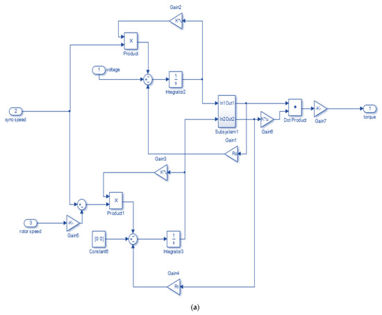

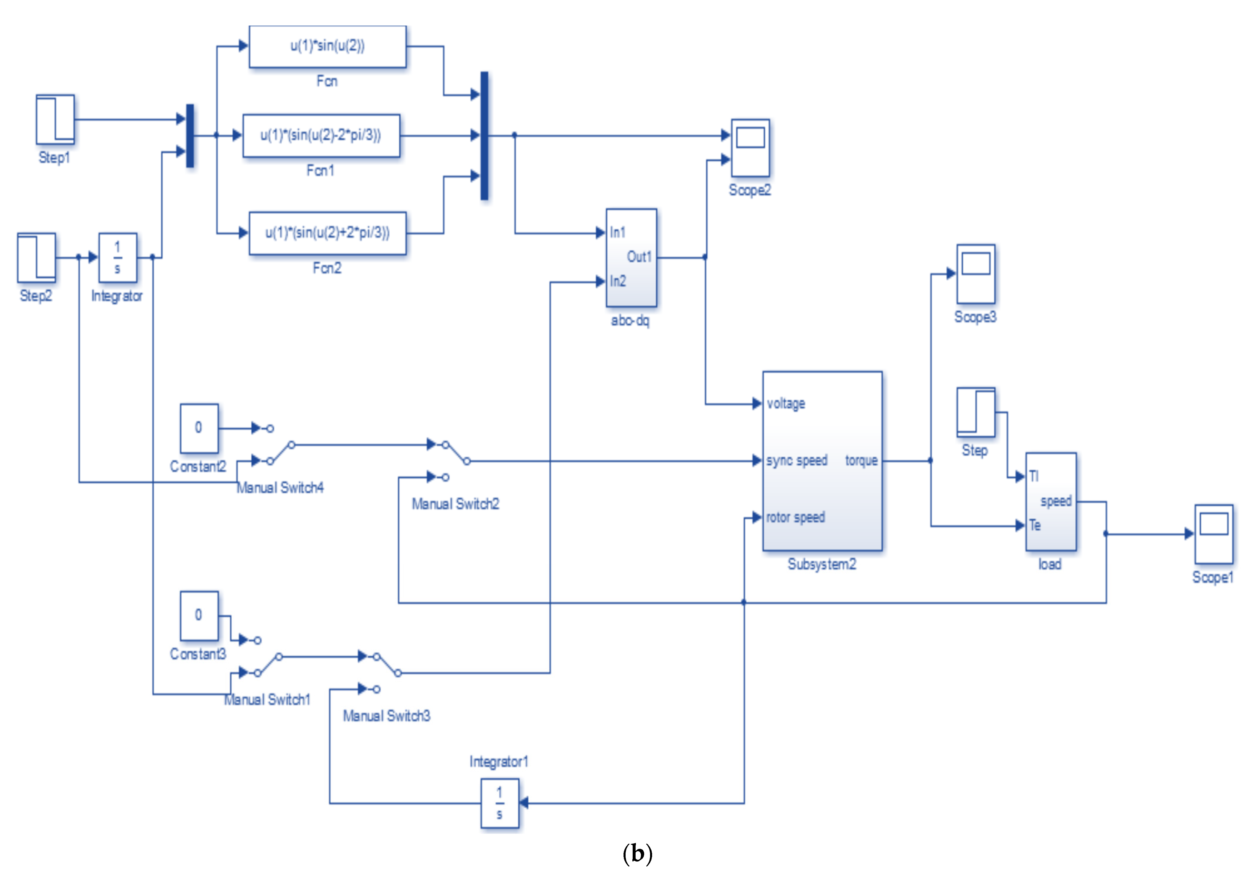
Figure 2.
(
a
) Subsystem of dynamic modeling of three-phase induction machine. (
b
) Simulation of dynamic modeling of three-phase induction machine.
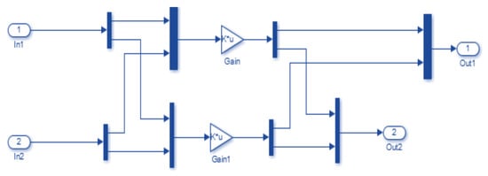
Figure 3. Flux current relation.
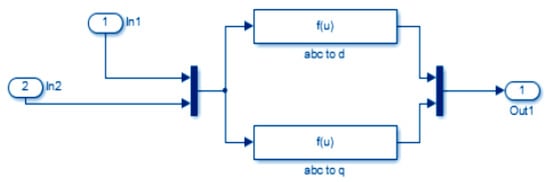
Figure 4. ABC to dq transformation.
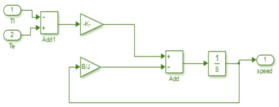
Figure 5. Load for dynamic modeling.
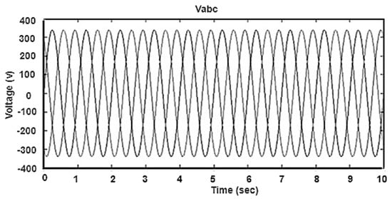
Figure 6. Output voltage of three-phase induction motor.
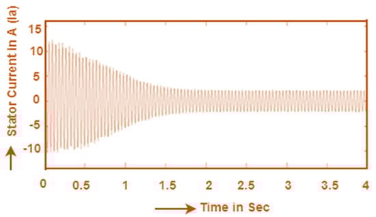
Figure 7. Stator current.
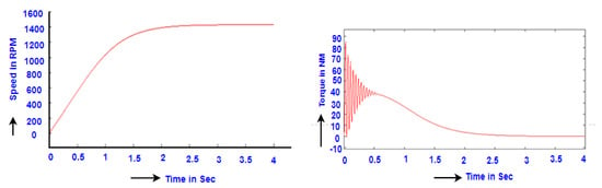
Figure 8. Speed and torque response of an induction motor.