1. Introduction
Experimentally obtained residual stress data is essential to assess mechanical performance, validate numerical models, develop new technologies and to monitor and maintain infrastructure. A significant application of railway residual stress measurements is in the manufacture of railway components
[32][1]. Residual stresses are assessed after manufacture to ensure components meet industry requirements and establish the effect of forming and thermal processes on the internal strain. Rail wheels are required to contain compressive stresses in the wheel rim to restrict crack propagation whilst rails are known to contain tensile stress in the rail head that is met with compression under wheel contact
[33][2]. Thermal processes such as welding, and laser remanufacturing have a significant effect on stress state due to heat inputs. Residual stress measurements also play a critical role in fatigue life assessment as the internal stress state evolves during in-service loading. Experimentally obtained residual stress measurements are regularly incorporated in finite element analysis (FEA) to improve simulations that optimise processes or are used for model validation to better our understanding of rail contact mechanics.
Residual stress occurs over three length scales therefore measurement techniques must have appropriate resolution for the application. Long range stresses arise from macrostrains and are classified as Type I. Type II refers to stresses that self-equilibrate over a length scale equivalent to the size of an individual grain in the microstructure. Stresses that occur within a single grain at an atomic scale are Type III stresses which may arise from dislocations or crystal lattice inhomogeneities
[34][3]. The nature and origins of residual stress is described in detail in
[35][4].
Destructive and semi-destructive techniques include strain gauge, hole drilling and the contour method which rely on machining to release elastic strain in the lattice used to calculate the corresponding stress
[36][5]. These approaches measure displacement of the cut surface or apply strain gauges to determine changes in strain which is then used to indirectly calculate stress using Hooke’s law. These methods are more accessible and easily implemented, however have limitations associated with the destruction caused by the inherent requirement for material removal, lower resolution and reduced measurement capability at increasing subsurface depths. This is shown in
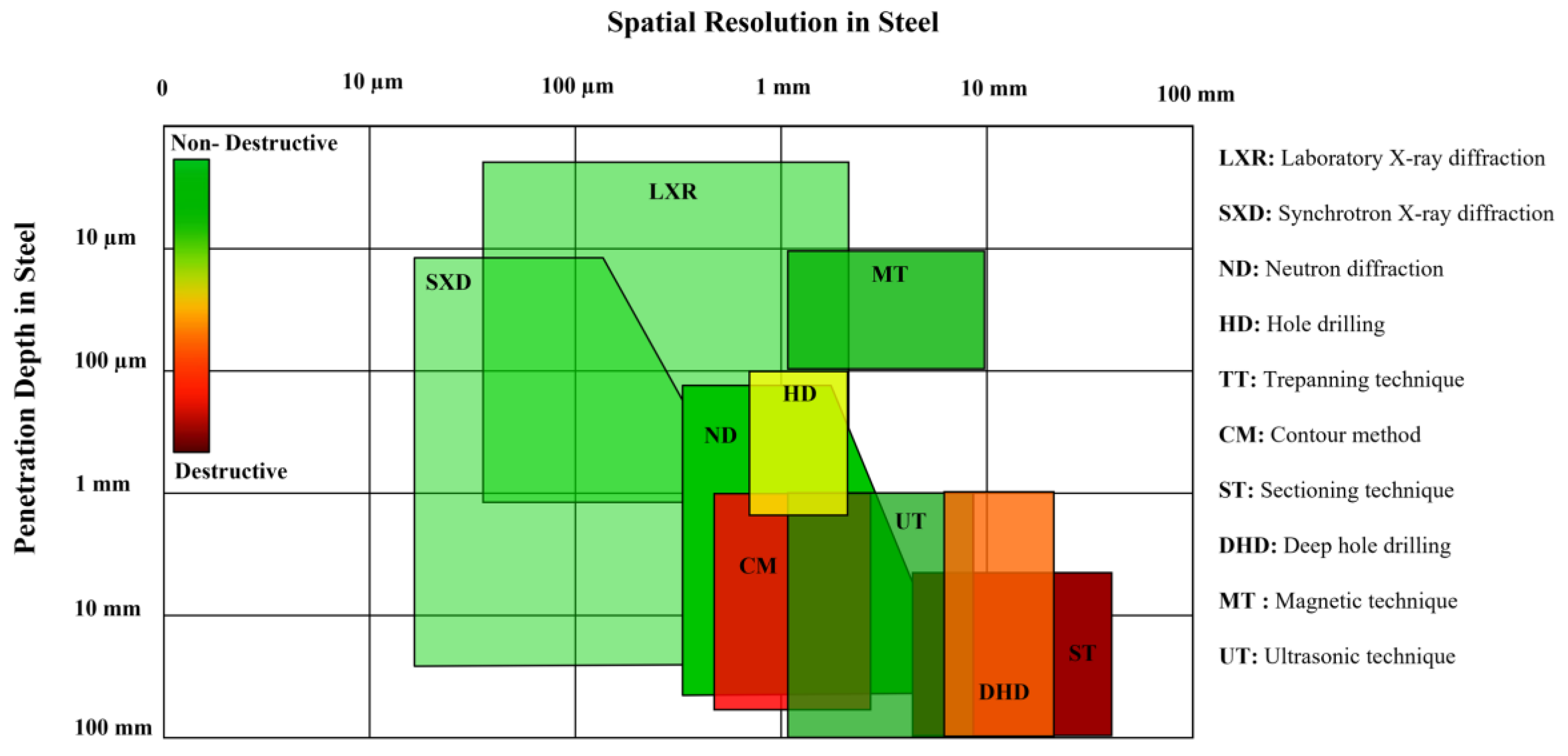
Figure 3 which presents a comparison of spatial resolution and measurement depth of destructive and non-destructive techniques for steel. Non-destructive techniques include diffraction-based methods that use neutron, X-ray and synchrotron sources as well as ultrasonic and magnetic methods. These correlate strain with the measurement of another material parameter such as lattice spacing, magnetism or movement of ultrasonic waves through the material
[37][6]. For example, internal stresses result in a shift in the diffraction pattern when compared to a strain free reference. The calculated strain caused by changes in the lattice parameter at the measurement location is then used to calculate the principal stresses. In comparison, the presence of internal stress effects how a magnetic field or ultrasonic wave passes through a material. The changes in output signal compared to a reference sample or calibration curves is then used to determine the internal stress state. Non-destructive approaches have the advantage of high accuracy and resolution and ability to perform surface and internal measurements. This is at the expense of longer data collection and processing times as well as the requirement for specialised instruments and facilities that are less accessible. A high resolution is desirable for residual stress measurements and a high spatial resolution can be achieved when the measurement depth is small, as indicated in
Figure 31. With increasing measurement depth, the attainable resolution generally decreases, even using non-destructive approaches, as the objects become larger. Therefore, it is important to choose the optimal approach for the given component with consideration of the cost, measurement time, accessibility and intended use of the output data. The method of measurement may also depend on size of component, accessibility to measurement location, required resolution and level of expertise.
Figure 31.
Spatial resolution and penetration depth of destructive and non-destructive residual stress measurement techniques for steel.
1.1. Destructive Methods
2. Destructive Methods
Destructive techniques are a well-established approach for stress evaluation and have the advantage of being highly accessible, accurate and capable of both surface and internal measurements. The mechanical method can be classified as either destructive or semi-destructive depending upon the extent of machining at the measurement site. This approach relies on evaluating the residual stresses through determining the change in strain or deformation brought about by stress relaxation after material removal. Strain relaxation is then measured with a strain gauge or using laser optics for higher resolution readings.
1.1.1. Sectioning
2.1. Sectioning
One of the earliest measurement techniques developed for residual stress analysis is Sectioning method. This approach applies electronic or mechanical strain gauges to the component surface before destructively cutting cross sections from the larger specimen. The deformation caused by a release of stress registers as a change in strain, which is measured during cutting and used to calculate the residual stress in that direction.
The sectioning technique was employed by Kang et al.
[38][7] to determine the internal stress state after manufacturing UIC 60 rails. The measurements were carried out according to the EN 13674-1 standard using 1100 mm length sections. The longitudinal and transverse stresses were measured by positioning 20 strain gauges across a 20 mm cross section as shown in
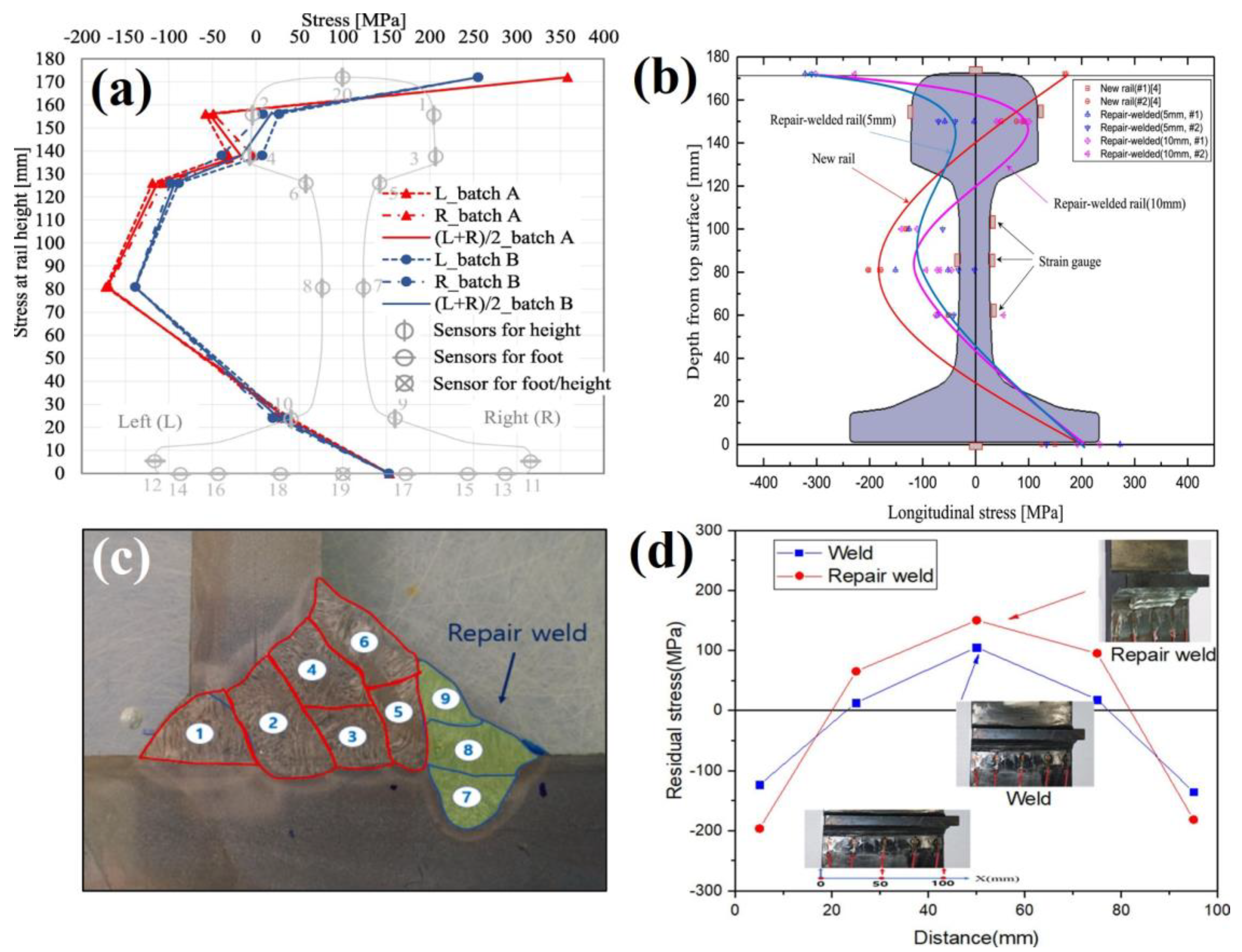
Figure 4a2. A characteristic ‘C’ shaped stress profile was obtained across the rail cross section, transitioning from tension at the surface to compression in the web before returning to tension at the foot. The transverse stress across the foot of the rail was also found to vary from 156 MPa in tension to 56 MPa compression between the centre and edge. This technique was supplemented by X-ray measurements, however due to the effects of surface roughness, the stresses obtained using sectioning showed a better agreement with literature. For this reason, the sectioning stresses were used to establish a relationship with the bending fatigue resistance. As shown in
Figure 42a the number of measurement points depends upon the number of strain gauges applied and the results may be influenced by plastic deformation during cutting or thermal inputs. A comprehensive study by Jun et al.
[39][8] measured the stress in rails repaired by arc welding using a similar sectioning approach. In comparison to the as-manufactured stresses, welding was found to induce compressive stresses in the rail head after repairs with 5 mm and 10 mm weld depths. This was determined by positioning strain gauges at eight locations at either side of the rail head, web and foot, from a section extracted from the centre of the weld site, before releasing the stress in the longitudinal, vertical and axial directions. These findings were used perform FEA that takes into consideration the solid-state phase transformation induced by welding.
The sectioning method has also proven to be a very effective approach for stress determination in large components such as railway axles. Rieger et al.
[40][9] used a strain gauge technique to measure residual stresses in wheel-set axles to ascertain the stress behaviour during crack propagation. Application of crack tip strain gauges applied to a notched sample were able to provide an approximation of stress near the crack tip which was used to understand crack growth and fatigue behaviour. A similar crack growth investigation on rail axles was also undertaken by Schindler et al.
[41][10]. Seo et al.
[42][11] used this cutting method to investigate the integrity of repair welds in a gas metal arc welded bogie frame shown
Figure 42c. Strain gauges were attached at five locations near the 60 mm long weld toe repair site. The weld repair exhibited higher compressive and tensile stresses at all measurement sites compared to an unrepaired weld as shown in
Figure 42d. These data were used to validate a FEA model using heat transfer and thermal stress analysis with consideration of the distributed heat flux and latent heat to capture the residual stresses in complex welded components. This was used to understand the influence in welding pass direction and weld repair width on the generation of internal stresses. Whilst the sectioning technique is readily implemented to inspect weld sites on larger components, this method is less suited for capturing small scale stress changes from thermal coating processes. For this reason, sectioning can be considered a lower resolution technique so is often paired with a complimentary stress measurement method.
Figure 42. (
a) Residual stress profile after sectioning a rail head Kang et al.
[38][7] (
b) Stress profile comparison of new and repair welded rails by Jun et al.
[39][8]. A study by Seo et al.
[42][11] showing a (
c) weld repair on a bogie frame and (
d) stress comparison of a repaired and unrepaired weld.
1.1.2. Hole Drilling
2.2. Hole Drilling
Hole drilling is one of the most widely implemented methods for determining residual stresses as it is a practical technique that can be performed in situ with a relatively high accuracy. This approach traditionally applies a strain gauge rosette to the workpiece to measure the equilibrium stress state before drilling a central blind hole, generally 1–5 mm in diameter
[43][12]. The relaxation and redistribution of stress is registers as changes in strain and these values are applied to elastic theory equations with the appropriate calibration constants to determine the average magnitude of the biaxial residual stress. As it is a surface measurement method, hole drilling is considered to be semi-destructive and is regularly used to determine stresses in coatings applied through direct metal deposition and spray techniques.
Ma et al.
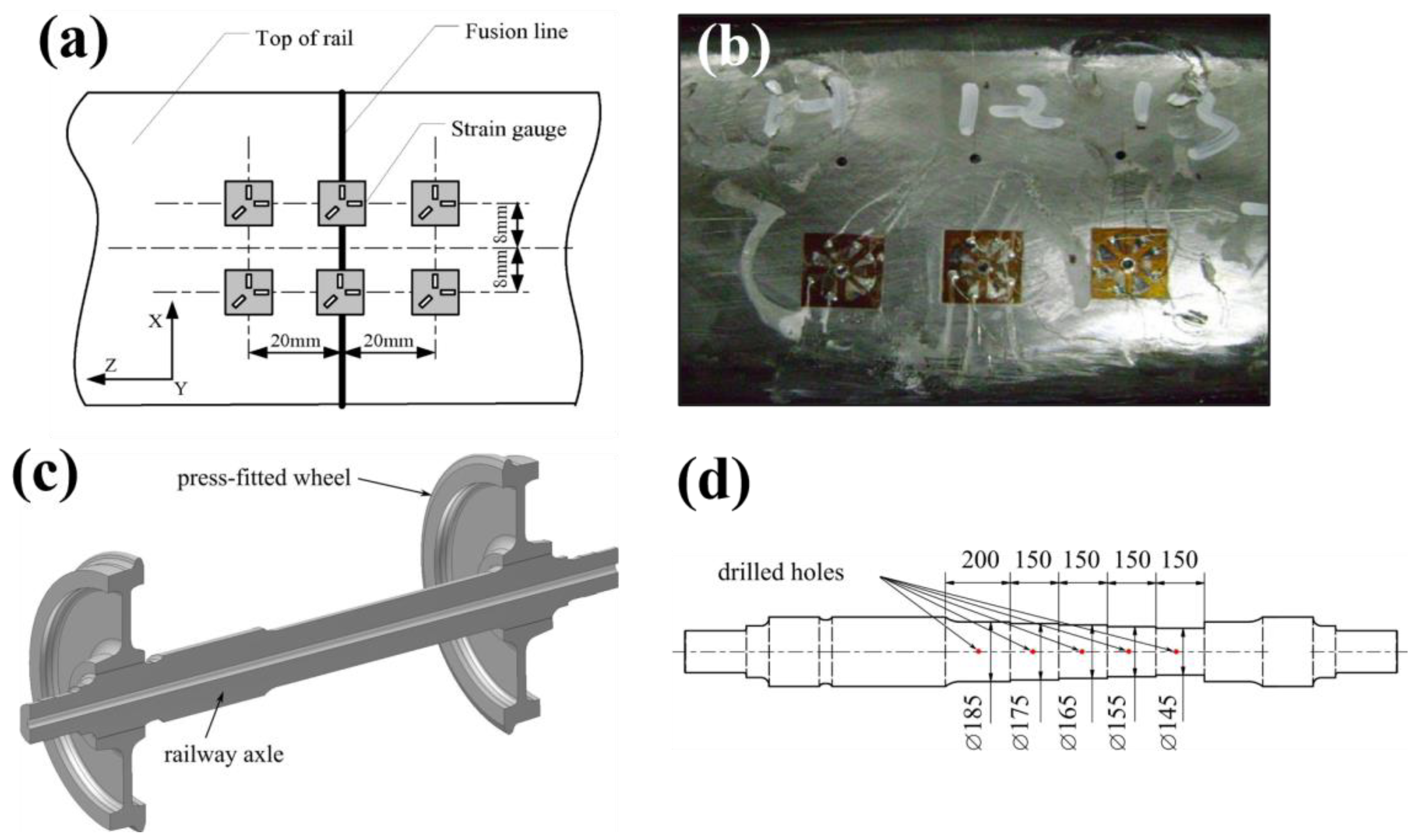
[44][13] applied hole drilling to measure the residual stress across two 1000 mm sections of U71Mn rail joined by flash-butt welding. Comprehensive measurements were taken at the fusion line and 20 mm away using six measurement locations on the rail head, three along the web and another six at the rail foot shown in
Figure 53a,b. These stress measurements were used in a 3D FE model of a quarter of the weld join in a 1000 mm rail incorporating an iterative substitute method and a material model describing solid state phase transformations. This was used to identify the critical role of phase transformations in stress generation during flash-butt welding and fatigue life assessment.
Whilst this technique was effective for surface stress measurements, it was noted that the steep stress gradient at the fusion boundary determined by FE analysis could not be captured using the hole-drilling technique due to limitations of the resolution. Zhu et al.
[45][14] implemented hole drilling techniques to investigate the influence of welding on aluminium train cars used in high-speed rail. After welding two 8 mm thick aluminium plates, hole drilling was performed at 6 locations up to 30 mm from the weld site. This showed peak stresses of 130 MPa occurring at and adjacent to the weld site and which was used to validate.
FE simulations using a double ellipsoide heat source model of welded high-speed rail components. Hole drilling was also applied to maglev welded rails by Rao et al.
[46][15] to determine the effectiveness of vibration technology for stress relief. Semi-destructive hole drilling measurements were taken at six locations along the weld site on a 3 m rail with a total drilling depth of 2 mm using a 0.2 mm/min drilling rate. Repeating stress measurements before and after vibratory stress relief on the maglev component indicated a 30% reduction in welding stress was achieved, suggesting vibration as a suitable method for stress relief when thermal processes are unsuitable.
Figure 53. A study by Ma et al.
[44][13] showing (
a) Hole drilling measurement locations around a weld and (
b) Hole drilling strain gauges applied to the rail head. A study by Pokorny et al.
[47][16] showing a (
c) schematic of railway axle and wheel configuration and (
d) measurement locations after turning to reduce axle diameter for internal measurements.
Pokorny et al.
[47][16] implemented a hole drilling approach to assess the fatigue life of heat-treated and induction hardened railway axles shown in
Figure 53c. Axial and hoop surface stresses were recorded using a 3-grid strain gauge rosette however were limited to a depth of 2.5 mm below the axle surface. To achieve deeper measurements, sections of the axle were incrementally turned to remove 5 mm from the surface and strain was remeasured using hole drilling to obtain stresses at increasing depths as shown in
Figure 53d. These measurements required post processing using FE analysis to compensate for the loss of residual stress due to the machining operations and were used to demonstrate the benefit of induction hardening in high wearing railway components.
Another approach to obtain internal stress measurements is through incremental hole drilling which takes into consideration the non-uniform distribution of stress below the surface by facilitating through thickness measurements. Strain is recorded at intermittent intervals during machining to obtain the stress at increasing depths. Whilst this method enables sub-surface measurements, the achievable depth it is generally restricted to be approximately equal to the diameter of the drilled hole
[34,48][3][17]. For example, Narayanan et al.
[49][18] used central hole drilling on determine residual stress generation in pearlitic rail laser clad with a martensitic steel. Strain gauges of 2 mm and 4 mm diameters were used to achieve measurement depths of 1 mm and 2 mm, with measurement increments of 0.05 mm and 0.1 mm, respectively. It was found that the 2 mm drill diameter used for incremental central hole drilling was more effective for surface measurements and showed strong agreement with results obtained using diffraction techniques. A deep hole drilling technique was also employed by drilling a reference hole and measuring the diameter before trepanning around this point. The change in diameter along the reference hole is then used to determine residual stress in the cladded sample. The larger drill diameters used in the deep hole drilling technique were reported to be unable to capture steep stress gradients in the cladding but were effective in determining the substrate stresses 4 mm below the cladding surface therefore is complementary to central hole drilling. From this study it was determined laser cladding of martensitic steel induces compressive stresses at the rail surface and the stress distribution stabilises during cyclic four point bending tests.
Stellite cladding on pearlitic rail was investigated by Ringsberg et al.
[50][19] using hole drilling in accordance with ASTM E837-99 on twin disc samples. A depth of 100 µm at nine measurement locations was used to determine the hoop stress of the disc samples is tensile at the cladding surface. An error margin greater than 10% resulted from the high cladding hardness influencing the drilling operation, nevertheless the results were able to validate a FEM simulation of cladding and grinding processes. Whilst hole drilling techniques can be independently implemented, there are many companies which offer residual stress measurement services. Veqter Ltd. specialises in the deep hole drilling technique for residual stress measurements in engineering components. They offer a range of residual stress measurement methods including incremental central hole drilling and the ring-core method.
The Ring-Core method develops further upon the deep hole drilling technique by use of a rosette strain gauge and machining of a larger central ring around 14–60 mm in diameter. This method allows incremental measurements up to a depth of 5 mm and is reported to have a higher sensitivity compared to other hole drilling techniques as the achievable stress relaxation is greater with a smaller diameter core, however, can lead to greater destruction of the sample. Moazam et al.
[51][20] performed a comparative study of residual stress in UIC 60 rail using the ring-core and sectioning method. Whilst both techniques identified tensile stresses in the rail foot, those obtained using the ring-core technique were 27% higher compared to those obtained using the destructive sectioning method. Despite the straightforward implementation this approach, hole drilling has reduced sensitivity at increasing depths, therefore, is most suitable for recording low level surface stresses. Further error is also introduced when the measured stress exceeds 50% of the yield stress which can facilitate local yielding and plasticity errors. The calibration coefficients can be determined both experimentally and using FE techniques as the error associated with the coefficients greatly influences the resultant stress. For higher accuracy hole drilling techniques, laser speckle interferometry or holography techniques have since been used to measure deformation with a higher degree of accuracy
[52][21].
1.2. Contour Method
3. Contour Method
The contour method was first proposed by Prime
[53][22] and is a destructive technique that uses sectioning to induce stress relaxation, producing a spatial map of the residual stress. The contour method first requires the component to be cut through a plane which relaxes the stresses normal to the surface resulting in deformation
[53,54][22][23]. Displacement data across the cut surfaces can be obtained using contact methods with coordinate measurement machines (CMM) or contactless laser surface profiling depending on the geometry and sample size. The displacement measurements are input into a stress free, elastic FE model which determines the stress required to reverse the deformation which, based on Bueckner’s principle of superposition, is the residual stress
[55][24]. This provides a 2D spatial map of the normal stress across the measured plane.
Kaiser et al.
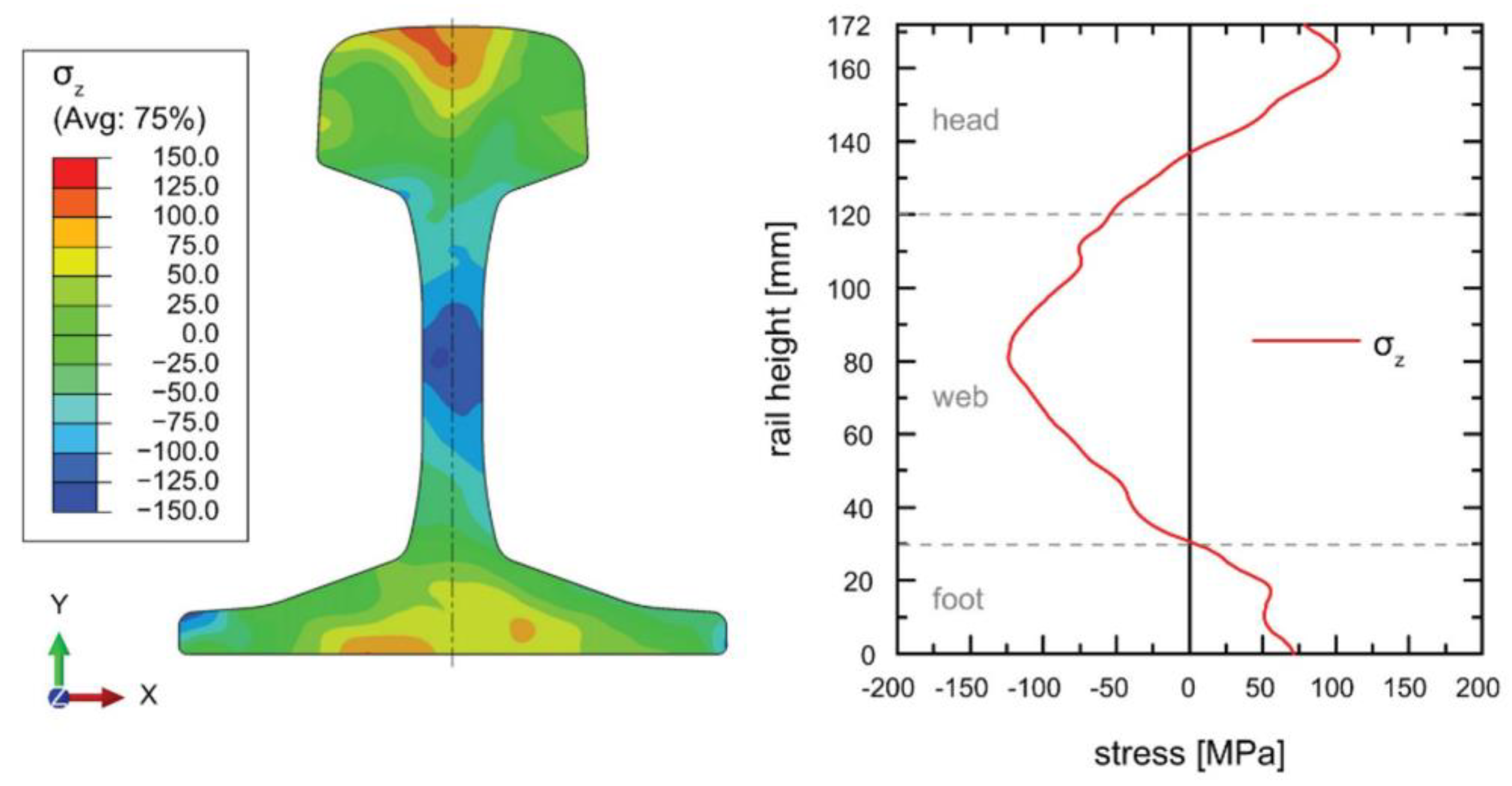
[56][25] applied the contour technique to determine the resultant stress state in a 500 mm R260 rail after roller straightening. A 1 × 1 mm
2 grid was used for stress calculation after measuring the deflected surfaces using CMM. The resultant stress map obtained using the strain contour measurements is presented in
Figure 64. The locations of tensile stress at the rail head and foot can be readily identified with a compressive region in the web. These findings were verified using diffraction measurements and FE analysis thereby validating the simulation of the rail roller straightening procedure which can be used for process optimisation. It was noted by the authors the contour measurement process to approximately twenty hours to execute in comparison to four days of measurement required by diffraction techniques. A similar study was undertaken by Banerjee et al.
[57][26] comparing the internal stress state of new rail with those exposed to varying degrees of loading and rail head or gauge corner wear.
Figure 64. A study by Kaiser et al. [56] showing a 2D stress map and profile of a rail cross section obtained using the contour method. A study by Kaiser et al. [25] showing a 2D stress map and profile of a rail cross section obtained using the contour method.
The contour method has most widely been applied for stress determination in railway rails. In these components, the longitudinal direction is the largest in dimension and contains high magnitudes of stress As the contour method is a uniaxial stress measurement technique, stresses are calculated in the direction perpendicular to the cutting plane. This makes rail particularly suited to the contour technique as the longitudinal stress can readily be measured whilst providing an overview of strain across the rail head, web and foot and is also widely applied to study welded components
[58,59][27][28]. The accuracy of the final stress measurements is dependent on the resolution and precision of the surface contour profiling which in turn is influenced by the cutting process and resultant surface roughness. Due to steps involved in measurement and post processing, accuracy of the results can vary greatly and several studies have reported different approaches to reduce error in contour calculations
[60][29]. For this reason, the contour method requires expertise to accurately implement and can be accessed through professional stress testing services. For example, The StressMap group in the United Kingdom are leading specialists in the contour method and offer stress measuring services using a range of standard techniques whilst SONATS is an industrial testing firm based in France who offers contour and residual stress measurements to a worldwide customer base.