Your browser does not fully support modern features. Please upgrade for a smoother experience.
Please note this is a comparison between Version 2 by Peter Tang and Version 1 by WAN SHARUZI WAN HARUN.
Additive manufacturing (AM) highlights developing complex and efficient parts for various uses. Fused deposition modelling (FDM) is the most frequent fabrication procedure used to make polymer products. Although it is widely used, due to its low characteristics, such as weak mechanical properties and poor surface, the types of polymer material that may be produced are limited, affecting the structural applications of FDM. Therefore, the FDM process utilises the polymer composition to produce a better physical product.
- FDM
- polymer
- composite
- properties
- process parameter
- application
1. Introduction
Manufacturing industries are rapidly evolving in terms of the technology and materials involved. AM has transformed the industries of affordable three-dimensional (3D) solid structure fabrication and rapidly converting computer-generated designs into actual parts [1,2][1][2]. In recent years, AM has emerged as one of the most effective processes where the material is printed layer-upon-layer for building 3D products. Rapid prototyping, rapid manufacturing, and 3D printing are terms used to describe AM, which is snowballing in the manufacturing sector because the product can be served directly to the consumers, resulting in lower capital expenditure and transportation costs. Furthermore, AM fabricates customised parts in small quantities, which do not need special tools and allow the fabrication of complex geometries and assemblies [3,4][3][4]. In addition, 3D printing technology has advanced rapidly in recent years, and now various field applications are available, such as industries in the biomedical [5,6][5][6], aerospace [7[7][8],8], and automotive fields [9]. Unlike the traditional manufacturing processes [10], 3D printing is an AM method that works by stacking material from one layer over another to produce complex structures [11].
Metals, polymers, and composites can be used in AM. Many applications use AM technologies to create a complex shape [12]. There are many AM processes, such as selective laser sintering (SLS) [13], fused deposition modelling (FDM) [14], direct metal deposition (DMD) [15], laminated object manufacturing (LOM) [16], ink jet modelling (IJM) [17], and stereo-lithography (SLA) [18]. These procedures differ in printing material, process parameters, precision level, and end-use application [19]. FDM, also known as fused filament fabrication (FFF), is very well used in 3D printing. Stratasys Inc. in the United States invented the method during the 1990s. Printing factors such as printing orientation, air gap, layer thickness, raster width, and raster angle can be adjusted to improve the quality of printed parts [20]. Although FDM is known for its low operating cost and low investment cost, the printed products are more fragile as compared to other standard plastic manufacturing methods, such as moulding, injection [21], CNC [22], and extrusion [23,24][23][24].
Composites are materials of two or more physically or chemically separate phases divided by a discrete interface. The different elements are deliberately merged to produce a system with much more effective structural and functional properties than any of the constituents could achieve on their own [25].
Whether natural or synthetic, polymer composites are amongst the most significant applications of polymer. In various polymer matrices, the polymer composite is a multiphase solid substance in which one phase has at least 1, 2, or 3 dimensions. The polymer composites are viable for use as a high-performance composite when the reinforcing properties differ significantly from or exceed that matrix. The polymer matrix composite is the most enhanced composite material; these composite materials have various classifications of fibres such as natural and synthetic fibres as the reinforced materials in various types of polymer, for instance, thermoplastic polymer or thermoset polymer, which can be moulded into various shapes and sizes to produce various types of antiquated material [26].
By applying the feeding force created by the grooved bearing and driving gear, material in the form of a filament is fed into the liquefier head over the spool, as shown in Figure 1. The thermoplastic filament is heated to a glass transition temperature before being deposited in layers using a heated nozzle. The head of the liquefier travels through the X-Y plane according to the tool path supplied by programming. Support material can be eliminated with a solvent after fabrication [27].
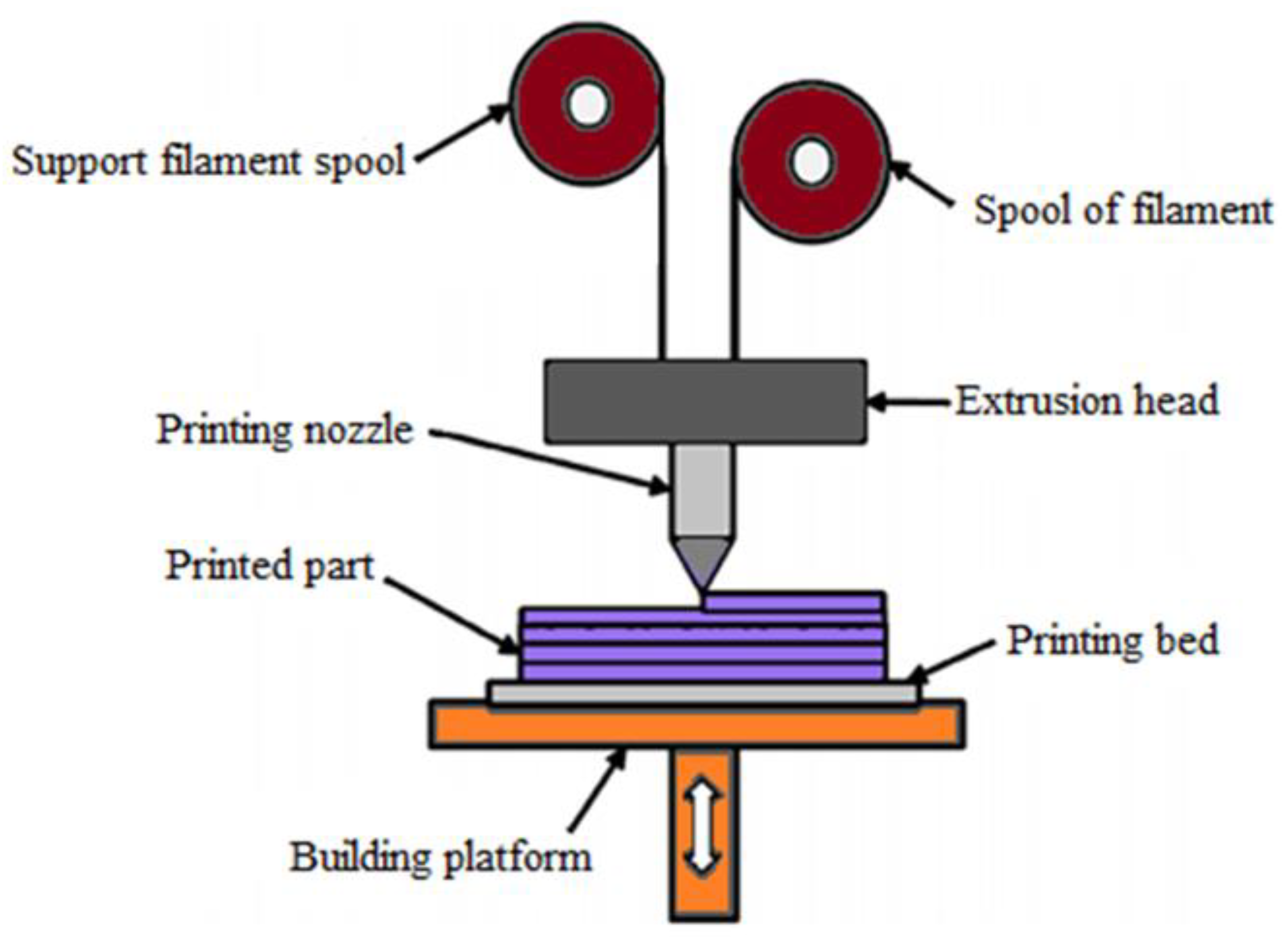
Figure 1.
Schematic diagram of FDM process.
Figure 2 shows the steps involved in the FDM process. The process begins with designing a digital model of a part by using CAD software. Then, 3D scanning, and reverse engineering are also performed to create a digital model. Later, the digital model is converted into a Standard Tessellation Language or Standard Triangle Language (STL) file. The STL file contains data about the surface geometry of the model. Then, the STL file is fed into the slicer software after conversion. Slicing determines the condition of printed pieces. Next, they apply information from the STL file, and the slicer generates G-codes. The generated G-code is the same as the CNC machine. It also controls the extruder and platform’s direction during printing. After converting the G-codes from an STL file, the 3D printer is ready to print a physical object of the design. This printing differs regardless of the kind of AM technique used. In the FDM process, the nozzle follows the G-code instructions and moves to deposit the melted filament in layers.
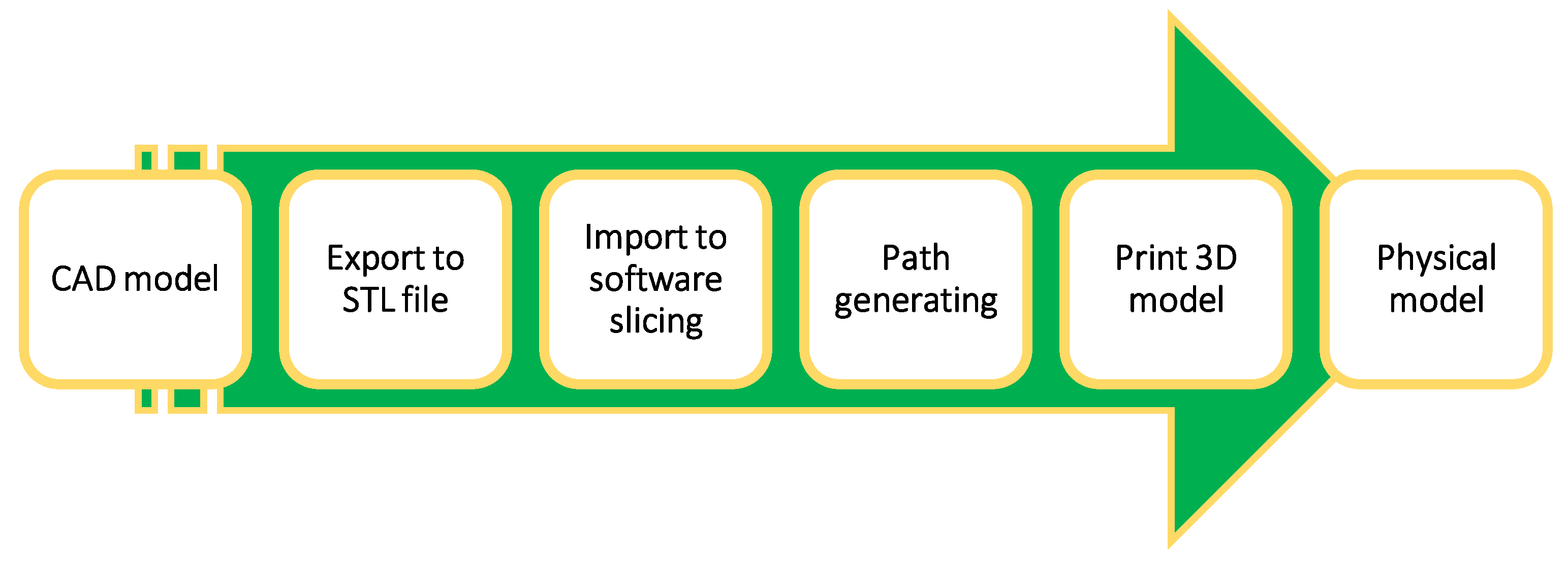
Figure 2.
Steps involved in the FDM process to produce 3D printed parts.
2. Composite Materials
Composite materials have developed into engineering materials that are remarkable and diverse because they are strong in domain areas that do not deform easily and have a high strength-to-weight ratio [30,31][28][29]. A composite material is defined by its name, which implies that it is made of different materials. Compositional engineering occurs when many constituent materials with significantly different chemical or/and physical properties are combined to form a new material with unique characteristics that are not present in the individual element [32,33,34,35,36,37][30][31][32][33][34][35]. Compared to the qualities of individual materials, this augmentation makes composite materials preferable. There are different types of composite material: scale base composite, reinforced base composite, matrix material base composite, and bio-composite. Figure 3 summarises the types of composite material. A composite material comprises two materials, namely base and filler. Because it wraps and bonds the reinforcement of other materials, the base material is commonly known as a matrix or a binder material. Fibres, particles, fragments, and natural or synthetic whiskers are filler materials [38,39,40][36][37][38]. Matrix is a soft phase with mechanical and physical properties, such as formability, ductility, and thermal conductivity. Material with high stiffness, strength, and low thermal fluctuation is included in the matrix reinforcement. The reinforcement phase of composites is always stiffer and more robust than the matrix because it conveys the load applied to the material.
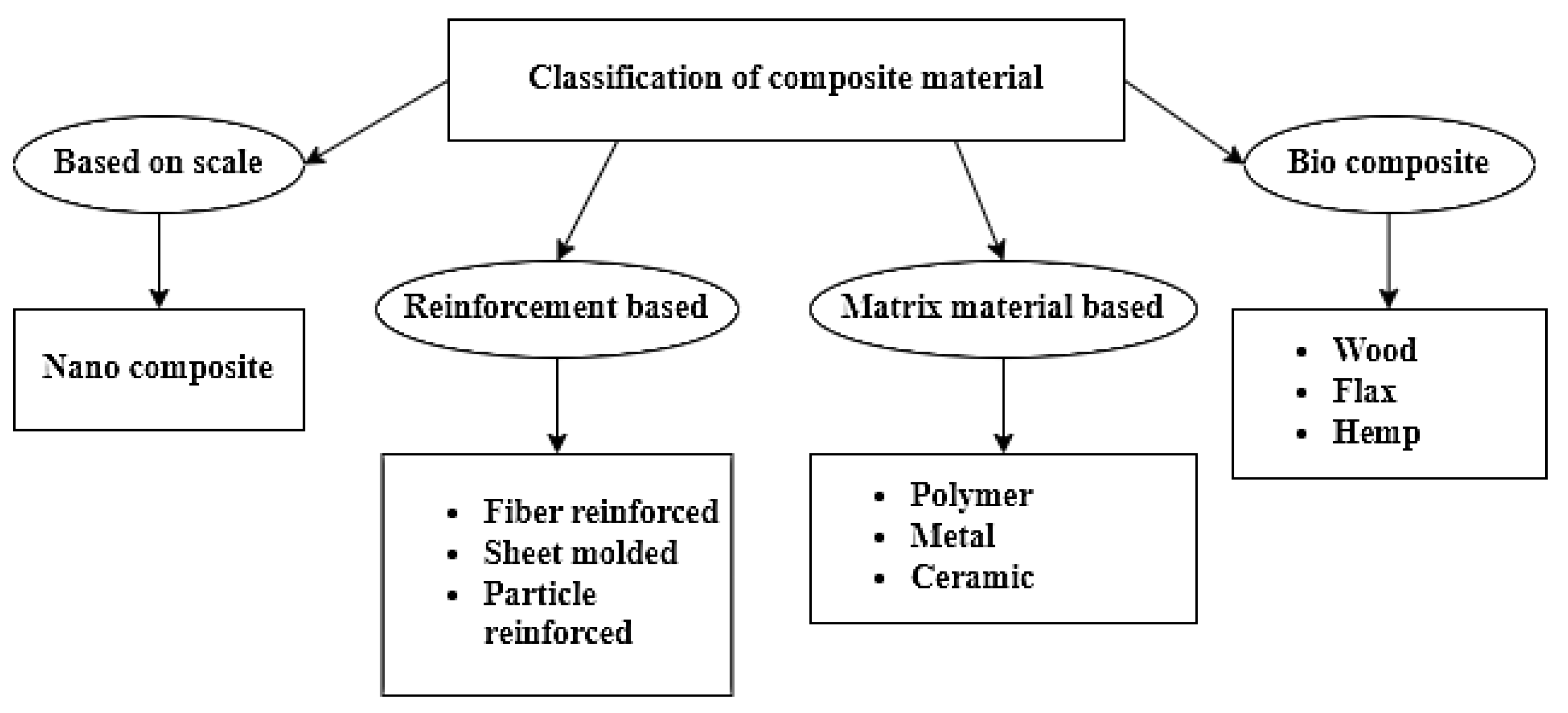
Figure 3.
Detailed classification of composite materials.
3. Processing Parameter of FDM
The process parameters influence the material’s accuracy, efficiency, and characteristics. As a result, a fundamental study into numerous process factors must be included to produce functionally efficient parts by utilising the FDM technology. Therefore, the FDM printing process specifies and briefly describes several parameters.
3.1. Layer Height
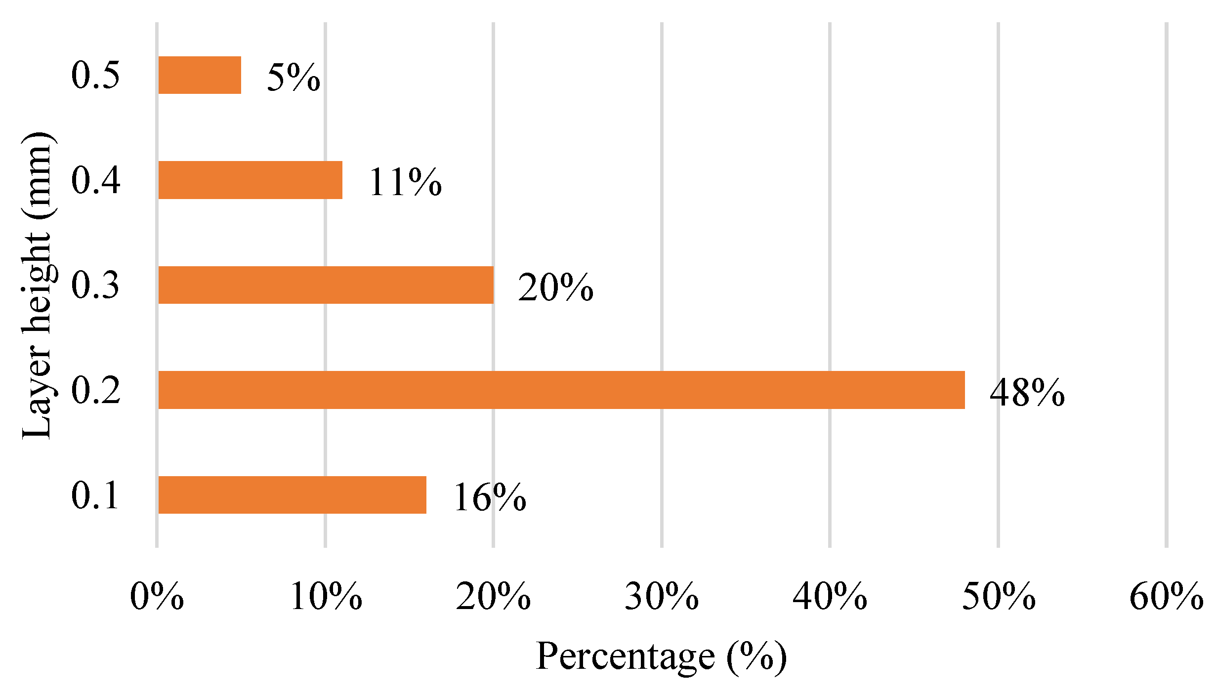
Figure 4 shows the bar chart for layer height used in the FDM process 3D printer. Nearly half of the 100% for layer height is 0.2 mm, consisting of 48%. Most FDM printers only have a size up to a 0.4 mm printing nozzle. The least-used layer height is 0.5 mm. The layer height is also defined as layer thickness. It means the thickness of material extruded from the printing nozzle for printing the physical part. The layer height can be adjusted to the printed parts’ referenced thickness. It represents the number of layers formed in a single pass all along the vertical axis of the FDM machine. Material deposition heights will be smaller than the nozzle diameter of the extruder.
Figure 4.
Layer heights used in FDM machine during printing process.
The value is solely dependent on the diameter of the extruder tip. Layer height has an unavoidable impact on the impact and bending properties of the fabricated product. A minimum layer thickness is recommended to obtain better bending properties, and to increase layer thickness as it improves impact properties [139,140][39][40]. Compared to other parameters such as shell thickness and part orientation, the impact of layer thickness, as discussed in the literature, contributes roughly 85% of FDM-produced parts’ accuracy [141][41]. Based on the ANOVA results, other studies also show its significance (12.23% contribution) following the raster width parameter. The part dimension and layer thickness are determined to have a direct correlation. This indicates that thicker layers yield larger pieces, resulting in more significant dimensional variances [142][42].
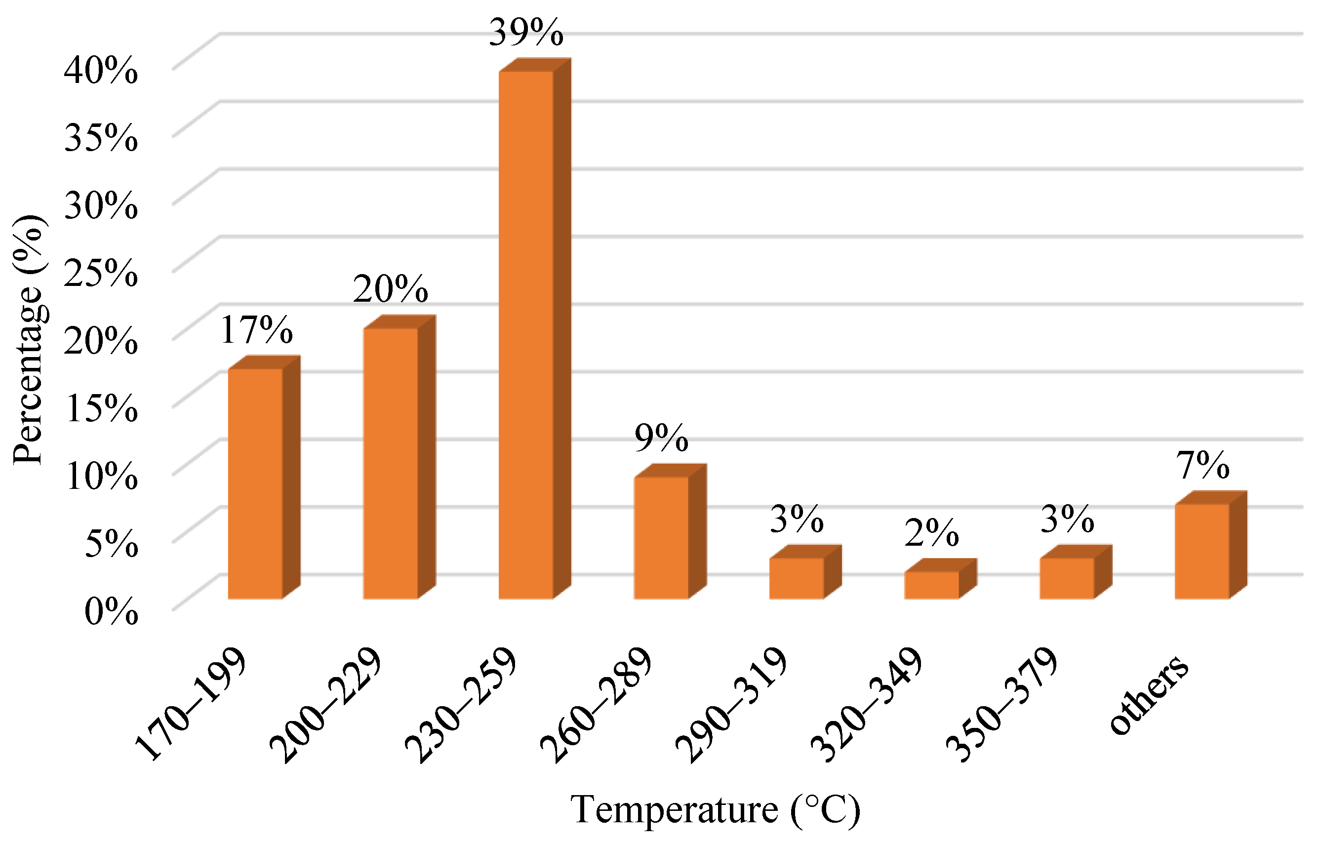
3.2. Nozzle Temperature
Extrusion temperature is the temperature controlled inside the heating nozzle of FDM even before the material is extruded [143][43]. It changes the viscosity of printing material, affecting the part’s properties. The ideal temperature must be maintained since it can impact the viscosity of the filament material, which affects the printed part. Figure 5 shows the various nozzle temperatures used for the FDM process. The highest temperature used is from 230 °C to 259 °C. The second-highest range is 200 °C to 229 °C. Others stand for ranges from 380 °C to 409 °C, 410 °C to 439 °C, and 440 °C to 469 °C. As the material is extruded from the nozzle, the internal tension develops as the temperature of the material cools from the initial temperature to the temperature of the chamber. This occurs as a result of variations in deposition speed. The internal stress can cause interlayer and intralayer deformation, leading to manufactured part failure [144][44]. The nozzle temperature melts the filament into a semi-liquid state to print the physical parts. The extrusion temperature would be an essential parameter because if the temperature were low, the material would have a high viscosity which would be hard to extrude. However, if it is too high, the substance will flow, and dripping might occur. As a result, it is vital to fix the extrusion temperature to the correct value, depending on the material used for printing [141][41].
Figure 5.
Range of nozzle temperature for various material via FDM process.
3.3. Bed Temperature
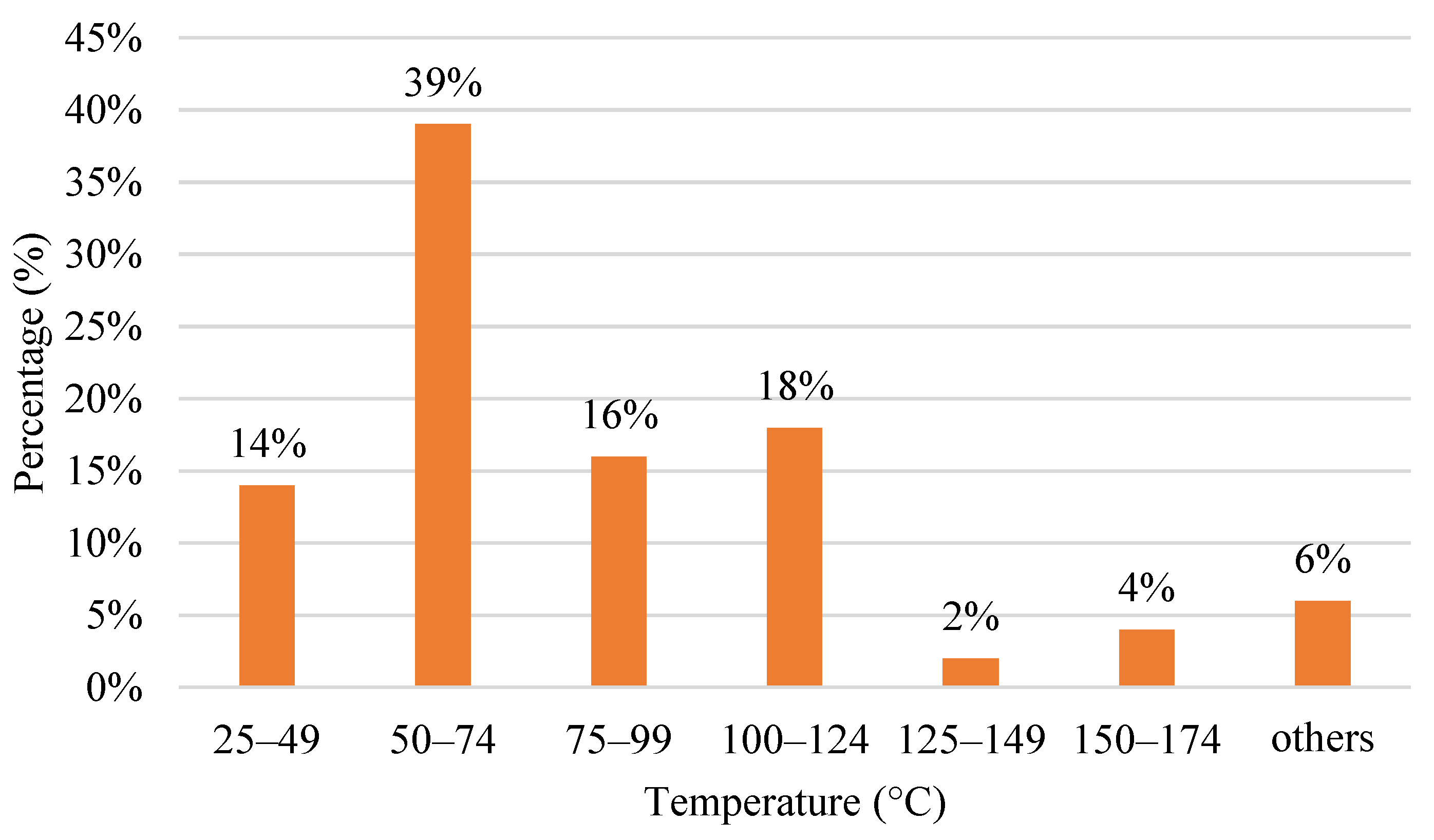
Besides nozzle temperature, bed temperature also plays a vital role in printing. Bed temperature, commonly known as heat bed, is a platform whereby the part is printed during printing. Bed temperature has two primary purposes. Firstly, it can prevent the printing object from warping. Warping is a familiar problem when the edges of the printed material are cooled at various rates compared to the rest of the material. When a heated and stretched material is extruded onto the cold and contracted material, it causes tensions in the material after the new layer cools. This causes the cooled plastic to warp upwards and changes the appearance of the print. Secondly, it helps in layer adhesion. It increases the surface energy of the print bed to improve the bonding strength of the first layer. The prints will not adhere properly to the build plate if the first layer adhesion is poor, which increases the possibility of a print failure. When it has good adhesion, it helps to reduce the warping of the printing material. Besides preventing warping and layer adhesion, the bed temperature also retains the temperature of the printing platform. The bed temperature also eases the removal process of printed parts. The removal process is straightforward with the bed temperature by using any cutting tools or forces. Figure 6 shows a column chart for the bed temperature of the FDM process. The highest range used is from 50 °C to 70 °C with 39%. The second primarily used range lies from 100 °C to 124 °C, with 18%. The minor range used is 125 °C to 149 °C. Others are ranged from 175 °C to 199 °C and from 200 °C to 224 °C.
Figure 6.
The range for bed temperature used in the FDM process for various material.
3.4. Printing Speed
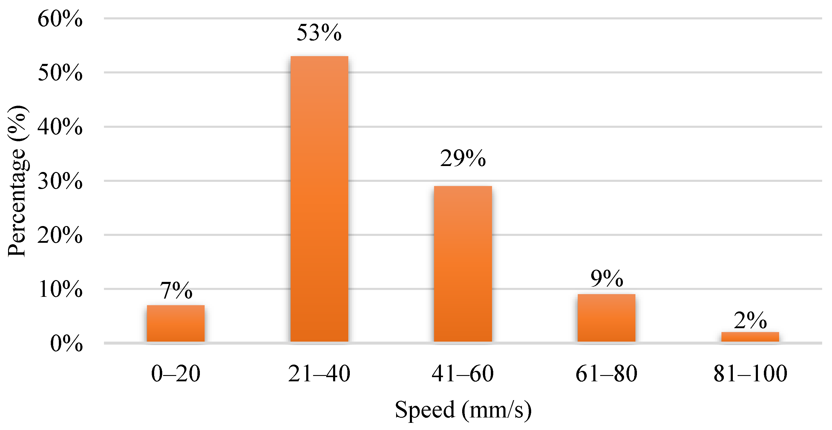
In 3D printing technology, print speed is the most critical setting. As the name implies, print speed determines how fast the motors of the printer move. The electric motors controlling the X- and Y-axes and the extruder are included in the printing speed. The speed of the nozzle represents the deposition of filaments over a region of the built component during deposition. Printing speed is equal to the amount of time taken to print. It has a significant influence on the quality of the fabricated model. However, in narrower layer printing, the impact of the printing speed is negligible [145][45]. Figure 7 shows the printing speed used in the FDM process. The frequently used printing speed is around 21 mm/s to 40 mm/s. The next is 41 mm/s to 60 mm/s.
Figure 7.
Range of printing speed used in FDM process.
3.5. Building Orientation
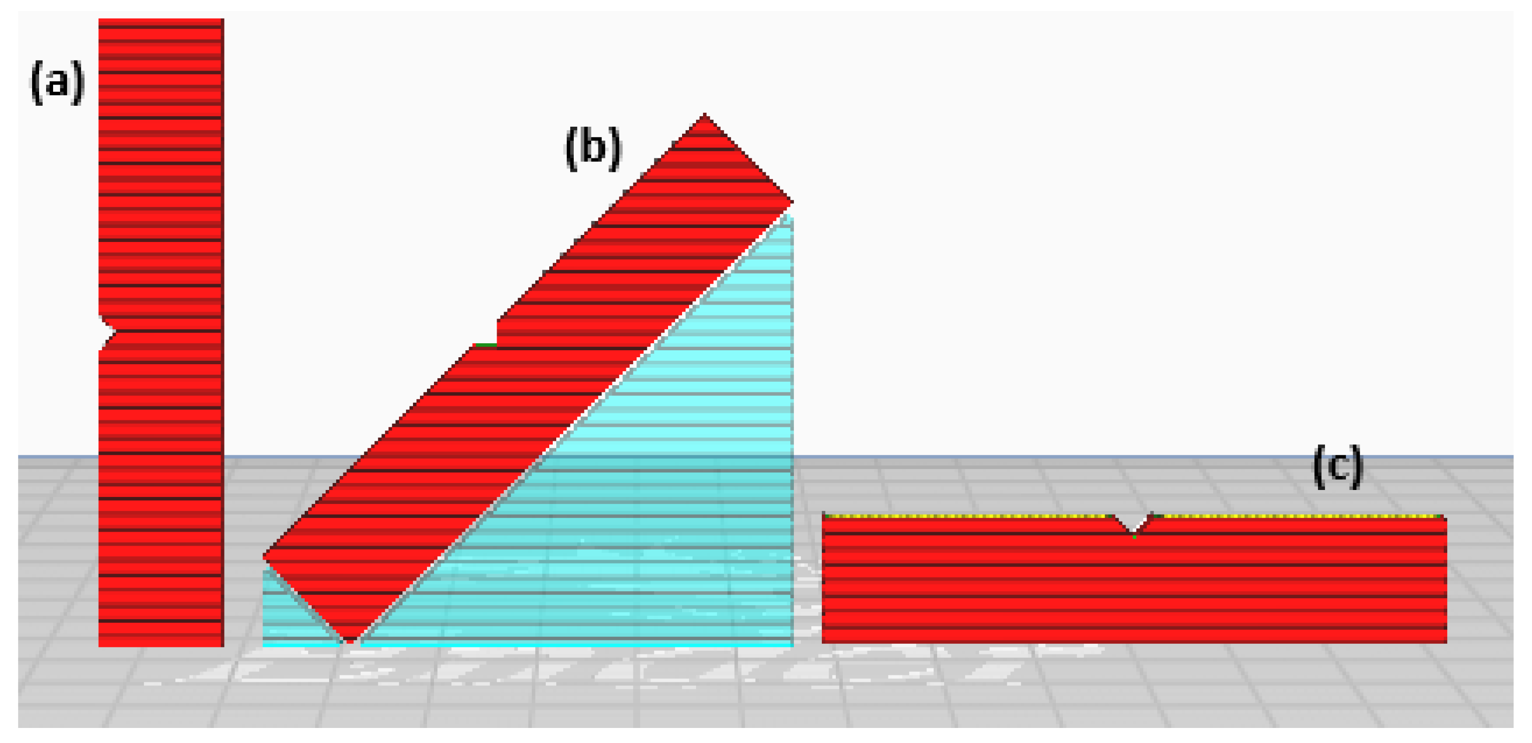
Building orientation is also known as building direction. Besides the layer resolution, the build orientation is also very crucial to the process. The building orientation is the angle at which the part is placed about the horizontal axis of the build platform. Surface roughness and staircase effect are determined by resolution, whereas print quality and layer arrangement are determined by build orientation, and fusion is proportional to the mechanical properties of the printed object [14,146][14][46]. It describes how parts are positioned on the build platform about the three primary axes of the machine tool, which are the X-axis, Y-axis, and Z-axis [147][47]. Figure 8 shows the printing orientation of the impact test sample for 0°, 45°, and 90°. Afrose [148][48] observed that specimens’ best strain energy storage capacity and fatigue life are printed at a 45-degree angle.
Figure 8.
Impact samples printed with various (
a
) 90°, (
b
) 45°, and (
c
) 0° building orientations.
3.6. Screw Type
3.6.1. Single Screw Extruder
The single screw extruder was invented in the 1870s. It is the most extensively used extruder due to its ease of operation in polymer and rubber production [149][49]. The most basic single screw extruder configuration is a single revolving screw positioned inside a static cylindrical barrel split into three distinct zones: the compression zone, feed zone, and metering zone [150][50]. Different pressures can be generated along the length of the screw by varying the depth and pitch of the screw flight within every zone. The screw flight pitch and depth are generally chosen at bigger scales than from other zones to achieve low pressure at the feed zone, which consistently feeds material from the hopper into the extruder barrel [151][51]. Solid materials must be melted and homogenised as part of the rotating conveyance into the compression zone to form a suitable shape for distribution in the metering zone. As a result, the decreasing screw flight and pitch depth cause a progressive increase in barrel pressure along the length of the compression zone [152][52]. For less demanding applications, kneading, devolatilising, and mixing can be conducted in this processing zone [152,153][52][53]. A homogenous product by consistent structure can be achieved from die extrusion by stabilising the effervescent flow to a steady condition in the last metering zone. Fabricating extrusion-based goods using a single screw extruder is particularly well suited for high viscosity polymers since it may produce high pressure during operation [154][54].
The material is fed into the barrel through the feed throat by gravity force, and in most single screw extruders, the speed of the screw controls the output rate. High pressure to transfer material from the feed system causes the plastic pellet or powder to condense into a solid bed [155][55]. Periodically, the mass flow rate is unaffected by the speed of the screw and is regulated directly from the feed system by using a starving fed mechanism, resulting in an output rate that is lower than the forwarding efficiency of the screw [156,157][56][57]. The single screw extruder has only one screw and is used to make homogeneous polymers in a continuous shape [149,158][49][58]. Single screw extruders are unsuitable for heat-sensitive polymers due to higher friction and thermal energy as the screw speed increases.
Furthermore, significant pressure is used during the extrusion process, compressing the ingredients to generate filaments. However, it may lead to agglomeration and poor mixing due to a lack of shear deformation. [159,160,161][59][60][61].
3.6.2. Twin Screw Extruder
Although the single screw extruder process seems simple and inexpensive, it lacks the mixing capacity required to produce a polymer composite using many compounded components. As a result, in the late 1930s, a modified extruder known as a twin screw extruder that contained two screws placed next to each other at a modular barrel was developed to form intimate blends of two or more different materials [162][62]. Unlike a single screw extruder, a twin screw extruder provides a more vital shear force amongst the screws and barrel and the rotating screws, resulting in the proper mixing of materials [163][63]. As a result, a broad range of mixing operations and heat transfers are achieved with a faster throughput, independent of the screw’s speed. On the other hand, the counter-rotating system can generate a sizeable extensional shear force between the gaps between the two screws, allowing for a significant potential air entrapment, pressure generation, and extended retention period while using the minimal speed and output of the screw [164,165][64][65]. Both can be divided into two categories: entirely intermeshing and non-intermeshing. Because of its self-wiping function, the intermeshing twin screw extruder may not only eliminate non-motion throughout the extrusion, but also avoid excessive overheating of raw materials. After the process, the rotation of the screws removes residual material from the screw roots and cleans the entire inside barrel.
Meanwhile, this popular layout can help reduce product waste at the end of the manufacturing process [166][66]. The mutually different screws positioned in the extruder barrel for the non-intermeshing type result in low torque generation and weak interaction, making it a better choice for processing high viscosity materials and venting to eliminate interior volatile substances [167][67].
4. Properties of FDM-Polymer Composite
4.1. Mechanical Analysis
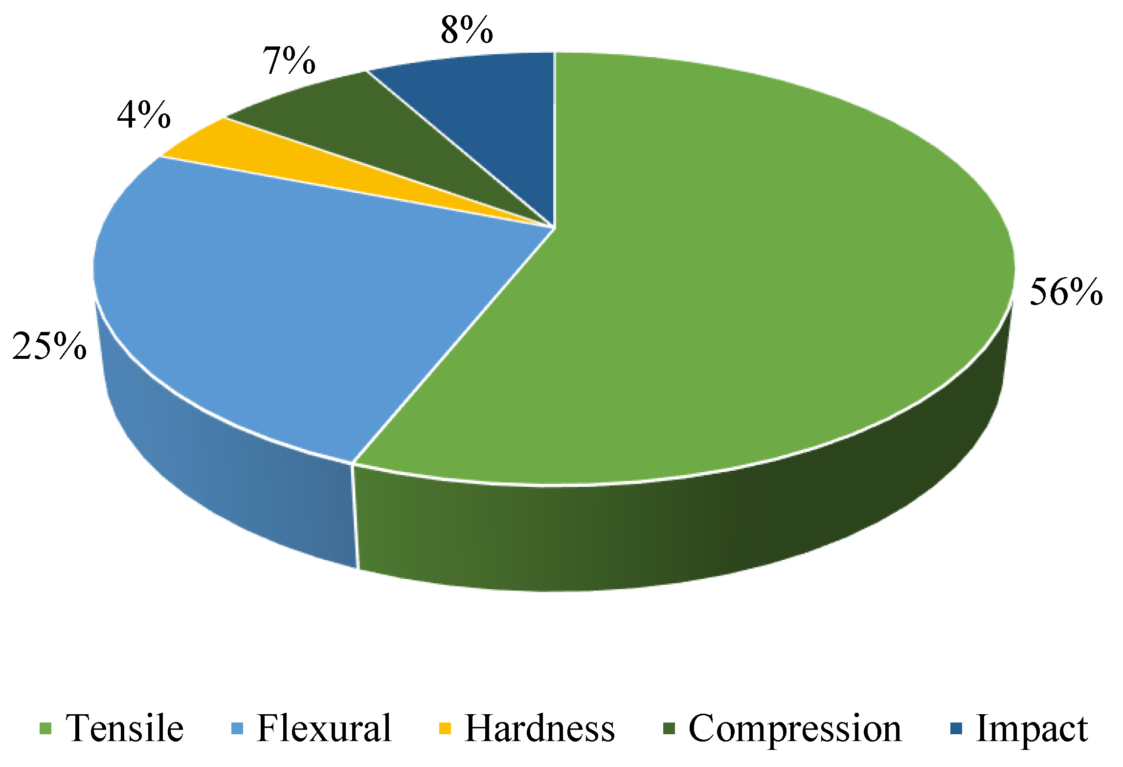
Mechanical properties are testing aids in evaluating and designing materials and products, allowing them to last longer and be more efficient and cheaper. AM polymers’ characteristics are tested using ASTM and ISO test methods. They also aid in the creation of desired items. In order to prepare the sample and conduct mechanical experiments, research organisations use ASTM standard criteria; for example, practically all research groups evaluated for tensile tests [176,177][68][69] employ ASTM D638. The majority of research findings state that the component’s ultimate tensile strength, yield strength, elasticity, and elongation are mostly affected by the process parameters. Figure 9 shows the mechanical properties that were tested from 2011 to 2021. From the study conducted, the most tested mechanical property is tensile. Flexural is the second most thoroughly tested mechanical property. Fatigue behaviour is one of the mechanical properties that has undergone minor testing. The tensile test is used on samples to determine material parameters, such as ultimate tensile strength, yield stress, Young’s modulus, ductility, and toughness. There are many shapes and designs to choose from when producing a sample for the tensile test. Even though there are various options for the test sample design, it must adhere to ASTM standards [178][70].
Figure 9.
Mechanical properties that were studied primarily in the FDM process from the year 2011 to 2021.
4.2. Thermal Analysis
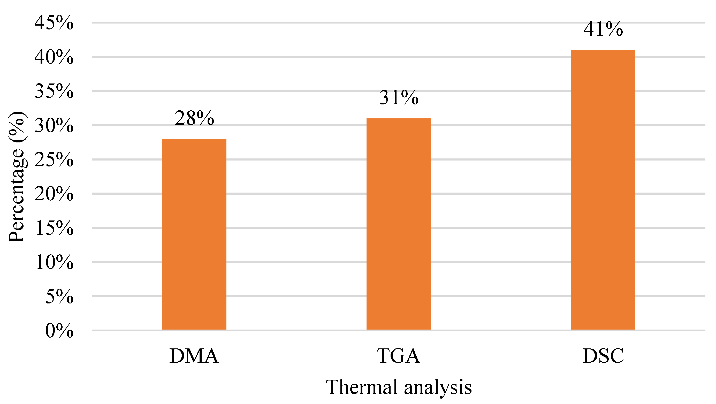
Figure 10 shows a chart of thermal analyses. There are three types of thermal analyses: dynamic mechanical analysis (DMA), thermogravimetric analysis (TGA), and differential scanning calorimetry (DSC). The highest thermal analysis used is DSC with 41%, while TGA is 31%. Essential qualities of energetic materials are their thermal properties, which are strongly related to safety during manufacturing, storage, transportation, and usage. The thermal properties of energetic materials can be determined quickly, efficiently, and effectively using thermal analysis tools [184][71]. However, in thermal analysis investigations, the fluctuation of thermogravimetry (TGA) curves frequently occurs for unknown reasons, and the mass–loss curves, for example, grow or drop drastically and even surpass the complete scales of instruments. Furthermore, the differential scanning calorimetry/differential thermal analysis (DSC/DTA) is inconsistent with TG because the crucible frequently shifts or slips off the sample pan [185][72].
Figure 10.
Thermal analysis of FDM polymer composite from the year 2011 to 2021.
5. Application of Polymer Composite in 3D Printing
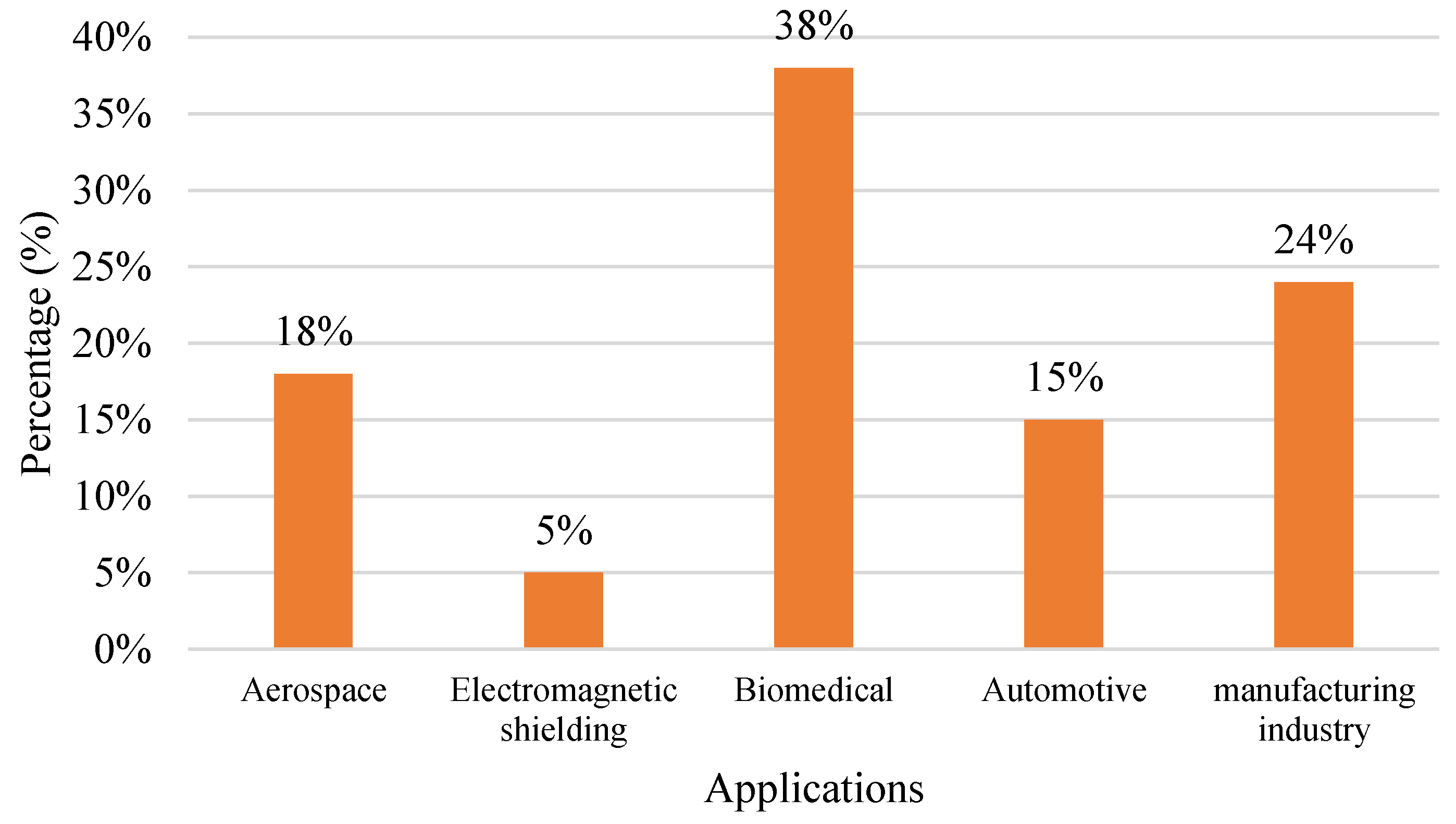
Various industries are using the FDM process to produce products. Figure 11 shows the FDM application in industries. The biomedical field is one industry that utilises the FDM process for its product, whereby the industry utilises 38% out of 100%. Manufacturing is the second-highest industry in utilising the FDM process, and aerospace is the third-highest industry. In recent times, the use of FDM technology has grown in popularity, particularly in aerospace, medical, and automobile fields. In addition, the overall quality of prototypes printed for the aerospace sector is in high demand since they are utilised to examine the fluid dynamic behaviour of models [141][41].
Figure 11.
Application of FDM using polymer composite.
References
- Hart, K.R.; Wetzel, E.D. Fracture behavior of additively manufactured acrylonitrile butadiene styrene (ABS) materials. Eng. Fract. Mech. 2017, 177, 1–13.
- Almuallim, B.; Harun, W.S.W.; Rikabi, I.J.R.; Mohammed, H.A. Thermally conductive polymer nanocomposites for filament-based additive manufacturing. J. Mater. Sci. 2022, 57, 3993–4019.
- Patil, P.; Singh, D.; Raykar, S.J.; Bhamu, J. Multi-objective optimization of process parameters of Fused Deposition Modeling (FDM) for printing Polylactic Acid (PLA) polymer components. Mater. Today Proc. 2021, 45, 4880–4885.
- Harun, W.S.W.; Kamariah, M.S.I.N.; Muhamad, N.; Ghani, S.A.C.; Ahmad, F.; Mohamed, Z. A review of powder additive manufacturing processes for metallic biomaterials. Powder Technol. 2018, 327, 128–151.
- Kumar, R.; Kumar, M.; Chohan, J.S. The role of additive manufacturing for biomedical applications: A critical review. J. Manuf. Processes 2021, 64, 828–850.
- Talib, S.; Gupta, S.; Chaudhary, V.; Gupta, P.; Wahid, M.A. Additive manufacturing: Materials, techniques and biomedical applications. Mater. Today Proc. 2021, 46, 6847–6851.
- Blakey-Milner, B.; Gradl, P.; Snedden, G.; Brooks, M.; Pitot, J.; Lopez, E.; Leary, M.; Berto, F.; Plessis, A. Metal additive manufacturing in aerospace: A review. Mater. Des. 2021, 209, 110008.
- Najmon, J.C.; Raeisi, S.; Tovar, A. Review of additive manufacturing technologies and applications in the aerospace industry. In Additive Manufacturing for the Aerospace Industry; Froes, F., Boyer, R., Eds.; Elsevier: Amsterdam, The Netherlands, 2019; pp. 7–31.
- Sargini, M.I.M.; Masood, S.H.; Palanisamy, S.; Jayamani, E.; Kapoor, A. Additive manufacturing of an automotive brake pedal by metal fused deposition modelling. Mater. Today Proc. 2021, 45, 4601–4605.
- Jimeno-Morenilla, A.; Azariadis, P.; Molina-Carmona, R.; Kyratzi, S.; Moulianitis, V. Technology enablers for the implementation of Industry 4.0 to traditional manufacturing sectors: A review. Comput. Ind. 2021, 125, 103390.
- Jayaraghul, T.K.; Karthik, K.; Yaswanth, A.; Venkatesan, M. Nozzle flow characteristics of P.E.E.K (Poly-ether ether ketone) material used in 3D-printing. Mater. Today Proc. 2021, 44, 2963–2967.
- Deomore, S.A.; Raykar, S.J. Multi-criteria decision making paradigm for selection of best printing parameters of fused deposition modeling. Mater. Today Proc. 2021, 44, 2562–2565.
- Stoia, D.I.; Marsavina, L. Effect of Aluminum Particles on the Fracture Toughness of Polyamide-based Parts Obtained by Selective Laser Sintering (SLS). Procedia Struct. Integr. 2019, 18, 163–169.
- Khan, S.; Joshi, K.; Deshmukh, S. A comprehensive review on effect of printing parameters on mechanical properties of FDM printed parts. Mater. Today Proc. 2021, 50, 2119–2127.
- Ahmed, N. Direct metal fabrication in rapid prototyping: A review. J. Manuf. Process. 2019, 42, 167–191.
- Ahn, D.; Kweon, J.; Choi, J.; Lee, S. Quantification of surface roughness of parts processed by laminated object manufacturing. J. Mater. Process. Technol. 2012, 212, 339–346.
- Derby, B. Additive Manufacture of Ceramics Components by Inkjet Printing. Engineering 2015, 1, 113–123.
- Revilla-León, M.; Methani, M.M.; Morton, D.; Zandinejad, A. Internal and marginal discrepancies associated with stereolithography (SLA) additively manufactured zirconia crowns. J. Prosthet. Dent. 2020, 124, 730–737.
- Giri, J.; Shahane, P.; Jachak, S.; Chadge, R.; Giri, P. Optimization of FDM process parameters for dual extruder 3d printer using Artificial Neural network. Mater. Today Proc. 2021, 43, 3242–3249.
- Angelopoulos, P.M.; Samouhos, M.; Taxiarchou, M. Functional fillers in composite filaments for fused filament fabrication; a review. Mater. Today Proc. 2021, 37, 4031–4043.
- Dehghan-Manshadi, A.; Yu, P.; Dargusch, M.; StJohn, D.; Qian, M. Metal injection moulding of surgical tools, biomaterials and medical devices: A review. Powder Technol. 2020, 364, 189–204.
- Maurya, R.K.; Niranjan, M.S. An experimental analysis of process parameters for EN-36C alloy steel using CNC lathe—A review. Mater. Today Proc. 2020, 25, 773–777.
- Doungkom, P.; Jiamjiroch, K. Analysis of Printing Pattern and Infiltration Percent over the Tensile Properties of PLA Printed Parts by a Fuse Deposition Modelling Printer. IOP Conf. Ser. Mater. Sci. Eng. 2019, 501, 012028.
- Wickramasinghe, S.; Do, T.; Tran, P. FDM-based 3D printing of polymer and associated composite: A review on mechanical properties, defects and treatments. Polymers 2020, 12, 1529.
- Thomas, S.; Joseph, K.; Malhotra, S.K.; Goda, K.; Sreekala, M.S. Polymer composites. In Macro- and Microcomposites; John Wiley & Sons: Hoboken, NJ, USA, 2012; Volume 1.
- Asim, M.; Saba, N.; Jawaid, M.; Nasir, M. Potential of natural fiber/biomass filler-reinforced polymer composites in aerospace applications. In Sustainable Composites for Aerospace Applications; Jawaid, M., Thariq, M., Eds.; Woodhead Publishing: Sawston, UK, 2018; pp. 253–268.
- Gavali, V.C.; Kubade, P.R.; Kulkarni, H.B. Property Enhancement of Carbon Fiber Reinforced Polymer Composites Prepared by Fused Deposition Modeling. Mater. Today Proc. 2020, 23, 221–229.
- Singh, A.P.; Sharma, M.; Singh, I. A review of modeling and control during drilling of fiber reinforced plastic composites. Compos. Part B Eng. 2013, 47, 118–125.
- Dandekar, C.R.; Shin, Y.C. Modeling of machining of composite materials: A review. Int. J. Mach. Tools Manuf. 2012, 57, 102–121.
- Koli, D.K.; Agnihotri, G.; Purohit, R. Properties and characterization of Al-Al2O3 composites processed by casting and powder metallurgy routes. Int. J. Latest Trends Eng. Technol. (IJLTET) 2013, 2, 486–496.
- Clyne, T.W.; Hull, D. An Introduction to Composite Materials, 3rd ed.; Cambridge University Press: Cambridge, UK, 2019.
- Gibson, R.F. A review of recent research on mechanics of multifunctional composite materials and structures. Compos. Struct. 2010, 92, 2793–2810.
- Mittal, V.; Saini, R.; Sinha, S. Natural fiber-mediated epoxy composites—A review. Compos. Part B Eng. 2016, 99, 425–435.
- Qin, Q.; Ye, J. Toughening Mechanisms in Composite Materials; Elsevier: Amsterdam, The Netherlands, 2015.
- Cen, H.; Kang, Y.; Lei, Z.; Qin, Q.; Qiu, W. Micromechanics analysis of Kevlar-29 aramid fiber and epoxy resin microdroplet composite by Micro-Raman spectroscopy. Compos. Struct. 2006, 75, 532–538.
- Qin, Q.H. Introduction to the composite and its toughening mechanisms. In Toughening Mechanisms in Composite Materials; Woodhead Publishing Series in Composites Science and Engineering; Woodhead Publishing: Sawston, UK, 2015; pp. 1–32.
- Tsai, S.W.; Hahn, H.T. Introduction to Composite Materials; Routledge: Boca Raton, FL, USA, 2018.
- Barbero, E.J. Introduction to Composite Materials Design; CRC press: Boca Raton, FL, USA, 2010.
- de Toro, E.V.; Sobrino, J.C.; Martinez, A.M.; Eguia, V.M. Analysis of the influence of the variables of the Fused Deposition Modeling (FDM) process on the mechanical properties of a carbon fiber-reinforced polyamide. Procedia Manuf. 2019, 41, 731–738.
- Barrios, J.M.; Romero, P.E. Improvement of Surface Roughness and Hydrophobicity in PETG Parts Manufactured via Fused Deposition Modeling (FDM): An Application in 3D Printed Self–Cleaning Parts. Materials 2019, 12, 2499.
- Zharylkassyn, B.; Perveen, A.; Talamona, D. Effect of process parameters and materials on the dimensional accuracy of FDM parts. Mater. Today Proc. 2020, 44, 1307–1311.
- Nancharaiah, T.; Raju, D.R.; Raju, V.R. An experimental investigation on surface quality and dimensional accuracy of FDM components. Int. J. Emerg. Technol. 2010, 1, 106–111.
- Dey, A.; Yodo, N. A Systematic Survey of FDM Process Parameter Optimization and Their Influence on Part Characteristics. J. Manuf. Mater. Process. 2019, 3, 64.
- Wang, T.M.; Xi, J.T.; Jin, Y. A model research for prototype warp deformation in the FDM process. Int. J. Adv. Manuf. Technol. 2007, 33, 1087–1096.
- van Manen, T.; Janbaz, S.; Zadpoor, A.A. Programming the shape-shifting of flat soft matter. Mater. Today 2018, 21, 144–163.
- Redwood, B.; Schöffer, F.; Garret, B. The 3D Printing Handbook: Technologies, Design and Applications; 3D Hubs: Amsterdam, The Netherlands, 2017.
- Kaur, G.; Singari, R.M.; Kumar, H. A review of fused filament fabrication (FFF): Process parameters and their impact on the tribological behavior of polymers (ABS). Mater. Today Proc. 2021, 51, 854–860.
- Afrose, M.F.; Masood, S.H.; Ioveniti, P.; Nikzad, M.; Sbarski, I. Effects of part build orientations on fatigue behaviour of FDM-processed PLA material. Prog. Addit. Manuf. 2016, 1, 21–28.
- Patil, H.; Tiwari, R.V.; Repka, M.A. Hot-melt extrusion: From theory to application in pharmaceutical formulation. AAPS PharmSciTech 2016, 17, 20–42.
- Gaspar-Cunha, A.; Covas, J.A.; Costa, M.; Fernanda, P.; Costa, L. Optimization of Single Screw Extrusion; Technicka Univerzita Kosice: Košice, Slovakia, 2018.
- Maniruzzaman, M.; Boateng, J.S.; Snowden, M.J.; Douroumis, D. A review of hot-melt extrusion: Process technology to pharmaceutical products. Int. Sch. Res. Not. 2012, 2012, 436763.
- Singhal, S.; Lohar, V.K.; Arora, V. Hot Melt Extrusion Technique. Webmedcentral Pharm. Sci. 2011, 2, 1.
- Chokshi, R.; Zia, H. Hot-melt extrusion technique: A review. Iran. J. Pharm. Res. 2004, 3, 3–16.
- Censi, R.; Gigliobianco, M.R.; Casadidio, C. Hot Melt Extrusion: Highlighting Physicochemical Factors to Be Investigated While Designing and Optimizing a Hot Melt Extrusion Process. Pharmaceutics 2018, 10, 89.
- Abeykoon, C. Polymer Extrusion: A Study on Thermal Monitoring Techniques and Melting Issues, 1st ed.; LAP LAMBERT Academic Publishing: Berlin, Germany, 2012.
- Wilczyński, K.J.; Lewandowski, A.; Nastaj, A.; Wilczyriski, K. Modeling for Starve Fed/Flood Fed Mixing Single-Screw Extruders. Int. Polym. Process. 2016, 31, 82–91.
- Repka, M.A.; Langley, N.; DiNunzio, J. Melt Extrusion: Materials, Technology and Drug Product Design; Springer Science & Business Media: New York, NY, USA, 2013; Volume 9.
- Geus, H.G. Developments in manufacturing techniques for technical nonwovens. In Advances in Technical Nonwovens; Woodhead Publishing: Sawston, UK, 2016; pp. 133–153.
- Wilczyński, K.; Nastaj, A.; Wilczyński, K.J. Melting Model for Starve Fed Single Screw Extrusion of Thermoplastics. Int. Polym. Process. 2013, 28, 34–42.
- Wilczyński, K.; Lewandowski, A.; Wilczyński, K.J. Experimental study for starve-fed single screw extrusion of thermoplastics. Polym. Eng. Sci. 2012, 52, 1258–1270.
- Tan, D.K.; Maniruzzaman, M.; Nokhodchi, A. Advanced Pharmaceutical Applications of Hot-Melt Extrusion Coupled with Fused Deposition Modelling (FDM) 3D Printing for Personalised Drug Delivery. Pharmaceutics 2018, 10, 203.
- Wilczynski, K.; White, J.L. Melting Model for Intermeshing Counter-Rotating Twin-Screw Extruders. Polym. Eng. Sci. 2003, 43, 1715–1726.
- Bouvier, J.M.; Campanella, O.H. Extrusion Processing Technology: Food and Non-Food Biomaterials; John Wiley & Sons: Hoboken, NJ, USA, 2014.
- Tadmor, Z.; Gogos, C.G. Principles of Polymer Processing; John Wiley & Sons: Hoboken, NJ, USA, 2013.
- Crowley, M.M.; Zhang, F.; Repka, M.A.; Thumma, S.; Upadhye, S.B.; Battu, S.K.; McGinity, J.W.; Martin, C. Pharmaceutical Applications of Hot-Melt Extrusion: Part I. Drug Dev. Ind. Pharm. 2007, 33, 909–926.
- Wilczyński, K.; Lewandowski, A.; Wilczynski, K.J. Experimental study of melting of LDPE/PS polyblend in an intermeshing counter-rotating twin screw extruder. Polym. Eng. Sci. 2012, 52, 449–458.
- Wilson, M.; Williams, M.A.; Jones, D.S.; Andrews, G.P. Hot-melt extrusion technology and pharmaceutical application. Ther. Deliv. 2012, 3, 787–797.
- Ahn, S.H.; Montero, M.; Odell, D.; Roundy, S.; Wright, P.K. Anisotropic material properties of fused deposition modeling ABS. Rapid Prototyp. J. 2002, 8, 4.
- Nabipour, M.; Akhoundi, B.; Saed, A.B. Manufacturing of polymer/metal composites by fused deposition modeling process with polyethylene. J. Appl. Polym. Sci. 2020, 137, 48717.
- Mogan, J.; Sandanamsamy, L.; Halim, N.A.; Kadirgama, K.; Ramasamy, D. A review of FDM and graphene-based polymer composite. IOP Conf. Ser. Mater. Sci. Eng. 2021, 1078, 012032.
- Liu, Z. Review and Prospect of Thermal Analysis Technology Applied to Study Thermal Properties of Energetic Materials. FirePhysChem 2021, 1, 129–138.
- Qian, H.; Kai, W.; Hongde, X.; Li, Z.; Penghui, Y. Investigation on foaming and secondary reactions with a novel visual equipment and impacts on thermal analysis. Thermochim. Acta 2021, 703, 179014.
More