2. Manufacturing Methods of Archimedes Screw Turbines
This section discusses the methods used to manufacture Archimedes screw turbines. It compiles different manufacturing methods taken from various research works and documented patents. Based on these documents on AST research, it was identified that there were four major classifications of manufacturing methods used to produce ASTs, such as traditional manufacturing, CNC manufacturing, molding manufacturing, and 3D printing. Furthermore, current works on ASTs scarcely describe the manufacturing process of the AST prototypes used in their experiments.
2.1. Traditional Manufacturing
Traditional manufacturing refers to metal-based fabrication methods to manufacture ASTs using conventional metalworking processes that have been used in the industry. This manufacturing method is mostly a type of subtractive manufacturing, which involves staged and gradual removal of material, commonly metal, from the workpiece. Unlike the straightforward flow of 3D-printing-based manufacturing, traditional manufacturing comprises multifarious processes, and several combinations of these processes can be employed to realize the final product. Research works that mentioned the use of traditional manufacturing on their AST prototypes are discussed in the following.
Rohmer et al.
[22][39] conducted an experimental and numerical study on a manufactured AST to investigate its performance. In their study, they described the novelty of their manufacturing method. They stressed the adverse effects of welding in AST, stating that welding must be of high quality and have no defect to prevent changes in material properties that would induce corrosion in the AST. The welding process was removed from the manufacturing process by making their prototype modular to improve durability and economic life, leaving only the milling and cutting processes. Their AST design comprised a tubular core and screw blades; at least one blade was around the tubular core, and the rest were removable. The modularity of their design allowed the AST to have modifiable geometric parameters post manufacture.
Erinofiardi et al.
[23][26] experimentally studied a manufactured AST to investigate the turbine’s rotational speed and power relationship. They only mentioned that the AST was manufactured using simple manufacturing methods. A Polyvinyl chloride (PVC) pipe was used for the ducting of the turbine, while the screw blades were made of aluminum, and the screw blades were fastened to the turbine shaft using rivets; the material for the turbine shaft was not disclosed.
Abdullah et al.
[24][40] conducted a numerical and experimental study on a manufactured AST to investigate the effect of flow rate, shaft inclination angle, and the number of screw blades on AST performance. They mentioned that their prototype was made from locally available materials, consisting of 12 screw blades welded onto a hollow turbine shaft. The screw blades were made from annular metal sheets, and these sheets were shaped into helixes using an undescribed process. The screw blades and turbine shaft were made of stainless steel, and the ducting was a galvanized iron tube with one lateral side being cut.
Durrani et al.
[25][41] proposed the use of an AST to utilize sewage water for hydropower generation. They mentioned that the manufacturing process they used for their prototype included cutting, rolling, and welding. Galvanized metal sheets were used for ducting and the screw blades, while the material for the turbine shaft was unspecified.
Syam et al.
[26][42] experimentally tested their manufactured AST to gauge its performance based on flow rate, torque, power, and efficiency. They showed that their prototype comprised a hollow tube shaft to which the screw blades were attached, but it was not specified if the connection was welded or fastened. It was only mentioned that the turbine utilized was made from 201 stainless steel.
Bauyon
[27][57] designed and manufactured an AST for application in a river stream in the Philippines. They showed several processes in the manufacturing of their prototype. A vise bench was used to reshape metal sheets into screw blades, and the screw blades were fastened onto a hollow PVC pipe used as the turbine shaft.
2.1.1. Screw Blade Manufacturing
From these research works, it was inferred that traditional AST manufacturing comprises two main processes: screw blade manufacturing and assembly. The parts of the AST, the screw blade, and turbine shaft are always manufactured separately and then conjoined together through welding or fastening
[28][58]. This method comprises several subtractive manufacturing processes to realize the helical shape of the screw blade.
The subtractive manufacturing method for the screw blade comprises punching, cutting, and reshaping or bending the metal sheets into helices. Based on the reviewed works, annular metal sheets are commonly used as the workpiece for the screw blade
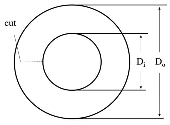
[24][25][27][40,41,57]. Annular metal can be made from metal sheets. Metal sheets are placed under punching machines, and the machine exerts shearing pressure unto the metal sheet to extrude the sheet’s annular geometry, as seen in
Figure 21. After obtaining the annular metal sheet, according to Abdullah et al.
[24][40] and Durrani et al.
[25][41], a straight cut is made on the annulus of the annular metal sheer. The purpose of this cut was to allow the annular metal to be bent in order for it to be reshaped into a helix. The reshaping of the annular metal into a helix requires the use of either a vise bench or a screw-flight-forming apparatus. Bauyon
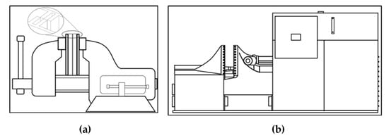
[27][57] used a vise bench to reshape their workpiece into a screw blade, as seen in
Figure 32a. A screw-flight-forming apparatus has been shown to manufacture screw helices, which can be seen in
Figure 32b
[29][59]. The difference between the use of these two apparatuses may mostly depend on the size of the screw blade (e.g., the diameter of the screw blade) desired to be formed; vise benches have been shown to manufacture screw blades of picoscale Archimedes turbines
[29][59], while screw-flight-forming apparatuses were shown to manufacture large screw flights. Although the use of vise bench and screw flight forming are practical methods to manufacture screw helices, these methods may also present some minute irregularities in the dimensions and shape on a component basis.
Figure 21. The annular metal diagram adopted from Abdullah et al.
[24][40].
Figure 32. Apparatus used in screw blade manufacturing: (
a) a vise bench on the left
[27][57] and (
b) a screw flight forming apparatus on the right
[29][59].
Only the work of Walker et al.
[30][60] was found to perform a life cycle assessment (LCA) on the production of AST for tidal energy conversion. The majority of the sustainability assessment of conventional methods of fabricating a turbine blade are all concentrated on wind turbines
[31][32][33][34][61,62,63,64]. Thus, there is an opportunity to assess the environmental impact of conventional methods of manufacturing AST.
2.1.2. Assembly of Archimedes Screw Turbine
A wide array of easily accessible materials are available for the turbine shaft: PVC pipes, typically for plumbing applications, were used as a turbine shaft for the AST
[27][57], and manufacturers can provide various sizes of shafts for the AST. After manufacturing the screw blades and the turbine shaft, the screw blades are attached to the turbine shaft through either welding or fastening based on the reviewed research works
[22][39]. Hindle and Boersma
[35][65] discussed in their patent on the AST that the screw blade is welded onto the turbine shaft. However, there has been no direct comparison between the two methods of attaching the screw blades, but respective advantages have been mentioned. As previously stated, Rohmer et al.
[22][39] discussed the adverse effects of welding on ASTs. On the other hand, fastening by rivets does not have these adverse effects. However, leakage losses can occur since this process does not close the air gaps between the screw blades and the turbine shaft. Therefore, the tradeoff between the adoption of welding over fastening is the avoidance of leakage losses versus susceptibility to corrosion.
2.2. CNC Manufacturing
Manufacturing techniques of computerized numerical control (CNC) machines have not yet been documented for AST manufacturing, but research on the manufacturing of similarly helical-shaped objects has been found. CNC machining is a type of subtractive manufacturing method that uses computerized control to automatically move a working (e.g., rotating) tool that removes metal from a workpiece with very high precision. Programming using NC code is inputted to the controlling unit, which controls the motion of the tool around the workpiece.
Bizzarri and Bartoň
[36][66] highlighted flank machining with the use of CNC machines in manufacturing screw rotors. They mentioned that manufacturing screw rotors is a complex process that requires expensive machinery, and the working tool conventionally makes several passes over a tool path. To optimize this manufacturing process, a specialized approach using a five-axis flanking machine with double-flanking for manufacturing screw rotors was proposed. In this approach, an appropriate shape for the working tool was determined, and the tool’s motion was optimized. All proof and computations were conducted using numerical experiments.
Matejic et al.
[37][67] emphasized the improvements in the CNC machining of progressive screw shafts. The manufacturing of progressive screw shafts using CNC lathe machines and three-axis CNC milling machines had severe limitations. To resolve these limitations, they added a fourth axis to the three-axis CNC milling machine, and they used Autodesk Inventor HSM software for the controlling unit of the CNC machine. With these technological upgrades, the CNC machine can now flexibly manufacture varying designs of progressive screw shafts without custom-shaped tools and complicated functions of the machine.
Although CNC manufacturing has a significant contribution to the production of screw rotors, no research articles were found that used CNC machining to generate an AST. Moreover, no LCA studies were found that evaluated the CNC machining of AST. However, Swetha et al.
[38][68] performed a comparative gate-to-gate LCA on conventional manufacturing via CNC machining and additive manufacturing for a sprocket adapter. Their results revealed that additive manufacturing had a lesser environmental impact compared with conventional manufacturing, such as the CNC machining approach
[38][68].
2.3. Molding Manufacturing
Another method for manufacturing screw blades is conducted through the use of the molding process. A method for using the molding process for forming screw flights was invented by Lapeyre
[39][69]. Molding processes are additive manufacturing techniques that require pouring molten metal or plastic resin into the cavities of specially made casts whose cavities are exactly shaped to the geometry of the desired product
[40][70]. The final product is realized after the molten material temperature cools down and the material solidifies into a mold
[41][71]. Similarly, in a patent for the invention of the AST, Hindle and Boersma
[37][67] outlined the use of molding for manufacturing the AST screw blades. The specific molding processes for ASTs involve injection molding and rotary molding casting. Limited studies are available on these types of manufacturing processes, specifically on ASTs. However, Atkin
[28][58] has used light resin transfer molding to manufacture an industrial AST. It is to be noted that the study considered the comparative evaluation of different manufacturing methods of the screw blade. The results determined that light resin transfer molding was the preferred method in manufacturing the ASTs
[28][58]. It was highlighted that the composite material used in the manufacturing of the AST provided an almost comparable structural performance to steel. Moreover, it was outlined that the composite material is relatively lighter, corrosion-resistant, and provides less friction than steel
[28][58].
No LCA study was found to evaluate the environmental impact of manufacturing an AST using the molding process. The nearest LCA study on the turbine molding process is the work by Upadhyayula et al.
[42][72], which was applied to wind turbines. The functional unit they utilized is a three-blade, off-shore wind turbine. The results showed that the recycled carbon fiber used in the molding process had the optimum environmental impact when compared to the use of virgin carbon fiber. To further understand the impact of the molding process in the life cycle of the AST, an LCA study is suggested.
2.4. 3D Printing
3D printing is a relatively modern technique used in the manufacturing industry that has been reliable in manufacturing products with high precision
[43][73]. It is a form of additive manufacturing in which material is continually added to the workpiece to realize the final product. The physical dimensions of a product are first realized into a CAD model, which generates an STL file format (standard triangulation language) that the 3D printer uses to manufacture the desired product by additively building it with appropriate material
[44][74]. Several researchers have stated that they have used 3D printing to manufacture their AST prototype.
Dellinger et al.
[45][24] studied the structure of 3D turbulent flows and energy losses in the screw of an AST by finding the coefficients within turbulent closure models. They developed a CFD model and manufactured a laboratory-scale AST prototype to compare the results. For the manufacturing method, they only mentioned that the whole prototype was manufactured with Acrylonitrile butadiene styrene (ABS) plastic using a 3D printer.
Zitti et al.
[46][38] performed numerical simulations and experimental investigations of a ductless AST to investigate its efficiency. Their AST prototype’s screw and shaft were manufactured separately using a 3D printer, and both materials were made of polylactic acid (PLA). The parts were then conjoined together using high-performance glue.
Sari et al.
[47][75] presented a review of the various characteristic performances of different AST research works. In one citation, they showed a feasibility study that was carried out on using a 3D-printing machine for manufacturing screws using PLA and epoxy. Their findings were that screws manufactured using PLA and epoxy were cheaper than metal-based manufacturing, but they also warned that PLA-based screws were only reliable for two years.
Shashank et al.
[44][74] theoretically and empirically investigated the performance of a 3D-printed AST prototype. They chose PLA for the material of the AST prototype based on its mechanical properties that are desirable for hydropower generation, namely, melting point, tensile strength, cost, and biodegradability, which make it environment friendly. The CAD model of the prototype comprised the whole AST, and the AST was manufactured using a 3D printer.
A couple of studies were found to have used the 3D-printing method to manufacture ASTs. Straalsund Jerry et al.
[48][76] employed 3D-printing technology to generate various shapes of ASTs for a comparative experimental investigation of various blade shapes, such as strake, reverse strake, and helicoid. On the other hand, Lee et al.
[49][77] utilized the 3D-printing technology via fused deposition modeling to manufacture the controllable pitch blades of the AST. With the use of the 3D-printing manufacturing approach, unconventional blade shapes can be considered for the AST.
Based on these research works, the manufacturing process of ASTs using 3D printing is straightforward. The designer must first determine if the screw blade and shaft of the AST are to be manufactured separately or conjointly. This aspect will affect all downstream processes associated with the manufacturing of the AST. For prototypes in separate parts, CAD models for both screw blades and the shaft will have to be made, and they will have to be conjoined together using high-performance adhesive after 3D printing. For prototypes in one whole entity, a single CAD model is required to be able to generate the 3D-printed model of the AST.
Although 3D printing of turbine blades provides advantages, such as flexibility of the design and consideration of more complex blade configuration, it should be noted that it consumes thermoplastic materials that can cause environmental impacts. These environmental impacts can have an exponential effect on large-scale systems. Recently, Olivera et al.
[50][78] highlighted that the detrimental environmental impact of the utilization of 3D-printed turbine blades reside in the recycling process. This is due to the fact that the thermoset materials used in the 3D-printing process contain fibers that are challenging to recycle while their thermo-mechanical properties degrade
[51][79]. Meanwhile, Serra et al.
[52][80] performed a comparative LCA between additive manufacturing, a type of 3D printing, and precision casting of gas turbines. Their results indicated that additive manufacturing is a relatively sustainable process compared to precision casting, with greenhouse gas emissions being lower by 40%
[52][80]. Additionally, Torres-Carrillo et al.
[53][81] also conducted a comparative cradle-to-gate LCA between selective laser melting, a kind of 3D printing, and investment casting on aeronautical turbine blades. The results of their study revealed that the carbon footprint of additive manufacturing is 4% lower compared to investment casting
[53][81]. With the beneficial environmental results of the 3D-printing process compared with other blade manufacturing processes on different turbine blades, it is suggested that 3D printing be used for ASTs.


