1. Injection of Water to Cool the Intake Air
In recent years, there has been a growth in interest in intake air-cooling systems for gas turbines as a result of the growing demand for power at a low capital cost. This is particularly true during hot months when the average temperature of the surrounding environment is high. The following classifications apply to the many intake air cooling systems that are available:
-
Evaporative coolers that use various media. In order to humidify the air, water is sprayed onto pads of fibers, which the air then passes through. 1—Cooling systems that use spray and foggers. Using nozzles to inject water into the air creates a fog with water droplets ranging in size from 5 to 20 mm in diameter. The systems may be broken down into two distinct categories: (1) saturable systems, in which the air is already saturated before the compressor, and (2) non-saturable systems. 2—Overspray systems. Systems that inject more water than is necessary for saturation. Evaporation of moisture drops in the compression results in the air being cooled.
-
In order to cool the air that is being drawn in, a heat exchanger utilizes either a mechanical vapor compression or absorption chillers. The output of gas turbines may be increased by 15–20%, and their efficiency can be increased by 1–2% if chillers are used (i.e., if energy is retrieved from the exhaust gases of gas turbines). The incoming air may be cooled by a chiller regardless of the temperature of the surrounding environment; nevertheless, purchasing a chiller demands a larger initial expenditure than media and spray coolers do.
Although media coolers and spray systems have a relatively low starting cost, their operational costs are significantly raised by their high water consumption. In order to avoid deposits in the compressor, spray systems are required to use deionized water, while media coolers are allowed to make use of untreated municipal water
[1]. Evaporative media coolers are the most common kind of inlet air cooling system; however, spray systems have seen a significant uptick in use since the 1990s. As a result, the performance of media coolers is restricted by conditions (humidity and temperature of the surrounding environment. Because of this, the power generation of a normal diffusion combustor may be increased by 5–10%, while the efficiency can be increased by 1.6–2.6%, and the nitrogen oxides emissions can be reduced by 10% if a media cooler is used to increase the level of humidity of the incoming air to about 90%. Overspray systems have the potential to improve the power output of a normal diffusion combustor by 11–21%, the efficiency by 1.6–4%, and the nitrogen oxide emissions by 21–41%
[1]. The performance improvements provided by saturated spray systems are equivalent to those provided by media coolers. The increase in power output generation and efficiency that may result from a water-injection-based system depends on the relative humidity and temperature of the surrounding air; however, overspray systems are less susceptible to high humidity levels than saturated spray systems and media coolers. The mass flow rate of extra water in overspray systems generally corresponds to 0.5% to 2% of the mass flow rate of the compressor’s intake air
[2]. When hot water is injected, an aerosol is produced that has a water droplet diameter of between 2 and 3 mm and poses a minor danger of erosion to the compressor blades
[3]. Because the water flashes as it leaves the nozzle, hot water creates droplets that are far smaller than those produced by cold water. When compared to an intake air-cooling system that uses cold water, an over-spray hot water system may function at lower levels of temperature and is not as constrained by high levels of ambient humidity; however, it requires a greater initial investment. Additionally, an overspray hot water system may be able to function at higher ambient temperatures. The temperature of the air and its specific heat capacity are altered when water is injected at the compressor intake for the purpose of air cooling or on-line compressor cleaning. As a consequence, the compressor operates outside of the range for which it was designed, which increases the risk that it will stall
[4]. Despite this, a spray intake air-cooling system has been used on about 600 different power plants
[2]. Both Hartel and Pfeiffer
[5] an White and Meacock
[6] provided models of the impact of overspray on compression operations, as well as references to the work of others in their respective fields.
2. Wet Compression and Spray Intercooling with Water Injection in the Compressor
Wang et al.
[7] conducted a series of experiments to investigate the impacts of injecting streams between compressor stages. Ingistoov et al.
[8] performed an analysis on a water injection device that was placed between stages of a compressor. The system’s primary function was to clear deposits from the compressor blades when it was first developed; however, the power output could be increased by increasing the rate at which water was injected. Zhang et al.
[9] showed a thermodynamic-based model for wet compression that may also be used for wet intake cooling in its scope of applicability. The aforementioned inlet air cooling system with hot water
[3] will be progressed further to the TopHat cycle
[10]. This cycle involves the injection of a significant quantity of water that has been preheated by the exhaust gas from the gas turbine into the compressor. This results in a decrease in the temperature of the compressor outlet and makes it possible for the gas turbine to be regenerated more effectively. A comparison showed that the TopHat cycle had higher levels of efficiency and specific power output than other cycles, such as the combined cycle, the Cheng cycle, and the HAT cycle. The highest level of efficiency that the TopHat cycle could achieve was 57.4%, according to the study (PRZ12, TITZ1200 8C). The researchers that carried out the study came up with a combined cycle efficiency of 57.7% for a big gas turbine, but found it had a TopHat cycle efficiency of 58.2%. It was hypothesized that a more sophisticated version of the TopHat cycle would have an efficiency of more than 60%. According to reports, the investment cost for a major power plant with a TopHat cycle is 20% cheaper than the investment cost for a mixed cycle. The power plant in question generates 350 MWe. An investigation on spray inter-cooling was carried out in the AGTJ-100A gas turbine pilot plant
[11].
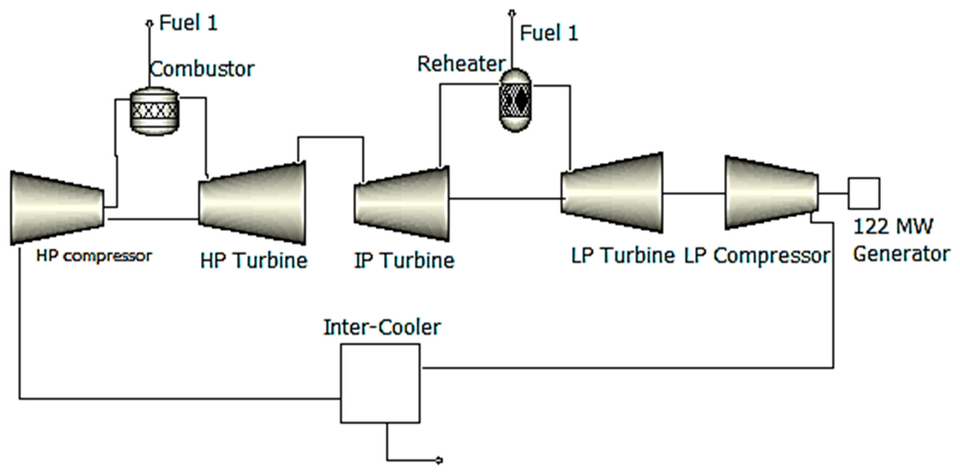
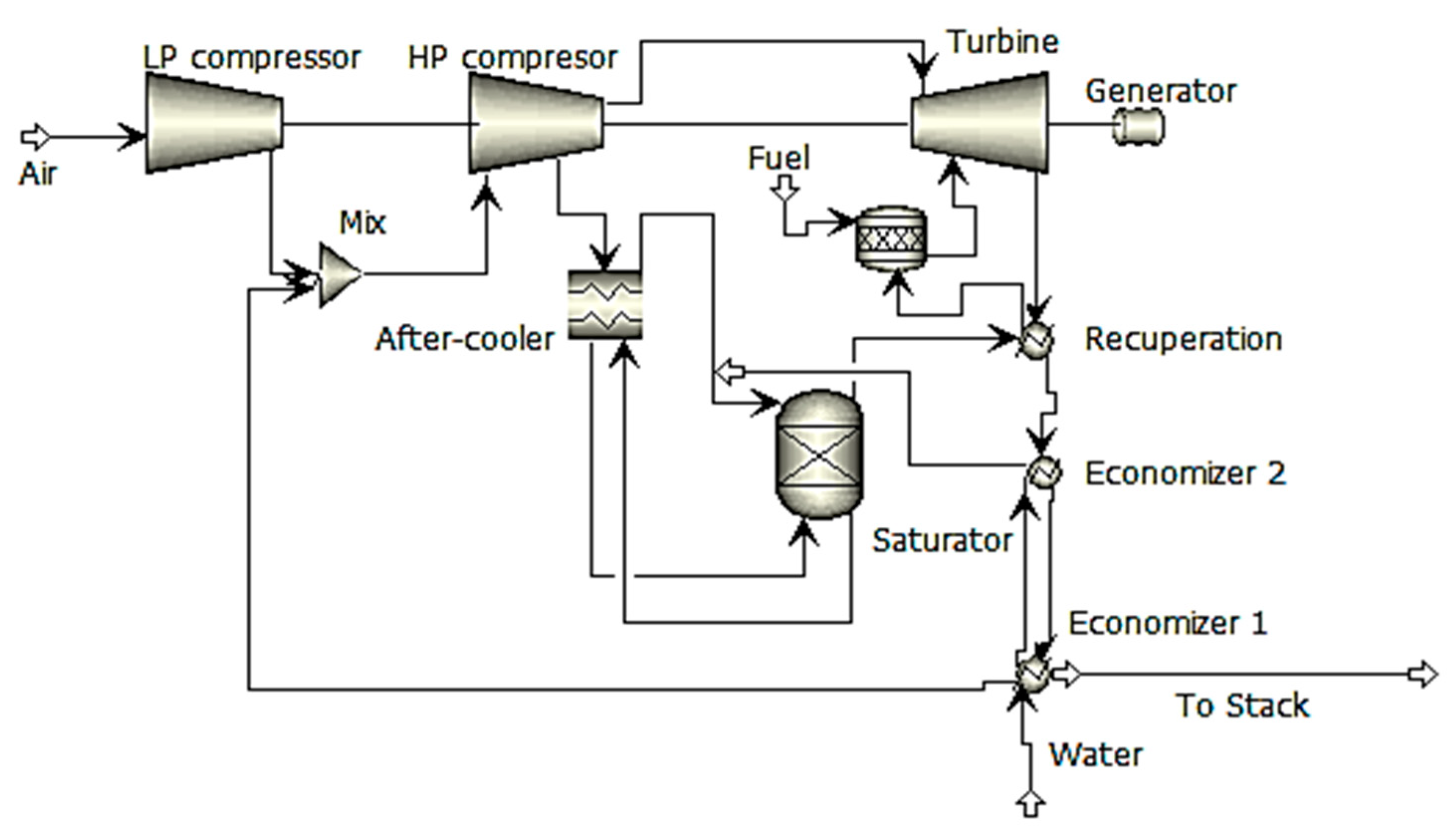
Figure 1 [12] shows that testing of this reheated twin-spool gas turbine started in Japan in 1984. Evaporative inter-cooling was used
[12] in order to increase power generation and efficiency while simultaneously reducing
nitrogen oxides (NOx
) emissions. After passing through the intercooler, the relative humidity reached 90%. The Sprint spray inter-cooling system for the LM6000 gas turbine was developed by G.E. in 1998. This system injects water into the low- and high-pressure compression inlets. The Sprint system improves power generation by more than 8% under ISO criteria and by 33% at 32.8 °C; moreover, gas turbine efficiency is improved at high ambient temperatures
[13].
Table 1 provides a summary of the research efforts on wet compression and spray intercooling with water injection in the compressor.
Figure 1. Schematic of the reheat gas turbine (AGTJ-100A).
Table 1. A summary of the research efforts on wet compression and spray intercooling with water injection in the compressor.
3. Gas Turbines with Recycled Water Injection
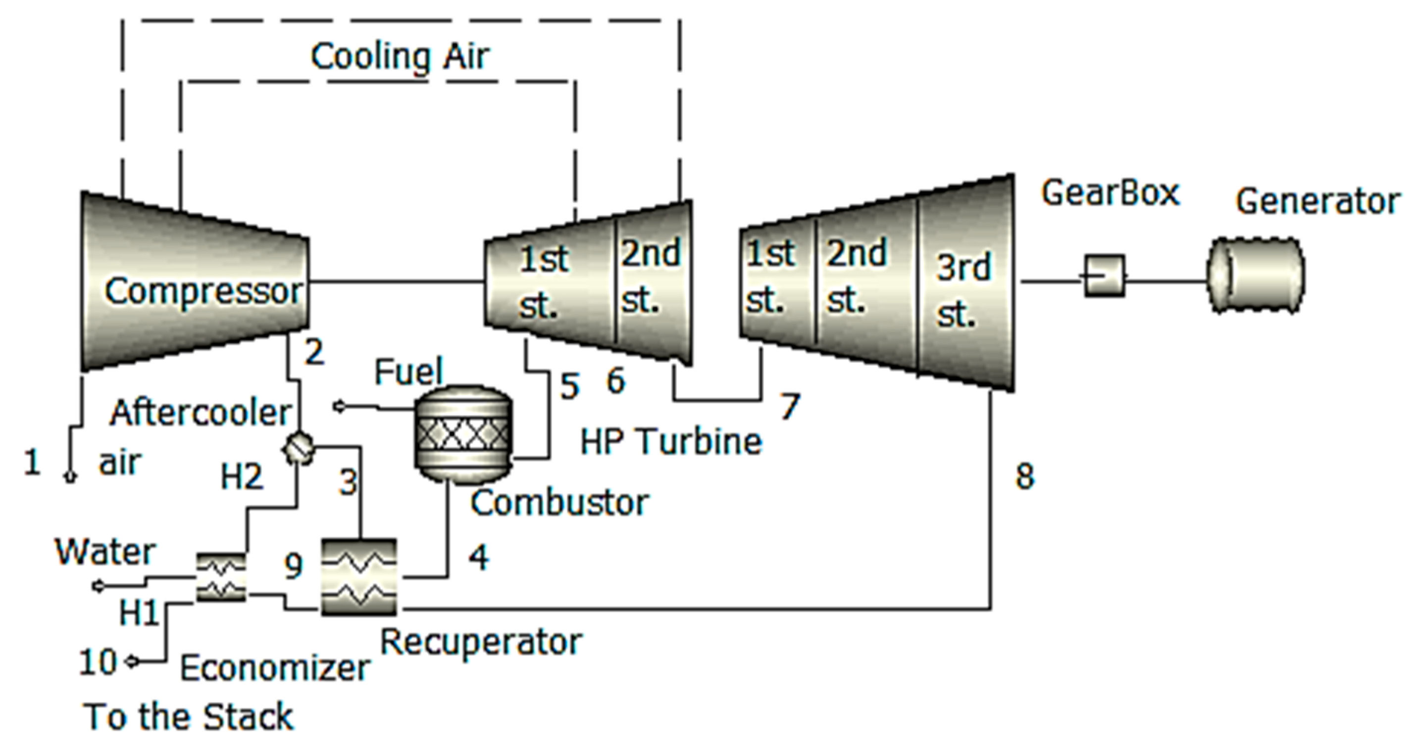
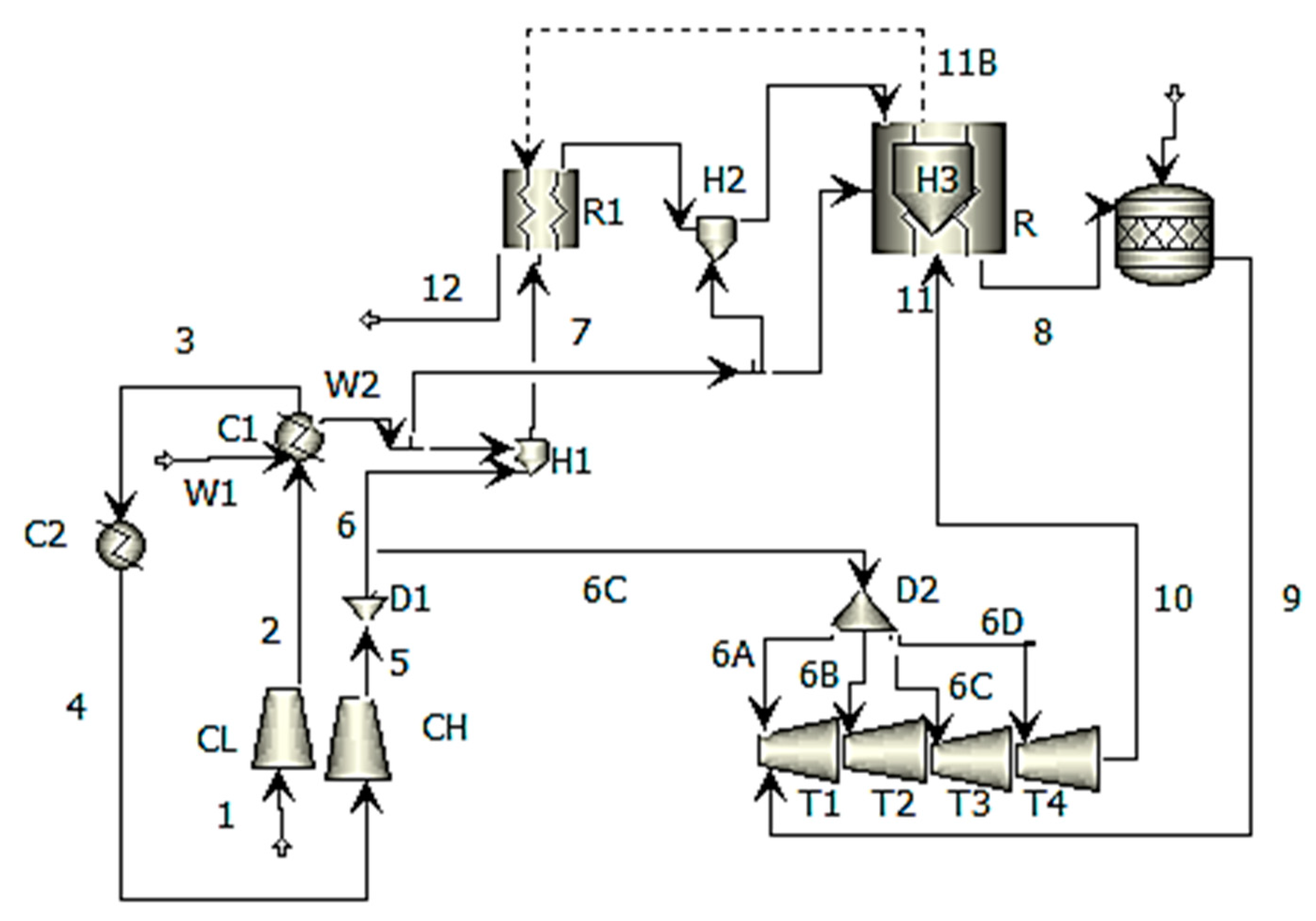
The basic gas turbine with recuperation and evaporative aftercooling is shown in
Figure 2. This process may be altered by injecting water at a variety of locations during the cycle. The effective and efficient recovery of the energy that is being exhausted by the gas turbine is the key focus. It was observed by Najjar and Zaamout
[14] that the fundamental water-injection-based cycle had 58% higher power generation and 13% higher efficiency than recuperation-based configurations that did not include water injection.
Figure 2 is a representation of the recuperated water injected (RWI) cycles that Camporeale and Fortunato
[15] investigated using a two-shaft industrial gas turbine as the basis for their work. The water-injected cycle produced 30% more power than the simple-cycle gas turbine; the water-injection-based cycle (PRZ16.7, TITZ1250 C) was 44.8% efficient, while the simple-cycle configuration was 32.8% efficient. The water-injected cycle produced 30% more power because the water injection rate was equal to 13% of the input air mass flow rate. When compared to the performance of the basic cycle, the performance of the water-injected cycle was greater in terms of power generation and efficiency at partial load and high levels of temperatures.
Figure 2. Schematic of the RWI cycle industrial gas turbine.
The output power and efficiency for an aero-derivative gas turbine were calculated by Camporeale and Fortunato
[16] to be 24 MWe and 46.9 percent for a recuperation-based cycle with water injection (PRZ16.3, TITZ1250 C), and 32 MWe and 40% for a cycle with steam injection. According to these numbers, there is a power output of 31.7 MWe, and the efficiency is 41.1%. (PRZ16.3, TITZ1250 C). Additional research on the expander design of water-injected aero-derivative gas turbines was carried out by Camporeale and Fortunato
[17]. Intercooling-modified basic cycles are another kind of cycle that has been looked at. The recuperation-water-injection-based cycle and steam-injection-based configurations with and without surface intercoolers were the subjects of research conducted by Manfrida et al.
[18]. Because less heat was recovered from the exhaust gas during the water-injected cycles rather than the steam-injected cycles, the water-injected cycles had a lower overall efficiency. In order to achieve a higher rate of heat recovery, the authors suggested using combined cycles that included the introduction of steam from the bottoming cycle into the gas turbine. In order to achieve the highest possible level of efficiency, this system does not inject steam while it is working under base load; nevertheless, when it is working under peak load, steam is injected into the gas turbine in order to boost power generation. The water-injected cycles proved to be the most effective when applied to conditions characterized by low levels of compression and high levels of water injection rates. Because the water injection rates reached up to 20% of the input air mass flow rate, the air in the after-cooler became oversaturated, and the recuperator was responsible for the evaporation of any excess water. According to the assumptions made by Frautschi and Plancherel
[19], a water-injected inter-cooled gas turbine would have an efficiency of 43–45%. Chiesa et al.
[20] estimated an efficiency of either 52.9% (PRZ33, TITZ1500 8C) or 55.1% (PRZ33, TITZ1500 8C) for an aero-derivative surface inter-cooled water-injection-based configuration (PRZ21, TITZ1250 8C). The use of evaporation as a method of inter-cooling resulted in a marginal reduction in efficiency. The after-cooler received an overabundance of water injection in comparison to what was required for saturation, and the recuperator was responsible for removing the surplus liquid. Traverso and Massardo
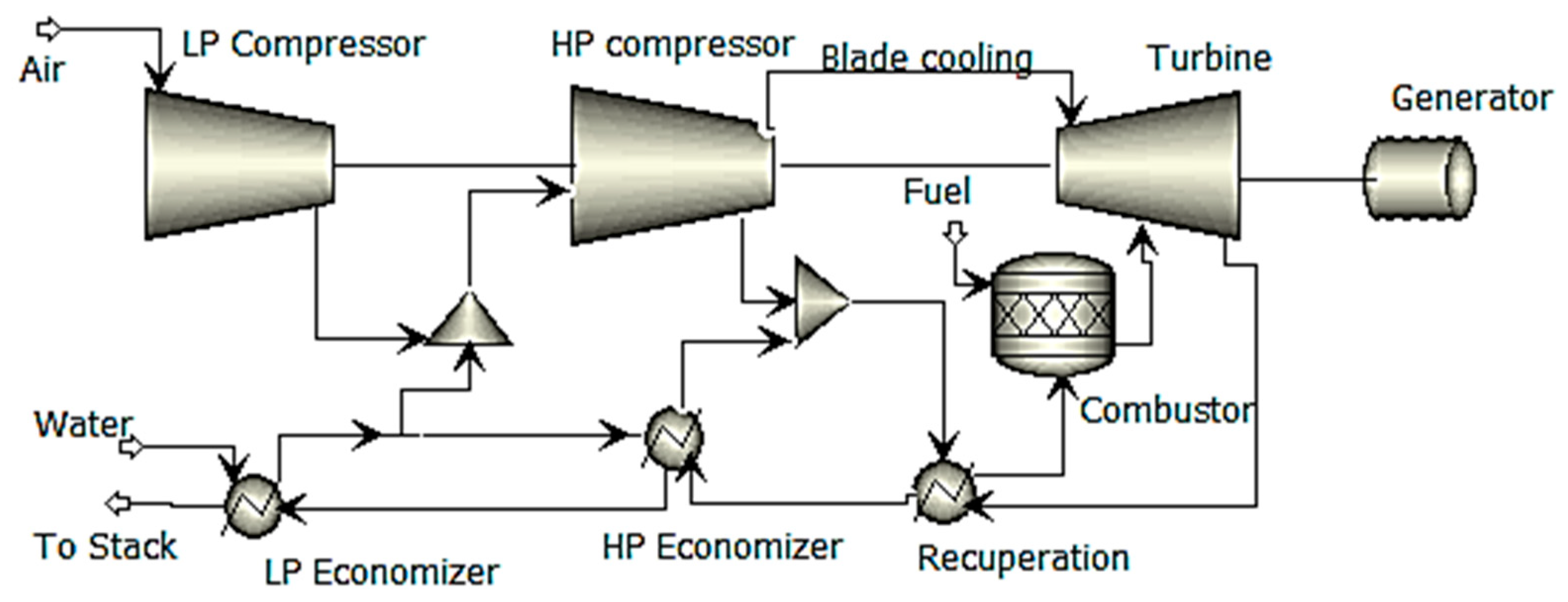
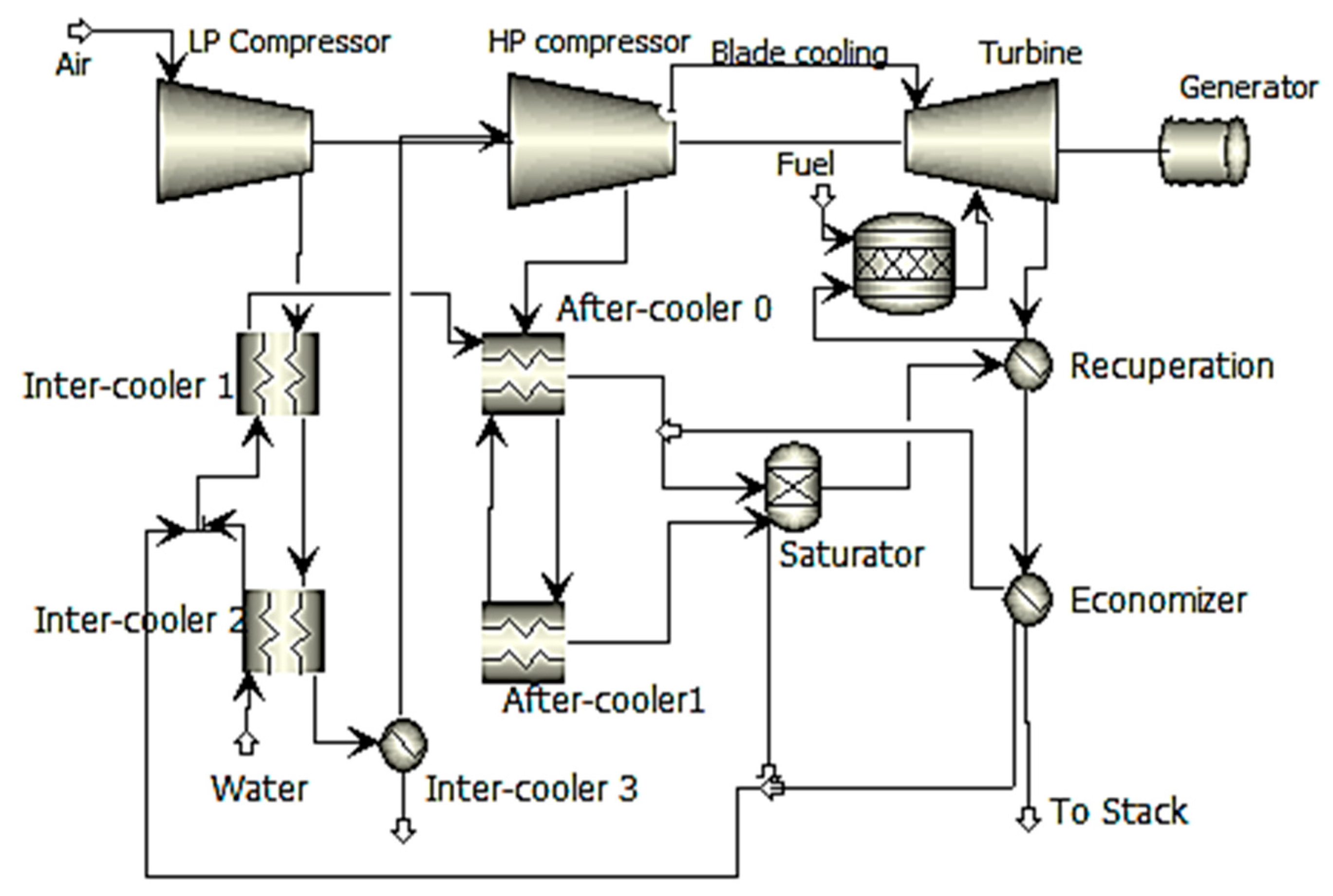
[21] investigated evaporatively inter-cooled water-injected cycles (water injection cycles [RWI], inter-cooled humid air cycles [HAT], and inter-cooled humid air water injected cycle [AWIT],
Figure 3,
Figure 4 and
Figure 5, respectively) with power outputs of around 50 MWe each.
Figure 3. Conceptual plant design for cycles, including inter-cooled water injection (RWI).
Figure 4. Cycles of inter-cooled humid air conceptual plant diagram (HAT).
Figure 5. Conceptual plant diagram for the 3HAWIT cycles of inter-cooled, humid air injection.
The combined cycle, the steam-injected or evaporative gas turbine cycle, and the water-injected cycle all had higher efficiency than the water-injected cycle. This was caused by the air saturation limit on water addition and the high levels of the irreversibility of the air-water-mixing process. Rolls-Royce has investigated the possibility of using a recuperated cycle with a Trent-based engine with water injection for inter-cooling and after-cooling. It was expected that the cycle would have an efficiency of 51%, which is less than a mixed cycle but higher than a basic cycle (42%). The water-injected cycle is expected to offer more flexibility and a particular investment cost that is thirty percent cheaper than that of the combined cycle. Rolls-Royce is of the opinion that there is a large potential for technical risk associated with increasing both the pressure ratio, which is currently set at 35, and the firing temperature; hence, a water-injected cycle is one possibility for improving Trent performance. However, it is projected that the water-injected cycle would have control challenges, and it is also anticipated that the lifespan of the recuperator will be impaired
[22].
One such possible modification is the introduction of water into the recuperator of a gas turbine. With an emphasis on inter-cooling and water injection in the recuperators for open-cycle-based power plant configuration, Horlock
[23] studied both open/closed water-injection-based gas turbines, as well as water injections in the recuperators for closed-cycle gas turbines. According to
[24], the ideal pressure ratio for high efficiency was rather low (i.e., between 8 and 10). Horlock
[25] investigated how successful a recuperator would be with water injection either before or during the process of recuperation. El-Masri
[26] investigated the effects of injecting water into the intercooler, after-cooler, and recuperator of a two-shaft recuperated gas turbine. This cycle had an efficiency that was 2.75 percentage points higher than a non-inter-cooled steam-injection-based gas turbine and five percentage points higher than a non-inter-cooled water-injection-based recuperated cycle, respectively. Without the water injection, the recuperator would have lost around 2% of its efficiency. According to the author, the evaporative after-cooler was easy to build, and it should be possible for water contaminants to pass through the engine unobstructed.
If water is used at a high level of quality, the water-injection-based recuperator might get polluted. In order to prevent the water’s evaporation from having an impact on the recuperator’s walls, it should be injected as a fine mist. A further possible variant of the fundamental water-injection-based cycle is one in which evaporation and recovery occur in many stages. Research by Annerwall and Svedberg
[27] focused on surface inter-cooled reheated power plants with evaporation-based after-cooling, a recuperator, water injection, and a second recuperator. The efficiency reached approximately 53.2%, while the thermal efficiency of a combined cycle was 49.4%, and the thermal efficiency of an inter-cooled recuperated and reheated steam-injection-based cycle was 49.0%. In each cycle, a simple-cycle configuration with a 21,3 MWe power output and a 32.5 percent thermal efficiency was employed (PRZ13.5).
Table 2 provides a summary of the key efforts in developing gas turbines with recycled water injection.
In addition, Sargent
[28] conducted research on a water-injected gas turbine with the goal of using it for district heating and electricity cogeneration. An inter-cooling process with two stages was used throughout this cycle (
Figure 6). The injection water was heated during the first step, while external cooling water was utilized during the second stage.
Figure 6. Scheme of the humid-air heat-and-power plant.
After the compression stage, steam was introduced for after-cooling, the air was recovered once more, and then water heated by the exhaust gas was injected, followed by additional recovery. When compared to single-stage injection, multi-stage injection enabled the incorporation of a greater quantity of water without resulting in the loss of any water droplets inside the recuperator. Because of the large proportion of water in the exhaust gas, the dew point was raised, which resulted in an increase in the amount of heat produced by the district heating system. Szczygiel
[29] also studied configurations with a one-stage injection
[28] and multi-stage injection
[29], with or without an external after-cooler, and extraction of expander cooling air from a variety of cycle points
[28].
Alterations to the fundamental idea that are more substantial, such as separating the stream of compressed air for increased heat recovery, have also been proposed. One cycle for the elimination of the low air–water mixing exergy was proposed by Mori et al.
[30], and it included the use of direct water injection. The other cycle involved the use of a humidification tower. The process of intercooling was broken down into two phases, and the second stage used a water-cooled intercooler that was a part of the direct water-injected cycle. After passing through the surface after-cooler, the air stream was then segmented into three separate streams, and the second intercooler injected hot water into each of those streams. The resulting humid air streams were mixed and then sent through a second recuperator after being routed in parallel via a first intercooler, an after-cooler, and a recuperator. The original recuperator was not a conventional heat exchanger since it caused water to evaporate. As a result, the cycle that included a humidification tower was considered to be technically more realistic, as indicated in the source
[31]. The water-injected cycle that Mori et al.
[30] patented was quite similar to the cycle that Nakamura et al.
[32] patented, with the exception of one crucial difference; the air supply was divided immediately after the compression stage. In accordance with the cycle outlined by Mori et al.
[30], only a part of the stream was sent through the use of the heat-recovery method. The remaining component of the stream was bypassed and instead mixed with moist air before being sent to the third and final recuperator. The efficiency of the humidification system was 50.4% when just 27.9% of the air supply was transmitted through the system, and it was 51.2% when 53% of the intake air was transported through the system. (TITZ1000 8C). A water-injected part-flow cycle that required fewer components was invented and patented by Nakamura
[33]. During this cycle, one of the streams that were formed as a result of the split in the compressor was aftercooled evaporatively and reclaimed before being mixed with the stream that contained dry air and went through further recuperation. In addition, patents were granted for a design that used evaporative intercooling and aftercooling for each and every portion of the compressed air. Nakamura
[34] demonstrated a recuperation-based gas turbine in which the air supply was inter-cooled in a two-stage approach: initially in a heat exchanger and secondly by injection of intercooler-heated water. This process was carried out in a recuperated gas turbine. In addition to that, hot water was injected into the fuel as well as the compressed air so that it could be after-cooled. Exergy and pinch analysis were used by Bram and de Ruyck
[35] in the development of a humidified cycle that was similar to the HAT cycle but did not include a humidification tower. In a similar vein, the procedure described in reference
[36] was quite comparable. The fact that the energy from the second inter-cooler was not added back into the cycle was the fundamental distinction between this cycle and the water-injected cycle that Mori et al.
[30] developed. The net efficiency of this cycle was equivalent to that of an evaporative cycle that included a humidification tower (54%).
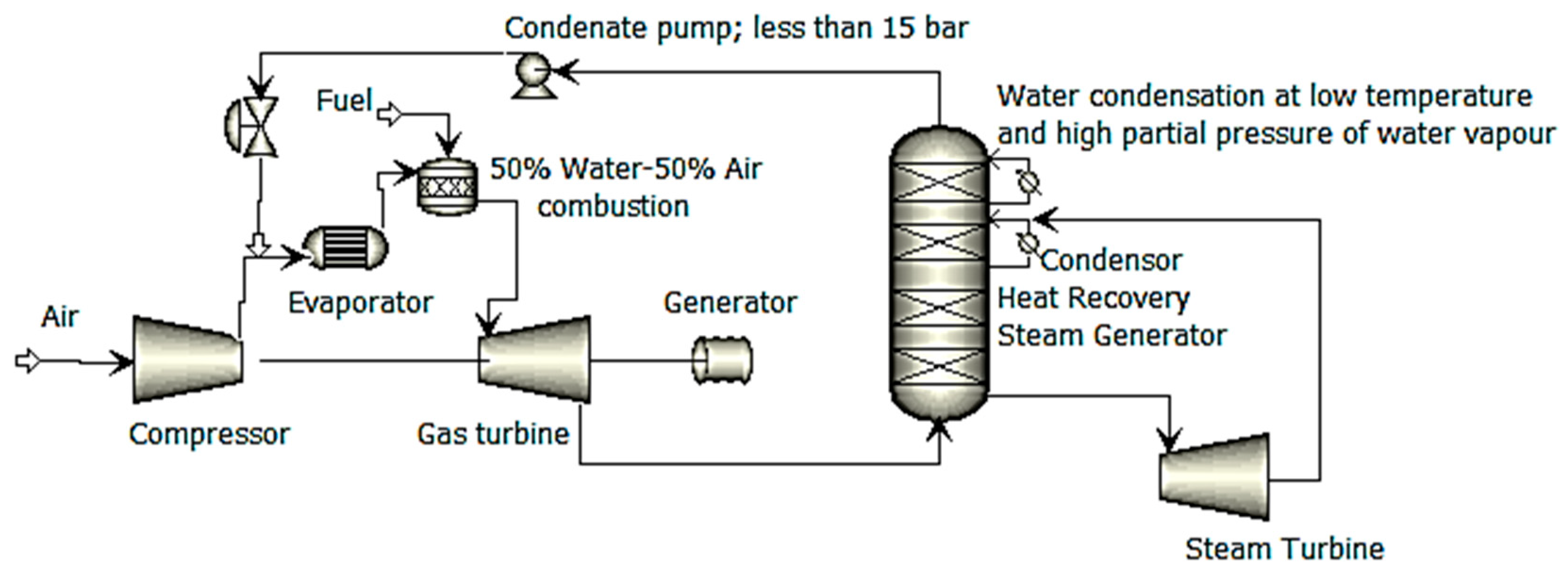
Research has also been carried out on a variety of cycle combinations. A combined cycle with water injection is shown in
Figure 7 of Aronis and Leithner’s
[37] paper. This cycle was called the low-temperature heat combined (LOTHECO) cycle. Following the gas turbine compressor, the water was fed onto a heat exchanger, where it was subjected to the energy of a low temperature (below 170 degrees Celsius), causing it to evaporate. The low-temperature energy might have originated from the combustion of biomass, the sun, geothermal energy, or even the waste heat from industrial processes. As a result of water rather than air lowering the combustion temperature to the permitted turbine intake temperature, the gas turbine fuel was able to be burned at stoichiometric conditions, which caused a decrease, as a consequence, in the amount of work required for compression. Because the exhaust gas included a significant amount of water, condensation formed at temperatures that were suitable for the district heating system. Alterations to the cycle included super-heating the humidified air or utilizing an external heat source to super-heat the humid air before passing it through the evaporator in order to aftercool the compressed air that was to be used in the evaporator. Dodo et al.
[38] created a unique recuperation-based water-injected power unit for the cogeneration of electricity and hot/cold water. An absorption refrigerator is used in this system to capture the energy that is released from the exhaust gas. Depending on the conditions of the working environment, the compressor input might be cooled with cold water from the chiller, or the aftercooling could be achieved with hot water.
Figure 7. Simplified plant scheme of the low-temperature heat combined (L.O.T.H.E.C.O.) cycle.
El-Masri
[39] developed a cycle in which the temperature of humidified air was increased by flue gas in a heat exchanger while compressed air was aftercooled by water injection. Then, before further recuperation, the humid air was coupled with saturated steam created from the energy of the exhaust gas. The cycle’s efficiency might potentially be improved further by inter-cooling it with water injection. Dual-pressure-combined-cycle configurations were slightly more efficient than the suggested cycle, which was more efficient than steam-injected cycles. Dual-pressure combined cycles were marginally more efficient than steam-injected cycles. Adjustable cogeneration of electricity and steam is made possible by the utilization of a variable amount of the energy contained in the exhaust gas for recovery and steam production. A modified version of the intercooler cycle developed by El-Masri
[39] was investigated by Bolland and Stadaas
[40] for the purpose of power generation using only the most cutting-edge gas turbines that are now on the market. In this variation of the cycle, the steam is super-heated before it is injected into the combustor. This is in contrast to the traditional cycle, which involves combining saturated steam with moist air prior to the final heat exchanger. For the power units that were put through the study, a steam-injection-based cycle was 9–11% more efficient than a basic cycle, while the suggested cycle was only 3–4% more efficient than a steam-injection-based cycle. The efficiency of big industrial gas turbines was highest with a triple-pressure combined cycle, which ranged from 52–55%, followed by the cycle that was presented (50%), and then a steam-injection-based cycle (44.9–45.9% efficient). The difference in efficiency between a combined-cycle configuration and the proposed configuration was minimal for medium-sized industrial and aero-derivative power units. For small-scale power units (4–6 MWe), the efficiency of the suggested cycle was equivalent to or greater than that of a single-pressure-combined cycle.
According to the published research, there was going to be one demonstration plant in which water was going to be pumped directly into a power unit after the compression stage. This plant was going to be at the Vrije Universiteit in Belgium, and it was going to be used for integrated power production and district heating. In this particular gas turbine, the compressed air was heated using gasified biomass that had been burnt in an external combustor together with the exhaust gas from the gas turbine. This process took place in a metallic heat exchanger. The heat exchanger could boost the air temperature to 800 degrees Celsius, which would make it possible to add natural gas topping combustion and bring the temperature of the turbine input up to 1000 degrees Celsius. It is possible to inject heated water into the external heat exchanger before it is used. This would result in enhanced power production and efficiency, as well as changeable power-to-heat ratios. The calculations showed that the power production would be 300 kW without water injection and topping combustion, while the heat output would be 1200 kW (thermal efficiency 13%, overall efficiency 65%). However, water injection of 8.5% by weight would improve the power output to 565 kWe (efficiency 21.5%). The output would be 800 kWe (with a 26 percent efficiency rate) if water injection and super-heated combustion were used.
[41]. Despite this, the authors of this research were unable to find any literature that discussed the operation of this facility in relation to water injection. Bechtel and Parsons
[42] received a patent for a similar gas turbine that was water-injected and externally fired, although it did not include topping combustion. Another cycle that has been proposed
[43] is known as the VAST cycle, which stands for vapor, air, and steam in combination with a turbine. Despite this, the designer asserts that the cycle circumvents the HAT and evaporative cycles’ saturation restrictions, resulting in higher specific power and reduced costs. The cycle, according to the inventor, also gets over the traditional limitation on water injection brought on by flame stability.
4. Nitrogen Oxides Management Using the Combustor Injection of Water or Steam
It is possible to lower the amount of NOx that is produced by the combustor by injecting water or steam into it
[44]. It was first suggested in the early 1960s
[45], and up until the middle of the 1990s
[46], it was the NOx control technique that saw the most widespread use. The production of thermal NOx is the principal contributor to the emission of NOx by gas turbines. Because temperature and residence time are the determining factors in the creation of thermal NOx, lowering the temperature of the combustion zone by adding a diluent such as water or steam might result in a decrease in the amount of NOx that is produced
[47]. The generation of extra power is an additional advantage of injecting water or steam; however, the efficiency of the process is diminished if the energy from the exhaust gas is not collected and used to warm the water or generate the steam that is injected. Because the required evaporation energy is obtained from the fuel, steam injection impacts efficiency less than water injection; also, for the same NOx reduction effect, less water is needed compared to steam
[47]. Water injection has a greater influence on efficiency than steam injection. In most cases, an amount of water equal to about fifty percent of the fuel mass flow rate and an amount of steam equivalent to one hundred to two hundred percent of the fuel mass flow rate are injected
[46]. Dry burners that produced minimal levels of NOx were introduced at the beginning of the 1990s. Because of the lean nature of the combustion that takes place in these burners, both temperature and the generation of nitrogen oxides are reduced. Both wet
[47] and dry
[46] systems have the potential to reach nitrogen oxides levels of 24 ppmvd [parts per million by volume, dry]. Mathioudakis
[48] presented a method for conducting an analytical approach to analyze the effects of injecting water into the combustor of a gas turbine on the amount of power produced and the amount of efficiency gained.