Triply Periodic Minimal Surfaces (TPMS) are a kind of periodic implicit surface with zero mean curvature, that is, the surfaces that locally minimize surface area for a given boundary. The TPMS is composed of infinite, non-self-intersecting, periodic surfaces in three principal directions. The TPMS networks as repeated lattice structures have attracted much research interest because they have shown better mechanical performance, mass transfer, and thermal conductivity than conventional and strut-based structures, which have been employed in different disciplines. With excellent performances in the TPMS architectures, current works have investigated the TPMS structures to utilize in a wide range of applications.
- triply periodic minimal surfaces
- internal cooling
- heat transfer
1. Introduction
Additive manufacturing (AM) reduces the limitations in the fabrication of complex lattice structures. A variety of design tools are rapidly developed to facilitate the design of cgeometrically complex structures and allow designers to realize complicated models. Weight, volume, and manufacturing cost reductions are some benefits of AM over conventional manufacturing [1][2][3][4]. Among the lattice structures, architected materials with topologies based on Triply Periodic Minimal Surfaces (TPMS) have attracted much attention due to their mathematically controlled topologies and their excellent physical and mechanical properties.
The TPMS is composed of infinite, non-self-intersecting, periodic surfaces in three principal directions. Schwarz discovered the first example of TPMS, namedwas the Diamond minimal surface (Figure 1a), in 1865 [5]. Later, his student, Neovius, discovered the Neovius surface (Figure 1b) in 1883 [6]. They further discovered several minimal surfaces, e.g., the Primitive (Figure 1c). Almost a century later, in 1970, Schoen introduced various types of minimal surfaces, and the Gyroid minimal surface (Figure 1d) was [7]the most famous [7]. The TPMS is characterized as a minimal surface becausince the curvature along the principal curvature planes is equal and opposite at every point, resulting in a zero mean curvature of zero.
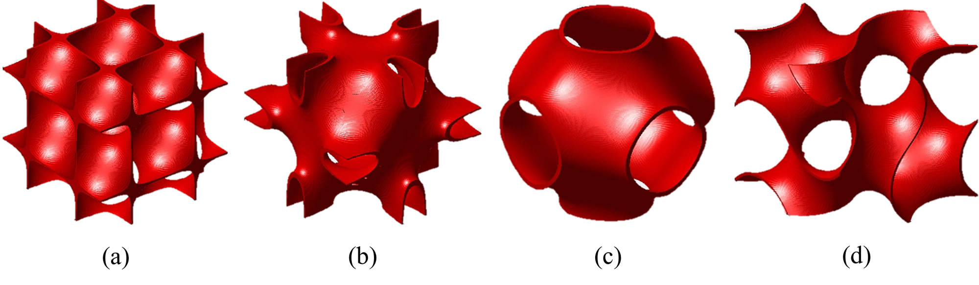
Figure 1 Minimal surfaces (a) Diamond; (b) Neovius; (c) Primitive; (d) Gyroid.
The TPMS is composed of infinite, non-self-intersecting, periodic surfaces in three principal directions. Schwarz discovered the first example of TPMS was the Diamond minimal surface (Figure 1a) in 1865 [5]. Later, his student, Neovius, discovered the Neovius surface (Figure 1b) in 1883 [6]. They further discovered several minimal surfaces, e.g., the Primitive (Figure 1c). Almost a century later, in 1970, Schoen introduced various types of minimal surfaces, and the Gyroid minimal surface (Figure 1d) was the most famous [7]. The TPMS is characterized as a minimal surface because the curvature along the principal curvature planes is equal and opposite at every point, resulting in a mean curvature of zero.
The level-set equation, derived from satisfying the equality criterion ϕ(x,y,z)a sum defined in terms of the Fourier = c, is the most widely usemployed method to create minimal surface-like lattices. The level-set equations of are a group of three-dimensional trigonometric functions that satisfy the equality criterion ϕ(x,y,z) = c. The level-set equations of Schwarz-Diamond (Diamond), Schoen-Gyroid (Gyroid), and Schoen-I-graph and Wrapped Package (IWP), investigated in mosttypically found in the literature, are showndescribed in Equations (1–3).
Diamond: cos(2
α
π
x
)cos(2
β
π
y
)cos(2
γ
π
z
)−sin(2
α
π
x
)sin(2
β
π
y
)sin(2
γ
π
z
) =
c
(1)
Gyroid: sin(2
α
π
x
)cos(2
β
π
y
) + sin(2
β
π
y
)cos(2
α
π
x
) + sin(2
γ
π
z
)cos(2
α
π
x
) =
c
(2)
IWP: 2(cos(2
α
π
x
)cos(2
β
π
y
) + cos(2
β
π
y
)cos(2
γ
π
z
) + cos(2
γ
π
z
)cos(2απx)−(cos 2(2
α
π
x
) + cos 2(2
β
π
y
) + cos 2(2
γ
π
z
)) =
c
(3)
where α, β, and γ denote constants related to the unit cell size (L) in x, y and z, respectively; c is the offset parameter, which equals zero for a single unit cell of the TPMS.
Thewo TPMS-based latticapproaches can be constructed using two methods based on the minimal surfaces. The solid-based Tcreate the TPMS lattice, also known as the skeleton-based TPMS structure (Figure 2s based on the minimal surfa), can be created with thes. The first approach that is achieved by considering the volume bound by the minimal surface. The sheet to create the solid-based TPMS lattice, also known as the skeleton-based TPMS latticstructure (Figure 2ba) is t. The second one that is generis created by offsetting the minimal surface along its normal direction. With mathematical realized, the TPMS to create a double surface. This surface is known as the sheet-based struc TPMS lattice (Figure 2b). Witurh thes have smooth curvature, whichs, the TPMS-based structures can eliminate the stress concentrations commonly found in other structures.
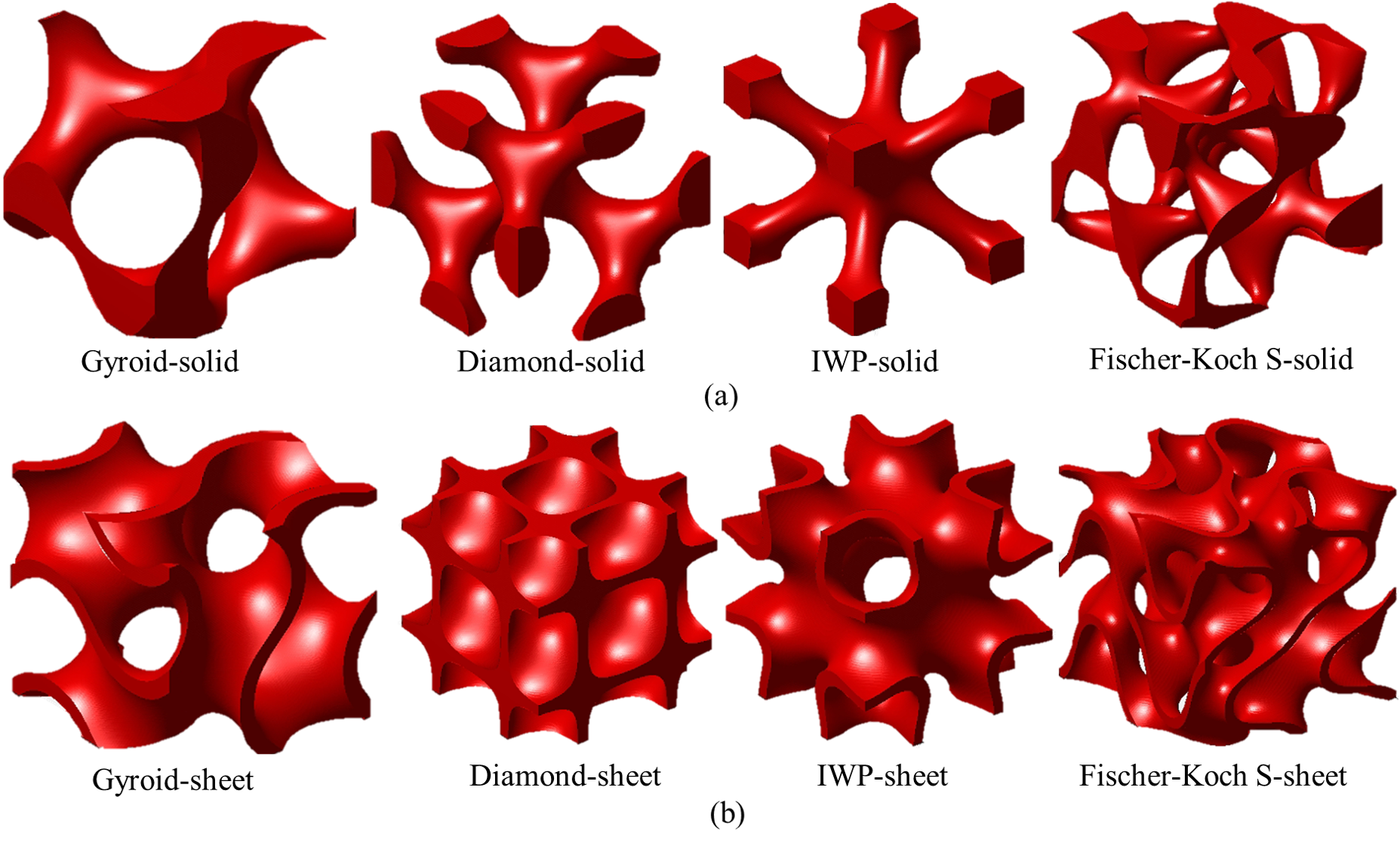
Figure 2 Examples of solid- and sheet-based TPMS lattices.
2. TPMS-Rrelated Iinvestigations
2.1. Mechanical Pperformances
To demonstrate the merits of the TPMS-based structures, the performances of the TPMS-based structure have been examins are analyzed and compared with other conventional structures. The majority of studiAmong the performances in variousdifferent fields have investigated , most of the research has focused on mechanical performances. Speirs et al. [8] [8] reported that due to no nodal points in the TPMSTPMS-based structures, they outperformed t acquired superior fatigue resistance compared to the octahedron unit in terms of fatigue resistanceowing to smooth surfaces without nodal points. Khan et al. [9] demonstrated that in comparison to conventional lattice-frame materials, tthe sheet-IWP structures gaveexhibited superior viscoelastic behaviors under uniaxial loading than other lattice-frame materials. Wang et al. [10] presented that when compared to cubic and octet-strut-based designs, tthe sheet-Gyroid structure obtained the best stability and presenexhibited the widest varietyrange of mechanical properties. Teng et al. [11] compareported that in terms of stiffness, yieldo cubic and octet-strut-based structures. Teng et al. [11] sreportress, and toughness,ed that the sheet-Gyroid structure outperformed better than ththe BCC and truss lattices, as s structures in stiffness, yield stress, and toughness, as shown in Figure 3. Overall, the TPMS-based lattices outperform strut-based strustructures in terms of provide better mechanical performance. As a result than the strut-based structures. Thus, the TPMS-based structures, particularly those based on sespecially the sheet-based ones, can be usemployed in a variety of different disciplines that demandrequiring high mechanical strength.
![Normalized mechanical properties of the Gyroid, BCC, Truss and Primitive lattices with respect to the wall thickness, adapted from [11].](/media/item_content/202212/figure3-63a55d0c8fa8a.png)
Figure 3
Normalized mechanical properties of the Gyroid, BCC, Truss and Primitive lattices with respect to the wall thickness, adapted from Teng et al. [11]
2.2. Mass Ttransfer
The TPMS structures hare suitablve interconnected curved walls with non-tortuous pores, which are appropriate for mass transfer appnd permeability applications because they have continuously curved walls and non-tortuous pores. From the flow perspective, previous studies have focused on permeability and wall shear stress. Still, the flow considered in these investigations was mainly achieved in the Darcy regime, and the non-linear inertial effects were negligible. Ali et al. [12] reported that the sheet-Gyroid structure prshovided comparable fluid permeability but wed higher wall shear stress than the lattice-based models in the same porosity but generated comparable fluid permeability. Montazerian et al. [13] [13] studied cylindrical ducts of different lattice- and TPMS-based scaffolds. They showed that the TPMS-basolied scaffolds, especially the solid-IWP structure was, were more permeable than different lattice-based modelones in the longitudinal fluid flow direction, as presented in Figure 4. Also, the TPMS-based scaffolds within a wide range of porosity, the TPMS-based scaffolds showed larg exhibited higher normalized permeability values than the fiber-based modelstructures [14]. AlEven though the permeabilityorosity of the fiber-based structure increased with the porosermeability, the tortuosity of the fiber-based structure dramaticalwas significantly decreased [15], which hnegad a detrimental effect ontively affected the fluid mixing and heat transfer performance.
![Normalized longitudinal permeability versus porosity for different lattices, adapted from Montazerian et al. [13].](/media/item_content/202212/figure4-63a673e10aa09.png)
Figure 4 Normalized longitudinal permeability versus porosity for different lattices, adapted from Montazerian et al. [13][13].
2.3. Thermal Cconductivity
TMany designers have tested the thermal conductivity of different TPMS-based structures has been tested by many designers. According to the experimental investigationresults by Wang et al. [16], the sheet-FRD strucompared totures achieved 103% higher thermal conductivity than the commercial stochastic foams with the same porosity, t. The sheet-FRDTPMS structures achieved 103% highlso provide better thermal conductivity. It has been also observed by Ni et al. [17] than the fiber-based structure since that the normalized thermal conductivity values of the fiber-based porous media considerably varied with the fiber direction; hence,[17]. tThe sheet-based TPMS structures can also provide bettmain reason for the higher thermal conductivity thain the fiber-based models. The connection of the curved wall in the TPMS-basedsheet-TPMS structures was the main factor in excellent thermal conductivityconnectivity of the interconnected curvature.
Also, it has been reported that the TPMS topologies have a significant impact on efffective thermal conductivity strongly depends on the topologies. Qureshi et al. [18] presented that the sheet-Primitive structure exhibited the highest value, followed by sheet-IWP and sheet-Gyroid structures, whileereas the Kevin cell model caused the lowest value. Smith et al. [19] [19] concluded that the thermal conductivity of the TPMS-based lastticructures was inversely proportional to the surface area-to-volume ratio. However, the thermal performance of cooling channels was typically proportional to surface areas for convective heat transfer. Overall, the thermal conductivity for most sheet-TPMS structures is similar, significantly higher than conventionally stochastic metal foams and lattice-frame materials, as shown in Figure 5.
![Normalized thermal conductivity for different lattices. Octet [20], Rhombi-Octet [21], Solid-Gyroid [22], Solid-Primitive[22], Sheet-CLP [22], Sheet-Neovius [22], Sheet-Fischer Koch S [22], Stochastic metal foam (Al) [23], Stochastic metal foam (FeCrAl) [24].](/media/item_content/202212/figure5-63a677d57d6d9.png)
Figure 5 Normalized thermal conductivity for different lattices, adapted from Kaur and Singh [2]. Octet [20], Rhombi-Octet [21], Solid-Gyroid [22], Solid-Primitive [22], Sheet-CLP [22], Sheet-Neovius [22], Sheet-Fischer Koch S [22], Stochastic metal foam (Al) [23], Stochastic metal foam (FeCrAl) [24].
Normalized thermal conductivity for different lattices. Octet [20], Rhombi-Octet [21], Solid-Gyroid [22], Solid-Primitive [22], Sheet-CLP [22], Sheet-Neovius [22], Sheet-Fischer Koch S [22], Stochastic metal foam (Al) [23], Stochastic metal foam (FeCrAl) [24].
2.4. Forced Cconvective Heat Theat transfer
ThUnlike TPMS-equipconventional pin-shaped heat sinks ha, the heat sinks with TPMS structures have a more complex geometry than typical pin-shaped heat sinks, caus, forcing the fluid to change trajectory as it passesflows past the heated sectionarea [25][26]. The large surface area per unit volume, smooth curved wall, and complicatedex topology ofqualify the TPMS-based structures are preferable forto be examined as high-performance heat sinks. Moreover, the being mathematically realized, the complexity level of the TPMS-based heat sinks can be controlled to enhanceoptimize thermal performance.
To since they are mathematically realized.
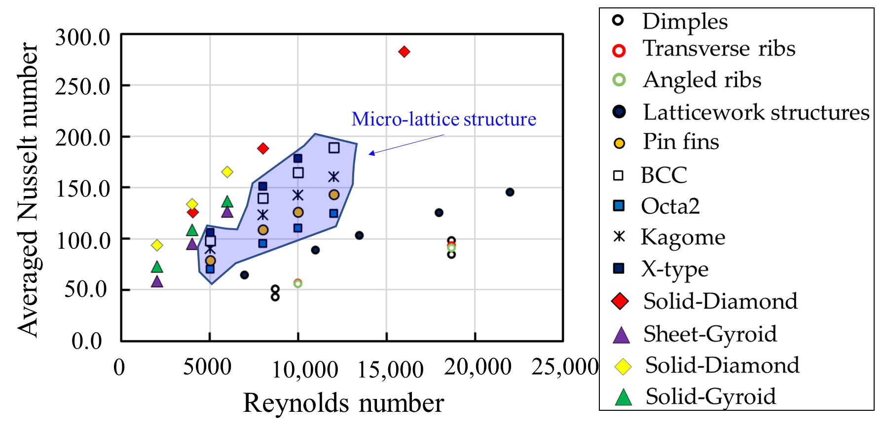
Tompare the heat transfer performance of TPMS-based structures, the globally averaged Nusselt number (Nu) of the TPMS-based structures and different cooling geometries are plotted in, including Figure 6 to codimpales [27], reibs the[28], helat transfer performance.ticework structures It[29], pis evidentn fins [21], that in comparison to thend micro-lattice structures [21], is plothter coolingd in Figure 6. It is geometries,vident that the TPMS-based structures exhibitshow higher globally averaged Nusselt numbers, particularespecially for the solid-Diamond sand solid-Gyroid structurees than the other cooling geometries. At the Reynolds number (Re) of 8000, the globally avalueeraged Nusselt number for the solid-Diamond structure is much hhigher than the micro-pin fins, BCC, Octa, Kagome and X-type lattice sts by about 73%, 35%, 98%, 53% and 25%, respectively. Among the TPMS-based structure. Ts, the sheet-Gyroid structure causes the lowestshows low values among the TPMS-based lattices. Tof the globally averaged Nusselt numbers. On average, the solid-Diamond and solid-Gyroid lattices, on average, performstructures outperform the sheet-Gyroid structure by 1.27 and 1.23 times better than the sheet-Gyroid structure. This increase is due to the higher surface area intersecting the flow field. However, it has been observed that the sheet-Gyroid structure shows higher values than thoutperformed the solid-Gyroid structure at Re > 6800, dueattributed to the strongenhanced fluid mixing in the sheet-Gyroid structure.
![Comparisons of globally averaged Nusselt number of the TPMS structures with other cooling strategies. Dimples [27], Transverse ribs [28], Angled ribs [87], Latticework structures [29], Pin fins [21], BCC [21], Octa lattices [21], Kagome lattices [21], X-type lattices [21], Solid-Diamond structures [30,31], Sheet-Gyroid structures [31], Solid-Diamond structures [31], Solid-Gyroid structures [31].](/media/item_content/202212/figure6-63a6784df270f.png)
Figure 6 Comparisons of globally averaged Nusselt number. Dimples [27], Transverse ribs [28], Angled ribs [28], Latticework structures [29], Pin fins [21], BCC [21], Octa lattices [21], Kagome lattices [21], X-type lattices [21], Solid-Diamond structures [30][31], Sheet-Gyroid structures [31], Solid-Diamond structures [31], Solid-Gyroid structures [31].
Comparisons of globally averaged Nusselt number of the TPMS structures with other cooling strategies. Dimples [27], Transverse ribs [28], Angled ribs [28], Latticework structures [29], Pin fins [21], BCC [21], Octa lattices [21], Kagome lattices [21], X-type lattices [21], Solid-Diamond structures [30][31], Sheet-Gyroid structures [31], Solid-Diamond structures [31], Solid-Gyroid structures [31].
The globally averaged Nusselt number ratio plotted agawinstth friction factor ratios for different geometries is shownare plotted in Figure 7 to compare the relative thermal performance of the cooling structures. The results show with friction factor ratios between 55.0 and 75.0, tthat the solid-Diamond structure achievequires the highest Nusselt number ratio, up to 8.0-10.0. In comparison to the solid-Diamond structure, t–10.0, with friction factor ratios between 55.0–75.0. The solid -Gyroid structure exhibitcauses lower Nusselt number ratios with comparableto the solid-diamond structure with similar friction factor ratios. Compared to micro-lattice structures, tThe sheet-Gyroid structure producgenerates higher Nusselt number ratios and greater friction factor ratios. The ribs and dimples produce minorthan the micro-lattice structures but causes high friction factor ratios between 1.2 and 3.0 while providing . Meanwhile, the dimples and ribs give the lowest Nusselt number ratios, which range from 1.5 to 2 of about 1.5–2.0 while producing minor friction factor ratios between 1.2–3.0.
![Relative thermal performance for different cooling structures. Dimples [27], Transverse ribs [28], Angled ribs [87], Latticework structures [29], Pin fins [21], BCC [21], Octa lattices [21], Kagome lattices [21], X-type lattices [21], Solid-Diamond structures [31], Sheet-Gyroid structures [31], Solid-Diamond structures [31], Solid-Gyroid structures [31].](/media/item_content/202212/figure7-63a678bdc8fb3.png)
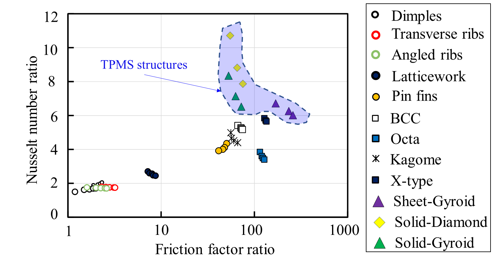
Figure 7
Relative thermal performance for different cooling structures. Dimples [27], Transverse ribs [28], Angled ribs [28], Latticework structures [29], Pin fins [21], BCC [21], Octa lattices [21], Kagome lattices [21], X-type lattices [21], Solid-Diamond structures [31], Sheet-Gyroid structures [31], Solid-Diamond structures [31], Solid-Gyroid structures [31].
2.5. Other Aapplications
InThe order to improve heat and mass transfer in TPMS-based structures are being examined as spacers in the membrane distillation, the TPMS-based structures are being investigated as spacers to enhance heat and mass transfer [32][33]. It was found that compared to commercial spacers, the TPMS-based spacers increaseenhanced the overall film heat transfer coefficient by up to 60%60% compared to the commercial spacers.
The larger surface area is essential for larger chemical reactions in catalytic supports -ports, fuel cells, and battery applications. Abu Al-Rub and Al-Ketan [34] [34] proposed using TPMS-based structures as catalytic substrates. Al-Ketan et al. [35] exanalyzmined the flow characteristicproperties of the solid- and sheet-TPMS-based substrates and revealefound that the CLP topology showed a much lower-based substrate exhibited a well-reduced pressure drop, while the sheet-Gyroid structure causexhibited the highest pressure lossvalue.
FoDiffer organic PCMs (Phase Change Materials), various ent metallic TPMS-based architectstructures have been employed to improve used as thermal conductivity. It was found that in terms of heat transfer performance, enhancers for organic PCMs (Phase Change Materials). It was found that the PCM embedded with the sheet-Primitive structure outprovided superiority in terms of heat transfer performedance over the PCM-alone cases [36], as presented in Figure 8. Also, Quereshi et al. [37] reported that the sheet-TPMS structures showed enhan ced heat transfer performance by increasing the average heat transfer coefficient and minimizedreducing the melting PCM timetime of the PCM. Fan et al. [38] observed that the battery temperature was significantly improved by inteintegrating the TPMS structure into a PCM-based battery thermal management system (BTMS). The averag achieved significant improvement in reducing the battery temperature was found to be around 40% lower with the addition of . They further combined water as a working fluid for the PCM/TPMS-based BTMS, eliminating and it was found that the average battery temperature was lower than without a cooling water system by about 40%, which eliminated the thermal saturation of the PCM.
![Comparisons of heat flux and liquid fraction for PCM only and Primitive PCM, adapted from [36].](/media/item_content/202212/figure8-63a67fdd19d3d.png)
Figure 8 Comparisons of heat flux and liquid fraction for PCM only and Primitive PCM, adapted from [36].
Recently, Qureshi et al. [39] reported for the first time thatutilization of TPMS modelarchitectures impregnated with PCM have been used for high heat flux cooling applications for the first time. It was observed that under conditions of high heat flux, the the TPMS-based structures significantly reducedmitigated temperature. Moreover, they also found that because copper has good thermal conductivity, switching under high heat flux conditions. Moreover, a change in heat sink material from aluminum powder (AlSi10Mg) to use as a heat sink resulting in better temperature controlcopper showed better temperature mitigation because of the favorable thermal conductivity.
Baobaid et al. [40] compared the solid-Diamond, solid-Gyroid and sheet-Gyroid structures for three boundary conditions. in the free convection. It was found that It was found that the sheet-Gyroid structure achieved superior thermal performance when opening the top and bottom surfaces of the enclosure, the sheet-Gyroid structure provided better thermal performance. Still, its surface temperature was the highest when opening the sides and top surfaces. They summarized that the fsheet-Gyroid structure with a larger surface area was opposed by the flow resistance withininside the complex structure of the sheet-Gyroid construction was very high, which significantly reduced, causing a considerable decrease in thermal performance.
3. Effects of TPMS Ddesign Vvariables on Fflow and Heat Theat transfer
3.1. Porosity
The porosity (ε) is defined as the fluid volume divided by the total volume of the chaonnelsidered system. It has been mostly maintainfixed at equivalent values to compare the effects of different TPMS topologies on flow and heat transfer performance. The porosity values can can also be set to the same values infor the uniform or graded TPMS-based structures. Moreover, toin many investigate the flow and heat transfer characteristicsions, the porosity of the specific TPMS topology has been changed in various researchvaried to observe the flow and heat transfer characteristics.
3.1.1. Equivalent porosity
The majMority of studies have examinst research has analyzed the flow, heat, and mass transfer for various TPMS-based structures withunder laminar flow regimes for the uniform porosity in laminar flow systemof different TPMS structures. For heat exchanger applications, Cheng et al. [41][42] inovestigated that we TPMS-based structures' morphology [41][42]. In the numerical model, th increasing Reynolds numbers,e cold gas flowed in the TPMS-based structures and cooled the pore and solid matrix interface, which was heated with the constant heat flux. It was reported that the interstitial Nusselt number values for the sheet-Primitive structure marginally increased. Tincreased slightly at higher Reynolds numbers. In contrast, the values for the sheet-Diamond, sheet-IWP, and sheet-Gyroid structures, on the other hand, increased in a quasilinear fashion becausmanner since the complex curvatures broke the boundary layer. The sheet-IWP model achieved the highest heat transfer, while the sheet-Primitive model caused the lowest values. However, it can be expected that the sheet-Diamond structures could provide the highest values when the Reynolds number is larger than 200.
TKaur and Singh [43] compared the averaged heat transfer coefficients of the sheet-Gyroid and sheet-Primitive structures withat an equivalent porosity for heat sink applications were compared by Kaur and Singh [43]here the coolant flow passes the TPMS-based structure that was heated by a constant heat flux. The simulation results showed that compared to the sheet-PrimitiveGyroid structure, the sheet-Gyroid structure ha provided a higher heat transfer. Even though than the sheet-GyroidPrimitive structure resulted in a high-pressure loss in the channel, it . Moreover, the sheet-Gyroid structure outperformed better than ththe sheet-Primitive structure under particularat specific pumping power conditions. Sreedhar et a, even though it caused a high-pressure loss in the channel. [33] Sreported thathar et al. [33] compared differento other solid-based TPMS architectures, the sostructures, i.e., Gyroid, Primitive, IWP, Fischer Koch S, and transverse Schwarz CLP (tCLP), at the Reynolds number of about 20–60. They reported that the solid-Gyroid structure significantly increasconsiderably improved mass transfer and decreasereduced pressure loss. Similar results were also acquired by Thomas et al. [44], which further found that although the tCLP topology had a higher pressure loss thanexhibited a superior overall film heat transfer coefficient to the other TPMS structures, it showed a better overall film heat transfer coefficient.
For but caused the highest pressure loss in turbulhent flow systems, t.
The flow characteristics and heat transfer capabilitieserformance of a cooling channel at a particularfor heat sinks at a specific porosity have also been investigatedtested for turbulent flow regimes. Yinzheng et al. [45] showanalyzed that due to the greater heat dissipation area in e heat transfer performance of the solid-Gyroid, solid-Diamond, and solid-Primitive structures. The results showed that the solid-Diamond structure, it ha presented the bhighest heat transfer performance. T owing to its larger heat dissipation area. In contrast, the solid-Primitive lattice, meanwhile,structure showed the lowest flow resistance in the channel. Al-Ketan et al. [30] compausred the lowest channel flow resistance. Al-Ketan et alheat transfer performances between the solid-Gyroid, solid-Diamond, and sheet-Gyroid structures in a cooling channel heated on 4-side walls at the Reynolds number of about 4000–65,000. [30]It was found that the sheet-Gyroid structure achasieved the highest convective heat transfer coefficient due tobecause of its complex curved wallature. Among these TPMS topologies, Khalil et al. [31] [31] further observed that as the Reynolds number increased, the ssolid-Diamond structure hashowed the best thermal performance as a result ofthe Reynolds number increased owing to reasonably increased pressure loss and significantly improvncreased heat transfer. AIn additionally, the sheet-Gyroid structure presenteshowed the lowest thermal performance in the comparison since it caused the highest-pressure loss.
Accord ing to he system.
Al-Ketan et al. [30],[30] the variation inxplained that the pressure loss in variation in the channel was due to the differentce in pore sizes, as seen, as demonstrated in Figure 9., where Tthe diameter of the maximum sphere (red sphere) that fitspassing through the smallest hole of the TPMS-based structure iwas employed to describe the pore size. It can be observed that the sheet-Gyroid structure h, causing the highest pressure loss, has the smallest pore size, followed by the solid-Diamond and solid-Gyroid structures. Hence, the sheet-Gyroid structure causes the highest pressure loss.
![Figure 9 The maximum sphere, passing through the smallest hole of different TPMS lattices: (a) Sheet-Gyroid structure; (b) Solid-Diamond structure; (c) Solid-Gyroid structure, adapted from [30]](/media/item_content/202212/figure9-63a680b2ae48b.png)
Figure 9 The maximum sphere, fitting the smallest hole of different TPMS lattices: (a) Sheet-Gyroid structure; (b) Solid-Diamond structure; (c) Solid-Gyroid structure, adapted from [30].
The maximum sphere, passing through the smallest hole of different TPMS lattices: (a) Sheet-Gyroid structure; (b) Solid-Diamond structure; (c) Solid-Gyroid structure, adapted from [30].
For improving tThe cooling performance, theeffects of grading of the porosity of the TPMS-based structures hasave also been investigated in a number of research. The graded TPMS structure has the same overall porosity as a uniform examined in several studies for enhancing the thermal performance of cooling channels. Graded TPMS structure butis the gradually changes l increase or decrease of the TPMS porosity along the lchannel’s length, width, or height of the channel, which remains the same overall porosity as the uniform TPMS ones.
Qureshi et al. [46] showed that infor terms of conductive and convective heat transfer capabilitihe sheet-Primitive, sheet-Gyroid, and sheet-IWP structures, the gradually increased porosity along the flow direction outperformed the unequivalent uniform and gradually decreased porosity models for different sheet-TPMS structurin terms of conductive and convective heat transfer performances. Moreover, Al-Ketan et al. [30] [30] reported that under turbulent flow regimes, the he graded-solid Diamond structure with porosity variedying from 80.0-–82.5% along the flow direction reunder turbulent flow regimes reduced the pressure loss by roughlyabout 27.6%, while only reducing the overall heat transfer coefficient by decreased by only 15.7%.
Figure 10 shows the velocity vector for uniform and graded diamond-solid structures, investigated by Al-Ketan et al. [30] [30]. As seen the Figure 10a, for the uniform structure, the velocity increases gradually due to the fluid expansion. In the case with negative grading porosity in Figure 10b, the velocity entering the high porosity structure is lower than the corresponding uniform one. This reduction is attributed to the small structure that lesser disturbs the incoming fluid. However, a higher velocity can be observed as the structure is larger downstream. The velocity distribution in this channel is non-uniform as compared to the others. For the case with a positive grading structure in Figure 10c, the velocity increases significantly when the fluid enters the low porosity structure. The velocity magnitude remains similar throughout the channel, indicating better uniformity distribution of the flow.
![Velocity vectors of the uniform and graded diamond-solid structures at Re = 65,326, studied by Al-Ketan et al. [30]](/media/item_content/202212/figure10-63a6810e4e8ee.png)
Figure 10 Velocity vectors of the uniform and graded diamond-solid structures at Re = 65,326, studied by Al-Ketan et al. [30].[30]
AltThough the graded TPMS structures showed were conceived with reasonable heat transfer reductions, they offer higher cooling channel but provide a better thermal performance. Also, t of cooling channels. The graded TPMS-based structures resulted in lighter cooling channels by usingimprove thermal performance and show less material duringconsumption in additive manufacture. However, due to other crucial factors like mechanical strength, hydraulic performance, etc.ing, rendering lightweight cooling channels. However, the graded TPMS-based structures might not be superior to the better than the corresponding uniform ones for some functionsparticular functions due to other important considerations, e.g., mechanical strength, hydraulic performance, etc. [47].
3.1.2. Varying the porosity
The overall contact area is significantly impacted by the porosity variation for a TPMS-basedspecific TPMS structure, which influences considerably affects the overall contact area, changing the flow, heat, and mass transfer. Sreedhar et al. [33] varied the porosity Tof the solid-Gyroid model with greater porosity, according to Sreedhar et al. [33], wstructure in the range of 72–90%. It was reported that the solid-Gyroid model with lasrger observed toporosity significantly enhanceimproved mass transfer and reducelowered pressure loss. However, different investigations found that the porosity of the sheet-TPMS structures had an inverse relationship withseveral studies observed that the convective heat transfer coefficient and friction factor [48][49]inversely varies with the porosity of the sheet-TPMS structures [48][49].
Qureshi et al. [46] found that the convrective and conductive heat transfer were significantly improved in a lower porduction in porosity for the sheet-Primitive, sheet-Gyroid, and sheet-IWP structures. Similarly, Cheng et al. [41] rep considerably enhanced cornducted that the interstitialive and convective heat transfer coefficient . Similarly, Cheng et al. [41] reducported athat as the porosity increased for the sheet-IWP, sheet-Diamond, and sheet-Gyroid structures becaus, the interstitial convective heat transfer coefficient decreased since the velocity declinedropped in the channel at the highlarger porosity. However, due to the larger the convective heat transfer area at the higher porosity values in coefficient for the sheet-Primitive structure, the convective increased at the higher porosity values due to the larger heat transfer coefficient increased, as illustratedarea, as shown in Figure 11.
![Effect of porosity on convective heat transfer coefficient for different TPMS structures at Re = 40, adapted from [41].](/media/item_content/202212/figure11-63a681a50d4f8.png)
Figure 11 Effect of porosity on convective heat transfer coefficient for different TPMS structures at Re = 40, adapted from [41].
3.2. Wall Tthickness
TConcerning additive manufacturing for cooling channels, the relative wall thickness (t) of vadifferiousent TPMS topologies has been defined in order to exploreset to investigate the effects on the flow and heat transfer performance. It should be noted that due to topology differences, the values of porosity (ε), pore size (dpore), and surface area at c = 0 (ATPMS) are chvangried for each TPMS topologysurface at a homogenous wall thickness and unit cell size [50], as shown in Figure 12. At It cthe same wall thickness of t = 0.1 mm and bunit cell size of L = 2.0 mm, the porobserved that tsity, pore size, and surface area of TPMS varied significantly in different TPMS topologies. The sheet-Diamond structure has the largest surface area andwith the same pore size as the sheet-Gyroid structure, whereasile the sheet-Primitive structure has the lowest surface area andeast area with the largest pore size.
![Variations in porosity, pore size, and the surface of TPMS at c = 0 at the wall thickness of t = 0.1 mm and unit cell size of L = 2.0 mm for a unit cell of sheet-based TPMS structures (The correlations for the porosity, pore size and surface area are provided by Poltue et al. [50]): (a) Sheet-Gyroid; (b) Sheet-Primitive; (c) Sheet-Diamond; (d) Sheet-IWP structures](/media/item_content/202212/figure12-63a68227bde40.png)
Figure 12
Variations in porosity, pore size, and the surface of TPMS at
c
= 0 at
the wall thickness of
t
= 0.1 mm and unit cell size of
L
= 2.0 mm for a unit cell of sheet-based TPMS structures (The correlations for the porosity, pore size and surface area are provided by Poltue et al. [50]): (a) Sheet-Gyroid; (b) Sheet-Primitive; (c) Sheet-Diamond; (d) Sheet-IWP structures.
In the laminar flow systrem, accgime 15, Femmer et al. [51] reporteding to Femmer et al. that at the same thickness of 0.4 [51]mm, the heat exchanger with the sheet-Diamond structure achieved a outhigher heat transfer performed tance for inherent pressure loss compared to the sheet-Gyroid, sheet-IWP, and sheet-Primitive structures in terms of heat transfer performance for inherent pressure loss. Similar findings . Similar results were reported by Passos [48], in who ich the best thermal performance was found thatin the sheet-Diamond structure ha. Genç et al. [49] observed theat best thermal performance. Genç et al.at the lowest thickness of 0.16 [49]mm, noted that he friction factors of the sheet-Diamond structure producgenerated the highest pressure loss compared to the sheet-Gyroid and sheet-Primitive structures. Additionally, for all TPMS designsMoreover, the friction factor reduced asdecreased with increasing the Reynolds number increasedfor all TPMS geometries.
Iyer et al. [52] reported that the lowest values of the Nusselt numbers were found in the sheetheet-Primitive structure, as shown in caused the lowest Nusselt number Figure 13values. MeanwhileIn contrast, the sheet-Diamond structure exhibitehad the best heat transfer performance, followed by the C(I2-Y**)., As shownas plotted in Figure 13a. For the friction factor, the sheet-Neovius structure caused the highest values, followed b, y the sheet-FRD structure, while the other TPMS structures provided a comparable pressure loss within the Reynolds numbers rangevarying between 0-300, whereas the sheet-Neovius structure caused the highest–300, as illustrated in values, followed Figure 13by. the sheet-FRD structure. It was aThey also reported that the presdictions of the pressure losses are lower than Femmer et al. [51] and Kaur and Singh [43] [43] because of smaller frictional pressure loss from the semi-infinite curved wall of the TPMS structures has been setatures in their simulations.
![Comparisons of the Nusselt number and friction factor of different TPMS topologies for the same infinitesimally thin walls (The correlations are provided by Iyer et al. [52]): (a) Averaged Nusselt numbers; (b) Friction factors.](/media/item_content/202212/figure13-63a6829a37568.png)
Figure 13
Comparisons of the Nusselt number and friction factor of different TPMS topologies for the same infinitesimally thin walls (The correlations are provided by Iyer et al. [52]): (a) Averaged Nusselt numbers; (b) Friction factors.
AFor higher Reynolds numbers, Li et al. [53] compared the flow and heat transfer characteristicording to Li et al.s of the sheet-Gyroid and sheet-Diamond structures for a homogenous wall thickness of 0.7 [53],mm. It was reported that the thermal performance of the sheet-Gyroid structure was suphigherior to than the sheet-Diamond model at high Reynolds numbers. The substantial in. The different results from the previous investigations [48][51] can be attrease in ibuted to the large turbulent kinetic energy (TKE) generation due to the fluid mixing at high Reynolds numbers in the sheet-Gyroid structure is the reason that makes high heat transfer, which shows the different results from the earlier investigations. This intensive fluid mixing was preferable for heat transfer [48][51].
Attarzadenh et al. [54] ianvcestigated tment.
The ediffects of varyingrent thicknesses of the sheet-Diamond structure on the flow and heat transfer performance for a heat sink cooling channel under laminar flow were studied by Attarzadeh et al. [54]. They claimreported that while the larger wall thickness increased theprovided a higher convective heat transfer coefficient, it imped; however, a considerably large wall thickness blocked the flow field, lowerdecreasing the thermal performance of the cooling channels.. As shown in Figure 14, illustrates thea continual declineous decay of reverse flow in the channel was observed, which lowersreduced the pressure loss as thewhen decreasing wall thickness is decreased. D. The lowest thickness showed the best thermal performance due to low-pressure loss and a moderate increase in heat transfer, the lowest thickness demonstrates the best thermal performance in their simulations in the channel.
![Demonstrations of reverse flow regions for small thickness (left) and large thickness (right) of the sheet-Diamond structure at a specific Reynolds number [54].](/media/item_content/202212/figure14-63a682fa40c4e.png)
Figure 14
Demonstrations of reverse flow regions for small thickness (left) and large thickness (right) of the sheet-Diamond structure at a specific Reynolds number [54].
Later, to find the optimal configurations, Attarzadeh et al. [55] investigatudied a multi-objective optimization approachworkflow based on a Genetic Algorithm for laminar flow to reveal the optimal configurations. The sheet-Gyroid structure was chosen to investigateselected to study the TPMS design variables. It was shownobserved that betterincreasing wall thickness improved thermal performance resulted from thicker walls. Additionally, they claime. They also suggested that the pore size and the wall thickness exhibited the greateof the TPMS structure were the most Pareto -sensitivity duringe in the optimization. It should be noted thatmarked that the results did not conflict with the previous findings by Attarzadeh et al. [54] since the TPMS topologies and unit cell sizes usemployed in the study are different, the results did not disagree with the earlier findings by Attarzadeh et al. [54]presenting different results between them.
3.3. Unit Cell Scell size
The effects of unit cell size for the TPMS topologies affectingon the flow and heat transfer performances are rarely discussefound in the literature. Acc Zimmer et al. [56] investigated the pressure loss in thrding to Zimmer et al.ee different unit cell sizes of the sheet-Diamond structure at 8 mm, 4 mm, and 2 mm They reported that [56], the largest unit cell sizes cgenerausted the low-pressure loss in the system, whereasile the smallest one significantconsiderably increased pressure loss, especialparticularly at higher velocities. Similar to thisly, Al-Ketan et al. [35] discfovereund that the sheeat the same wall thickness of 0.6 mm, the sheet-Gyroid and sheet-Primitive structures with the smaller unit cell size caused higher pressure loss because of more complicatedex geometries and lower porosities. Attarzadeh et al. [55] investigated three different cell sizes of the shown ineet-Gyroid structure in a cooling Figure 15,channel. They reported ithat can be inferrdecreasing the unit cell size improved the thermal performance of the heat exchanger. It can be deduced that a smaller unit cell size resulted in caused higher pressure loss because ofdue to the lower porosity but increasedachieved higher heat transfer due to the larger specific surface areas (Sv). Later, according to Attarzadeh et al. [55], reducis showng the unit cell size enhancedin the thermal performance of the heat exchangerFigure 15.
![The sheet-Gyroid structures with different unit cell sizes at the same thickness of 0.6 mm, adapted from [35].](/media/item_content/202212/figure15-63a6836d5b959.png)
Figure 15 The sheet-Gyroid structures with different unit cell sizes at the same thickness of 0.6 mm, adapted from [35].
4. Conclusion
RecenExt experimental and numerical investigationensive studies have been extensively analyzreviewed to highlightshow the effects on flow and heat transfer enhancement in cooling channels with Ttriply Pperiodic Mminimal Ssurfaces (TPMS). The effects of wall thickness, porosity and unit cell size from recent experimental and numerical studies. The extensive results include the effects of porosity on the flow field and heat transfer from, followed by the extensive results. are demonstrated and discussed. The following are tffects of wall thickness and unit cell size. The main conclusions are drawn as follows:
- With the same porosity, as the Reynolds numbers increase, more complicated TPMS topologies, such as the Diamond and Gyroid models, achieve high heat transfer but result in substantial pressure loss. Their tortuous topologies and greater surface areas, which significantly alter the flow characteristics, are the main reason for this increase. The graded TPMS-based structure that increases the porosity along the flow direction presents higher thermal performance than the uniform one due to lower pressure loss while maintaining high heat transfer in the channel.
- The porosity in the majority of the sheet-TPMS structures has an inverse relationship to the convective heat transfer coefficient and the friction factor. Except for the sheet-Primitive structure, a high-speed velocity area along the flow direction interacts with the heating walls in the lower porosity model.
- With the same wall thickness, different TPMS structures show a difference in the porosity and surface area, which changes flow and heat transfer characteristics in the channel. Under laminar flow, the Diamond structure provides the best thermal performance. In contrast, for turbulent flow systems, the Gyroid obtains better heat transfer because of increased turbulent kinetic energy. However, due to the TPMS topologies and unit cell sizes, the wall thickness variation affects the flow field and heat transfer enhancement differently. However, most of the research found that the larger wall thickness exhibits larger convective heat transfer and pressure loss.
- With the same porosity, more complex TPMS topologies, e.g., Diamond and Gyroid models, achieve high heat transfer as the Reynolds numbers increase but cause high-pressure loss. This increase is due to their tortuosity topologies and larger surface areas, considerably changing the flow characteristics. For heat sink applications, the graded TPMS-based structure along the flow direction provides better thermal performance than the uniform one due to decreased pressure loss with maintaining high heat transfer in the channel.
- The convective heat transfer coefficient and friction factor inversely change with the porosity for most of the sheet-TPMS structures, except for the Primitive model, because a large high-speed velocity area occurs in the lower porosity model along the flow direction, significantly interacting with the heating walls.
- Different TPMS topologies with the same wall thickness have different porosities and surface areas, leading to flow and heat transfer variation. Under laminar flow, the Diamond heat exchanger shows the best thermal performance, while for turbulent flow regimes, the Gyroid heat transfer obtains better because of increased turbulent kinetic energy. The larger wall thickness shows higher convective heat transfer and pressure loss; however, owing to the TPMS topologies and unit cell sizes, the wall thickness variation affect the flow field and heat transfer enhancement differently.