EV cTharging requires either single-phase or three-phase charging stations that have unis paper proposes a design for the Bidirectionnal or bidirectional power flow capabilities. Moreover, EV charger can make use of tal electric vehicle charger which is capable of doing both the Grid to Vehicle and Vehicle to Grid power transfer, and the interaction powertrain equipment to achieve high will be made through an automatic smart energy management system(EMS). A simple power density and weight reduction in order to save space in the vehicle while increasing efficiency.electronics topology is used. The user can adjust the output of this charger by using the control signal provided by the controller. The simulation result obtained shows that it has an interaction between the charger and an Energy Management System(EMS) in a residence
1. Specifications
G
Abstract
The enormous numberally speaking, an electric vehicle charging station should comply with the following specifications and deliver a number of other functions, particularly durability, efficiency, and performance:
-
Implement a power factor correction: absorb a sinusoidal current free of harmonics with a power factor equal to 1.
-
Bidirectional power electronics topology that allow participating to the energy storage on the grid in order to implement a vehicle-to-grid or vehicle-to-home concept.
-
Using the traction inverter in the EV charging power electronics.
-
No additional filtering inductance by using traction motor windings.
-
Possibility of balancing battery elementary cells by implementing a part of battery management system functions.
-
Contactless power transfer.
2. Power Electronics Solutions
To of automobiles across the world has caused a significant increase in emissions of greenhouse gases, which pose a grave and mounting threat to modern life by escalating global warming and polluting air quality. These adverse effects of climate change have motivated the automotive sector to reform and have pushed mtheet these EV c drive towards the transformation to fully electric. Charging stations requirements, several power electronics solutions have been proposed and implemented by car manufacturers and energy providers. These solutions are briefly presented and discussed in the following subsectime has been identified as one of the key barriers in large-scale applications of Electric Vehicles (EVs). In addition, various challenges are associated with the formulation of a safe charging scheme, which is concerned with appropriate charging converter architecture, with the aim of ensuring a safe charging protocol within a range of 5–10 min. This paper provides a systematic review of thharging technologies and their impacts on battery systems, including charger converter design and associated limitations. The readers may referFurthermore, the knowledge gap and research directions are provided with regard to the following paper for more details on power elechallenges associated with the charger converter architecture design at the systems level.
1. Introduction
Rec
ent
ronics configurationsly, Electric Vehicles (EVs) have gained popularity over [1].
2.1. Unidirectional Battery Charger
Unitradi
rectional
chargers have a diode bridge rectifier (DBR)fossil fuel-based automobiles, which cause environmental pollution by releasing greenhouse gas emissions (GHG) [1,2,3,4]. aEVs
sociated with a filter stage and a not only curtail carbon emissions but also reduce the burden of fossil fuel dependency [5]. DC/DCKey converter, as shown in Figure 1.bottlenecks in enabling larger EV adoption include Tthe
DBR can be either single-phase (Figure 1)high cost due to batteries, range anxiety due to
r three-phase to increas reduced battery capacity and speed, high charging time, and lack of sufficient charging infrastructures [6,7,8]. To mee
t the cha
rging power. Moreover, a high frequency isolation transformer is used to ensure isolation during EVllenge of time, it is possible to develop highly efficient, reliable, and compact EVs by enabling game-changing battery charging technologies with the aim of reducing charging
time and enhancing battery capacity [9,10,11].
ThIt is
converter topology does not have the abilexpected that EV penetration by 2030 will be approximately 30% of all vehicles sold that will be either electric-powered or hybrid [12]. Chi
na, t
y to use EV battery as energy resource and then inject power to the utility grid. However, ihe US, and Europe are, so far, the biggest EV exporters worldwide, and the sales volume of EVs increased at a rate of 94% between 2011 and 2015. The Li-ion battery itself accounts for 40% of the total production cost of EVs. Prices of Li-ion batteries were reduced from $600 per kWh in 2012 to $250 per KWh in 2017 [13]. The recent
ta
llows providing ancillary services, mainly voltage regularget is set to push the price drop further to $100 per KWh by 2024. EVs have become a hot topic of research since 1990, therefore it is important to understand the development trend and technological barriers.
Charging t
ime i
on, by supplying or absorbing reactive power from ths the key bottleneck, particularly for Battery Electric Vehicles (BEVs), where it ranges from 2 to 6 h [14]. Thre
e main grid without EV battery disclassifications have been made by the U.S. Department of Energy based on charging
EV power capacity.
Figure 1. Unidirectional battery charger for EVs.
U The first in
iclud
irectional baes charging EVs at less than 5 kW [9,15,16], t
he second covers t
ery chargers offer a simple and easy-to-controlhe fast-charging power range between 5 and 50 kW, and the last one denotes a charging power range greater than 50 kW [17]. The firs
olution to manage EV fleet and meet the requirements for safe, reliable, and cost-compt two are referred to as on-board chargers that are integrated into the vehicle, while the third one is referred to as an off-board charger, which is basically equivalent to a fuel station [18]. The re
ducti
tive EVon in the size of the off-board charg
ing solution. However, with the increasing penetration of EV in the transportation sectorer is the future focus of research. Still, the on-board charger can charge the battery on a domestic load. However, the mileage capacity is restricted to 240–300 Wh/mi [19]. Thus, i
f t
is intenhe vehicle is needed to
play a key role in tmake an extra trip urgently outside the daily drive, it would require fast-charging solutions.
EV ch
arging syste
main grid regulation (mainms can be categorized into three groups based on the power levels, as shown in Table 1. Usually,
the chargers frequency and voltage regulation)with a power level below 3.3 kW (1-phase) are termed slow chargers or Level 1 chargers with 120Vac outlet, which can
not be totally ensured using unidirectional EV be integrated in-to the vehicle power train (on-board charge
rs. Consequently, there is a need for bidirectional power flow topologies that allow EVs to act as a distributed energy storage on the power systemr) or can be installed as a convenience outlet at home (wall-charging outlet). The charging time for Level 1 charger is higher which is 4–11 h for 1.4 kW (for PHEV battery of 5–15 kWh capacity) and 11–36 h for 1.9 kW (for EV battery of 16–50 kWh capacity). Level 2 chargers can charge EV batteries with a power of up to 22 kW for both 1-phase and 3-phase with 240Vac (US standard) and 400Vac (EU standard) [2][3][20].
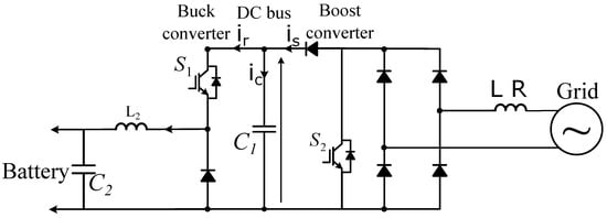
2.2. Bidirectional Battery Charger
B Si
dmi
rectional EVlar to Level 1 chargers
are composed of two stages, which are a single-phase or three-phase active front end (AFE) followed, they can either be part of the vehicle or part of the dedicated Electric Vehicle Supply Equipment (EVSE) outside the vehicle. Three types of charging time scenarios are available for Level-2 charger such as 1–4 h for 4 kW with
a bidirectional DC/DC converter, as depicted in Figure 2PHEV battery capacity of 5–15 kWh, 2–6 h for 8 kW with EV battery capacity of 16–30 kWh and 2–3 h for 19.
2 AFE is a bidirectiokW with EV capacity of 3–50 kWh [20]. On
al AC/DC converter that allow regulating the DC bus voltage and controlling quasi-sinusoidal grid currents, while ensuring a unity power factor (current phase angle control) or exchanging reactive power with the power grid. The second stage athe other hand, Level-3 chargers have power levels up to 200 kW and they are always outside the vehicle as a part of EVSE. Level-3 charger has both ac and dc power facilities with voltage outlets of (208–240) Vac and (200–600) Vdc. It is mostly applicable in commercial area analogous to a filling station. It is termed as fast charging prototype due to its less charging time which is 0.4–1 h for 50 kW prototype and 0.2–0.5 h for greater than 90 kW prototype. The battery capacity of the dedicated EVs ranges from 20–50 kWh [20]. All
three types o
ws controlling thef chargers convert AC grid voltage to suitable DC voltage to charg
ing current of e the battery. The
DC/DC converter can be either isolpower levels determine how fast the battery will be fully charged from a specified state-of-charge (SOC) level [21].
Table 1. Charging characteristics and required infrastructure of some manufactured PHEVs and EVs (data collected from [14,15,16]).
The cha
rging characte
d or non-isolated circuit configurations as discussedristics and required infrastructure of some of the commercially available Plug-in electric vehicles (PEVs) and EVs are shown in
[1]Table 1.
TMost of the vehi
s converters topology offers a bidirectional power exchange with the main grid to sucles have either a Level 1 or Level 2 charger as a part of their vehicle power train (on-board chargers). However, Level 3 fast charging is the quickest option to charge any EV battery if the required connector is available in the vehicle.
A U.S. Dep
artment of Energy report
in 2008 [22] point
he
grid during congestion periods and behave as additional energy storage during off-peak periods.
Figure 2. Bidirectional battery charger for EVs.
Bd out that charging location is critical for building future EV mobility and classified the locations for EV charging into three groups: (i) Residential garage charging (Level 1 and Level 2), (iidi) aparectionaltment complex charging has several advantages compared to unidirectional(Level 1 and Level 2), and (iii) commercial facility charging (Level 2 and Level 3). For both the home and apartment scenarios, it is assumed that a majority of the charging. During EV charging operation, it has been shown that the use of will be performed at night. For commercial facilities, it is assumed that charging is primarily performed during normal business hours.
Several bidire
ctionalview papers on charging
can increase the benefits bytechnologies of EVs can be found in the literature based on a number of factors [23,24]. In [25], a
t least 25% comp
arehensive re
d to standard unidirectionalview of EV charging station infrastructure, standards of charging
through the vehicle-to-grid (V2G) principle. In bidirectionalcables, cords, and connectors, the impact of semiconductors devices used in converters on charger performance and cost, and the integration of a charging
, the use of the battery capacity of EVs can also contribute to ancillary services, such as maintai system with the microgrid for better energy management systems have been analyzed. The technologies related to EVs, EV charging systems, and optimization strategies to obtain the available output have been represented in another review [26]. An
overvi
ng frequency and voltage at the nominal levels and controlling congestion risksew of the recent EV market, standards related to charging, grid integration and safety, charging infrastructure, and effects of EV penetration are discussed in [24].
IAn
deed, this distributed overview of the diverse kinds of EVs that are commercially available and associated with energy s
ystem allows can provide/absorb activetorage systems (ESS), as well as a detailed review of public and residential power
to maintain nominal grid frequency (global parameter) and supply/absorboutlets, EV charging cords, and charging stands based on various power levels, was discussed in [27]. The rne
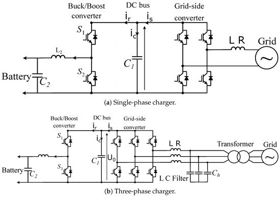
active power to regulate voltage level (local parameter). 2.3. Integrated On-Board EV Charger
ACgative impact of EV charging on the utility grid and the safety code associated with EV charging
syst
ypically needs an on-boardems has also been analyzed. A converter is an integral part of the EV charging system [28]. In [29], a AC/DCreview powerof converter
. Quite architectures, inter
estingly, the motor and the motor drive inverter, whichnational standards, and EV charger manufacturers was analyzed. The architecture of the convert
s the DC power from the battery into AC power for the motor, can also be used as the on-board chaer topologies and the reliability associated with these topologies are considered to be important factors to evaluate the effectiveness of these converter topologies, which were not considered in the aforementioned studies.
Differ
ge
r for the batterynt factors have to be [4]. Icon
side
ed, the existing devicred to design the converter topologies of
the drivetrain are reconfigured with minimum additional EV chargers, such as the efficiency, power factor, isolation, harmonic contents, filter, and switching components
to[30,31,32,33], allow
recharging. This eliminates the need for a separate AC/DC power hich have been highlighted in this paper for both DC-DC and AC-DC converter
for the on-board charger. Since the drivetrs. The reliability of electronic components associated with EV converter technology ensures the reliable performance of the entire system [34,35]. Relia
bili
n ty assessment of the power
conelectronics converter
is usually high power (greater than 100 kW), this also means from manufacturer, seller, and customer standpoints is crucial to verify the reliable operation of the EVs in all environmental conditions [36,37]. Adapt
hat
the EV can reach quite high ion of safe and reliable charging
rates (greater than 22 kW). The challenge is to design the motor methods ensures a long lifetime and better performance of EV batteries by limiting the temperature [38]. The d
rieve
and its control to provide the dual functionality of EV lopment of the fast-charging converter accelerates the revolution toward sustainable transportation through EVs [39,40]. Therefore, different charging
wmethods and ch
en stationary and EV propulsion when in motionarging strategies are important factors in evaluating the total [5][6]. Intpe
grfor
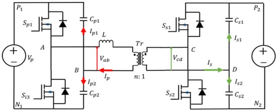
ated on-board EV charger is a bidirectional EV charger that uses a single imance of the EV. EV technologies are facing various challenges such as slow charging, isolation, power loss due to converter
/rectifier for all operation modes structure, power electronic component reliability, and thermal condition of EV
batteries [41].
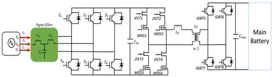
TVehi
s topology allows minimizing thcle to Grid (V2G) is not only a promising solution to cope with a large number of
power electronic devices since the same power switches are used both for EVEVs considering all the aspects of charging and discharging EVs but also a possible way to boost economic growth [42,43]. tClear
action/propulsion, braking, and battery recharging. This way the cost, size, and weight of EV charger are considerably reduced. A topology of such power conversion system is ly, the need to develop reliable and fast chargers is not only important to remove the range barrier, but also to improve the robustness of the EV in the energy transfer context. Therefore, the specific goal of this review is to provide
d in Figure 3 i a detailed overview of the current developmen
t which the sameof the charging converter
is used for supplyarchitecture and converter reliability, highlighting the
motor and rechallenges and potential solutions related to EV charging
.
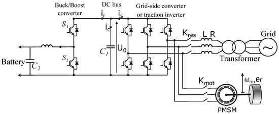
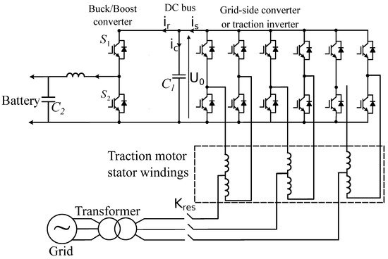
The EVreview battery. In Figure 4,started by collecting the
latest jo
n-board charger configuration uses the traction inurnal papers from major databases such as Scopus and the Web of Science with keywords including EV Charging, EV Charger Converter
as well as the motor windings. The motor windings of each phase are split into two equivalent parts and then reconnected in reverse to cancel the torque in battery, EV charger/converter reliability, Thermal challenges in EV charging, and Vehicle to Grid. One hundred and forty papers were selected for this review with particular focus given to the key topics related to EV converter topology and reliability and EV charging. This paper first reviews and presents available converter topologies of both AC-DC and DC-DC converters for charg
e mode. Motor winding acts as an inductor filter so that the line currents are smooth sinusoidal currents with low THDing architectures. An overview of the reliability analysis of EVs and EV converters with diverse reliability assessment methods to ensure reliable converter performance and future trends related to EV converter topologies have been discussed. Various EV charging methods and strategies are presented, highlighting the [7]. Achargin
g excellent examplechallenges, thermal challenges of th
is implementation is the Renault ZOE EV, whiche battery, and V2G as potential solutions. Finally, insights into the fundamental charging protocol and guidelines for new research directions are provide
d.
2. EV Converter Topology
The EV charger us
ually 43 kW on-board AC fast fast charging. The Renault has claimed to use a junction box that helps in modifying the operation of the motor and motor drive components to be used as ancreates a non-linear load in the power system, which causes problems such as weak power factor and excessive total harmonic distortion in the network. A well-designed battery charger aims not only to safely charge the battery pack with high efficiency but also to meet international standards such as IEEE 1547 [44]. Therefo
n-boardre, all EV charger
.
Figure 3. Bidirectional battery charger for EVs using traction inverter.
Figure 4. Bidirectional battery charger for EVs using traction inverter and motor windings.
Ths need a powe
r main issue with these integrated on-board EV chargers is the produced motor torque due to the current flowfactor correction (PFC) stage, an isolation stage, and filtering components. Several power electronics converter topologies are proposed in the literature to achieve these. The 6.6 kW prototype proposed by Lee et al. [45] used a sing
le-phase iPMW rectifier in the
motor windings. One solution to control the torque is to use a mechanical brake during battery first stage and a full bridge resonant converter in the second stage. The rated efficiency in both charging and discharging
. Other solutions that depend on the motor type can be mentioned: I modes was approximately 93%, but the power density was poor (less than 1 kW/L). The prototype used Silicon (Si) super-junction MOSFETs in the
case of AC motor with wound rotor, cutting off the excitation cancels the magnetic power stage. A three-phase 10 kW prototype based on a three-phase active rectifier and a dual active bridge converter proposed by Zeljkovic et al. [46] (Infi
ne
ld of the rotor. Therefore, the interaction between the stator andon) showed approximately 91% efficiency for the worst battery charging condition (195 V), with the topology presented in Figure 1. The proto
r magnetic fields is canceled and the zero torque condition is maintained during charging. However, evetype mostly used Si devices except for the high-voltage section of the dual active bridge (DAB) where Silicon Carbide (SiC) JFETs (Junction Field-Effect Transistors) were used.
Figure 1. Three-phase on-board charger topology based on active rectifier and single DAB.
2.1. Development Trend of DC-DC Converter
In
if[28], the
DAB excitation is switched off, reluctant torque may occur, causing the machine to vibrate or even rotate. In the case of a permanent magnet synchronous motor, since it has no starting torquetopology with the series-resonant converter (SRC) topology and two-stage series-resonant converter topology were compared for the DC-DC stage of the charger. It was found that the two-stage SRC was more efficient compared to the DAB topology. However, the
stator windings of the three-phase machine can be connected to the grid without the risk of rotor rotation.analysis was shown for a 12 V battery charger (auxiliary charger) rather than the main battery charger of the vehicle. SRC and two-stage SRC topologies are shown in However,Figure 2 vibra
tionsnd mayFigure 3, res
till occurpectively [47].
Figure 2. SRC DC-DC converter topology.
Figure 3. Two-stage SRC topology.
A Mmo
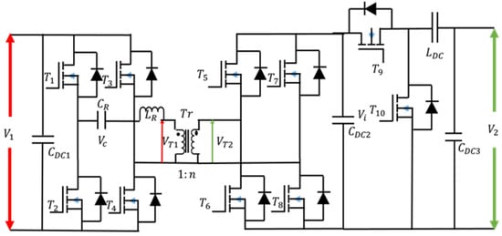
reover, the integrated on-boarddified DAB converter topology for an EV charger
s present other was proposed in [48], draw
backs as follows:
-
Need for a specially designed electrical machine;
-
Difficulty in accessing the neutral point of motor windings;
-
Reduced reliability due to the use of mechanical contactors.
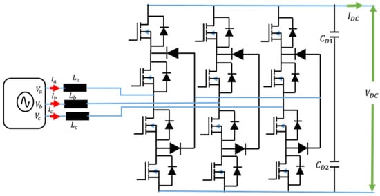
2.4. Bidirectional Battery Charger Using Modular Multilevel Converters
Thishich uses a turned L-C-L network type of embedded chargers use modular multilevel improve the efficiency of the converters (MMC), which are more attr by reducing the reactive currents in the active than two-level converters and neutral point clampbridges. Although the topology reduces the capacitor requirements of traditional DAB topology, the additional L-C-L filter could increase the overall volume of the converters. MMC is
Severa
nl advanced
voltage source converter that has competitive advantamodulation strategies have been proposed to reduce the reactive current in the active bridges such as
output power high quality, highpulse-width modula
rity, simple scalabilitytion (PWM) with phase shift [49,50,51,
52] fa
ult tolerant capabilitynd triangular and trapezoidal modulation [53,
54]. These a
nd low voltage and current rating demand for the dvanced modulation schemes also extend the Zero-Voltage Switching (ZVS) range and increase the low-power
switchesefficiency of the DAB [8][9]topology.
Reactive In recent years, the incorporcurrents can also be reduced by combining the phase-shift modulation
of wideband gap semiconductors (SiC and Gan) are investigatedwith equal PWM in corresponding bridge switches [55]. A tco
implement the MMC application withmposite modulation scheme was proposed in [56] f
uor
ther advan
tages of high-voltage and high-power operations, low ced independent PWM control of individual switching devices, as well as phase-shift, which improves the low-power
losses, high eefficiency
, improved reliability, and of the topology significantly. This is due to the reduced
module size and cooling system [10][11]. Mroot mean square (RMS) current in each switching device. However, the control algorithm is complex and needs to change the modulatilevel cascaded H-bridge convon strategy at different load conditions.
The
r aut
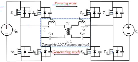
er ihors in [57,58] propos
ed the
best suited for batteryCLLC-based SRC topology for EV charging applications
[12][13].
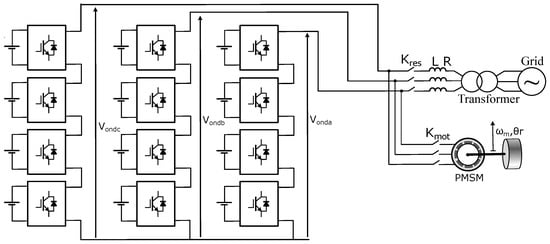
CHo
nverter topology using an MMC at battery cells level to achieve both the traction inverter and on-board battery charger is shown in Figure 5. Iwever, it is clear from their research that the CLLC resonant network design in the SRC converter is much more complicated than the DAB converter design. Furthermore, the voltage gain is very sensitive to various parameters, such as the secondary transformer voltage, load condition, inductan
ce motor mode, power flows from the batteriesof the inductors, and capacitance of the capacitors in the CLLC network. Compared to the
motor through the cascaded inverters. Cascaded inverters can also be used as rectifiers in battery DAB topology, the voltage gain equation in CLLC SRC is much more complicated. To design the parameters in CLLC SRC, all the variations in different parameters should be considered. Even for charging mode and discharging mode
[14][15]. Ioperat
i
s possible to use the motor windings as an inductor, but it is more appropriaons of the EV charger, the topology might require different CLLC parameters to optimize the performance, which significantly complicates the design procedure.
Anothe to use small external inductorsr critical issue with CLLC SRC is that the control complexity is greatly increased when compared with the DAB topology.
Bidirectional battery charger using multilevel modular converters.
2.5. Contactless Power Transfer-Based EV Charger
I2 represenductive charging is the best alternative to conductive s a comparison of various topologies utilized in the DC-DC stage of EV converter topologies for different types of EV chargers.
The du
eal to the many advantages that this technactive half-bridge (DAHB) converter is another promising DC-DC topology
offers. Infor EV fast chargers, which is presented in Figure 4 fac[59]. Alt
,hough this
charging mode has the following advantages: accessitopology has a smaller number of semiconductor switches than the DAB topology, maintaining the closed-loop control stability
, standardized charging, ease of exchanging of inform is very challenging in this topology due to the low-frequency resonance issues. The ZVS range with traditional phase-shift modulation
with the vehicleis very limited as well. An advanced asymmetrical [16], modula
tion
d safety for the user since there strategy is needed to resolve the stability issues and extend the ZVS range.
Table 2. Comparisons of various topologies for DC-DC stages.
Figure 4. DAHB converter topology.
2.2. Development Trend of AC-DC Converter
Although ithree-phas
no electre diode rectifier [20] (uni
direc
al contact tional topology) and 2-level active PWM rectifier [46] a
ndre the
heavy cables are eliminated. This can considerablytwo most popular topologies for the AC-DC stage, several other topologies have been found in the literature, which reduce
the weights the filtering requirements at the PFC stage of the
vehicle and, thusEV charger. For example, [62,
63] itpropos
energy consumption. Inductive charging is ed a three-level neutral-point clamped (NPC) phase-leg-based
on wireless power transfer principle [17][18], aAC-DC converter topology, which is pres
de
picnted in
Figure 65.
InBecause of the th
is configuration, the grid AC voltage is rectified using an AC/DC converter with a power factor correction (PFC) to ensure unity power factor and to adjust three-level operation and the PWM modulation strategy, the topology can reduce the input filter size. Although the voltage rating of each semiconductor device is reduced, the number of semiconductor devices is doubled compared to the two-level active rectifie
d output voltage (which is usually around 400 V)r, which can reduce the power density of chargers greater than 10 kW.
Figure 5. Three-level NPC boost AC-DC converter topology.
A
th
igh frequency inverter is fed by the DC output voltage, producing aree-level T-NPC PWM boost rectifier-based charger topology was proposed in [64]. squarThe
voltage wave at a frequency of 85 kHz11 kW charger achieved an impressive 95.6% peak [19]. The
hffici
gh-frequency inverter is followed by an impedance matching network (IMN) eliminating the current harmonics produced and compensating for the reactive power due tency and 2.5 kW /liter power density by employing a multi-port design approach and a novel phase-shift PEM modulation strategy. Again, the number of semiconductor devices, three times that of the two-level rectifier, is the main issue in this topology.
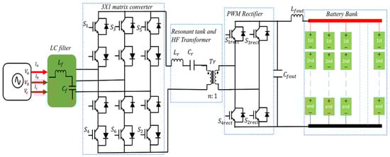
Krishnamo
orth
e ly et al. [65] propose
d a
kage inductance of matrix converter (AC to AC) for EV fast-charging applications, which does not require the tra
nsmitting coil, this block is also knownditional AC/DC/DC structure. The topology is presented in
tFigure 6. The
lifront
erature a-end matrix converter converts the
primary compensation sthree-phase 50/60 Hz AC voltage to single-phase high-frequency AC voltage.
When theThe high-frequency trans
mitter coil is fed with the filtered output former creates the galvanic isolation and the PWM rectifier rectifies the high-frequency AC voltage to DC voltage
of the inverter, it produces a time-varying magnetic field that can be directed towards the receiver coil using ferrite cores allowing wireless power transfer fromsuitable for the battery. This topology ensures single-stage power conversion and removes the DC link capacitor at the output of the conventional AC-DC stage. Therefore, matrix converters usually achieve higher power density when compared to traditional two-stage solutions [66,67].
Figure 6. Matrix converter topology with resonant tank and HF transformer for EV charger.
The auth
eors in [68] gpr
ound assembly to the vehicle assembly. The time-varying magnetic field induces an AC voltage in the receiver coil at the same frequency as primary coil voltage. This voltage is applied to a secondary compensation stage (IMN) and thenoposed an advanced modulation strategy to compensate for the reactive power drawn by the input filter, which reduces the input current distortion and ensures very low total harmonic distortion (THD) for the input current. The controller achieves good dynamic performance in both the charging and discharging modes of the EV battery. However, the matrix converter has twice the number of semiconductor devices compared to the two-level PWM rectifie
d. The rectifier canr, which could reduce the power density of the charger. Table 3 breprese
a controlled rectifier or diode-based rectifiernts a comparison of various topologies discussed in this paper for the AC-DC stage of EV converter topologies for different [20][21].types of InEV bidichargers.
Table 3. Comparisons of various topologies for the AC-DC stages.
3. EV Converter Reliability
Ever
y elect
ionalronic system
s, a controlled rectifier is required to ensure a bidirectional power flow to implement the V2G concept is developed with individual parts or components. Therefore, if any single part fails then it may affect the entire system. From the manufacturing point of view, it is important to ensure [22][23][24]. Fhi
ngh-qual
ly, a buck-boost DC/DC converter is used to control the current delivered to the battery.
Figure 6. Contactless power transfer for EV charging.
3. Summary on EV Charging Stations Technical Requirements
EVity products are delivered to the customers. They should also ensure that the product will perform consistently under various operating conditions. The key chadr
ging modes varies according to several criteria related to efficiency, duriving factors for reliability issues are the massive adoption of electronic systems and their increasing complexity. In addition, customers are expecting high reliability
, performance, and cost. Several from their desired product. For example, in modern electric drives, power electronics
architectures have been investigated in academia and implemented in industry. With the evolution of the vehicle electrical system and the increase in charging power demand for different levels, new types of AC chargers whose operation is based on converters with associated components together work as a power processor mainly for charging the batteries and delivering power to another auxiliary load. Trends of the power converter are shifting toward becoming small in size, compact, efficient, and power dense. They have been popular in EVs due to their ease of control and flexibility in scaling. However, the poor reliability of these devices is an issue, and they fail frequently; therefore, to ensure the reliability of this product, this important issue needs to be considered [69].
The ext
hreme use of
traction inverter and EV motor windings are emergingfossil fuels in the transport sector has contributed to environmental pollution over the past decades. The automotive industry has introduced a new concept for vehicles by replacing fossil fuels with electricity, as the driving force in electric vehicles (Evs) [70]. Th
eus, Evs
e types of chargers allow to provide high power and have a compact architecture and low cost. Moreover, inductive appear to be the best alternative to traditional vehicles. Hybrid Electric Vehicles (HEVs), Plug-in Hybrid Electric Vehicles (PHEVs), and Battery Electric Vehicles (BEVs) are the three major Evs that exist in the current market. Automotive manufacturers are conducting research on designing and manufacturing Evs, whereas charging s
eems to be tations are increasing to feed the Evs.
Reliability very attractive technology for EV charging stations in the near future, especially forassessment plays an important role in maintaining the operation of Evs’ components, mainly the power electronics converter. Reliability assessment is a critical issue for Evs, and various perspectives of reliability are required to be considered:
- I.
-
The dcustome
stir’s standpoint.-
- II.
-
The manufac
turer’s appstandpoint.-
- III.
-
The sell
icer’s sta
tionsndpoint.
-