Photovoltaic (PV) systems made-up by two-stages of energy conversion are attractive from the operation point view. It is because the MPPT range is extended, due to the voltage decoupling between the PV system and the dc-link. Nevertheless, the additional conversion stage increases the volume, cost and power converter losses. Therefore, in large-scale PV systems formed by series connection of PV modules, most of commercial inverters are based on a single-stage system. The concept of partial power converters (PPC), previously implemented as a step-up stage, has not fully covered all PV applications. In this work, a PPC performing step-down operation is proposed and analyzed for a PV string application. This concept is actually interesting from the industry point of view, since with the new isolation standards of PV modules reaching 1500V, larger strings are currently starting to become popular. Since grid connection remains below 690V, larger strings impose more demanding operation for single-stage central inverters (required to operate at lower modulation indexes and demand higher blocking voltage devices).
- dc-dc converters
- string inverter
- partial power converters
1. Introduction
In large-scale solar PV systems, it is usual to find larger PV strings to reach higher DC voltages, and several strings connected in parallel to increase the power, forming an array. Due to PV voltage isolation limits, traditional string voltages are designed to values under 1000V. However, larger PV strings around 1500V are becoming popular, due to reduction of the combiner boxes, and also for the losses reduction in the dc-side. Since grid connection remains below 690V, larger strings impose more demanding operation for single-stage central inverters. It requires to operate the inverter at lower modulation indexes reducing their efficiency, and it requires higher blocking voltage devices. An alternative, is to change the grid connection step-up transformer, to enable a higher AC voltage operation at the inverter side, but this is not a standard equipment.
On the other hand, adding an additional conversion stage performing buck operation leads to increase the component count, converter's size and conversion losses. This is the motivation to take advantage of the PPC concept, which was initially implemented for PV systems, in order to reduce the power losses in the two-stage configurations. The concept of partial power converters (PPC), previously implemented as a step-up stage, has not been fully covered all PV applications [
[1]
-
[2]
]. Therefore, in this work a PPC performing step-down operation is proposed, analyzed and evaluated with a laboratory experimental test-bench.
2. Step-down Partial power converters for PV systems
Nowadays new PV strings reach 1500V insulation, making larger strings a reality, and increasing the need of buck dc-dc stages to properly connect to grid-voltage levels. Step-down PPCs are oriented to these PV applications, so that traditional large-scale PV applications do not work with two-stage systems due to the high conversion losses. In addition, the MPPT is made with the inverter stage, which is also the responsible for the grid-connection. It reduces the global efficiency of the system, specially under partial shading conditions, so that the convert does not have a wide operation voltage range. Therefore, the use of a Step-down PPC for the dc-stage can be an attractive solution in order to increase the dc-stage conversion system, also increasing the MPPT flexibility, due to the decoupled voltage between the PV and the dc-side. Moreover, some other important benefits come from the reduction of weight and size of the converter, due to the reduced power processed by the dc-stage. The efficiency can be expressed with the following equation:

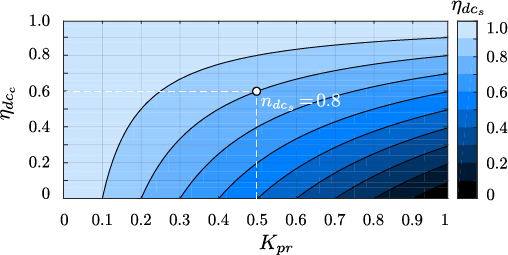
It can be seen that the system efficiency depends on the efficiency of the dc-dc converter used for the PPC configuration, and also the amount of power processed by itself Kpr=Ppc/Ppv. This parameter Kpr is named as partiality ratio and it depends express the amount of power handled by the converter, compared with the total system power.Due to the connection used to create the PPC configurations, the power processed by the converter is reduced. It decreases the conversion losses in the dc-stage, increasing the dc-stage conversion efficiency as can be seen in the following figure:

In the following figure it is possible to see the possible configurations for the Step-down Partial power converter.

Moreover, some circuit topologies are depicted in the following figure:

Moreover, some circuit topologies are depicted in the following figure:
However, the topologies are not limited only to both circuits. It is possible to evaluate different isolated dc-dc topologies as long as the configurations of the PPC are respected.

However, the topologies are not limited only to both circuits. It is possible to evaluate different isolated dc-dc topologies as long as the configurations of the PPC are respected.
3. Experimental results
In order to validate the converter, the following test bench was built:

The obtained results validating the correct operation are presented as follows:
The obtained results validating the correct operation are presented as follows:

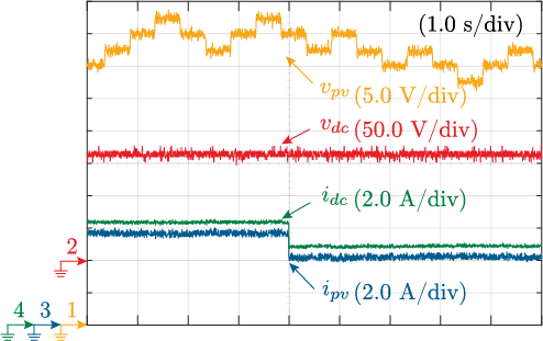
The evaluated parameters are the voltage and current in the system. The voltages are depicted in the upper side of the figure, where the P&O MPPT algorithm presents the classical three levels. Since the voltage at the dc-link vdc is fixed by the inverter, the converter voltage Vpc is the difference between Vpv and Vdc due to the series connection of the PPC. In that case the step-down operation is depicted in the figure, where the output voltage $V_{dc}=167V$ is lower than the input voltage $V_{pv}=230V$. The voltage of the PPC is $V_{pc}=63V$, which is the blocking voltage withstood by the Mosfets, and it is lower than in the case of traditional FPC. It means that the component size is reduced due to the lower voltage rating.
The evaluated parameters are the voltage and current in the system. The voltages are depicted in the upper side of the figure, where the P&O MPPT algorithm presents the classical three levels. Since the voltage at the dc-link vdc is fixed by the inverter, the converter voltage Vpc is the difference between Vpv and Vdc due to the series connection of the PPC. In that case the step-down operation is depicted in the figure, where the output voltage $V_{dc}=167V$ is lower than the input voltage $V_{pv}=230V$. The voltage of the PPC is $V_{pc}=63V$, which is the blocking voltage withstood by the Mosfets, and it is lower than in the case of traditional FPC. It means that the component size is reduced due to the lower voltage rating.
In terms of efficiency the experimental results are presented as follows:
In terms of efficiency the experimental results are presented as follows:

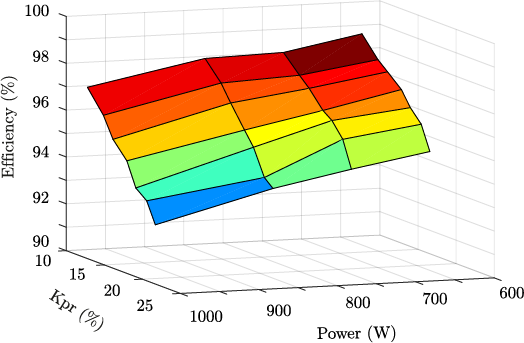
When the converter is operating below a partiality factor K_{pr}<= 25\% of the total power, the dc-stage efficiency varies between 90\% - 99\%, as depicted in the figure. It highlight the benefit using PPCs and the relation between the partiality ratio and the efficiency.
When the converter is operating below a partiality factor K_{pr}<= 25\% of the total power, the dc-stage efficiency varies between 90\% - 99\%, as depicted in the figure. It highlight the benefit using PPCs and the relation between the partiality ratio and the efficiency.
References
- Jaime Zapata; Samir Kouro; Gonzalo Carrasco; Hugues Renaudineau; Step-Up Partial Power DC-DC Converters for Two-Stage PV Systems with Interleaved Current Performance. Energies 2018, 11, 357, 10.3390/en11020357.
- Jaime W. Zapata; Samir Kouro; Gonzalo Carrasco; Hugues Renaudineau; Thierry A. Meynard; Analysis of Partial Power DC-DC Converters for Two-Stage Photovoltaic Systems. IEEE Journal of Emerging and Selected Topics in Power Electronics 2018, 1, 1-1, 10.1109/jestpe.2018.2842638.
