In patients with atrophy of the temporalis muscle or flattened skin flaps (trephined syndrome), CAD/CAM (customized computer-assisted design/manufacturing)-fabricated implants with modified reconstructed curvature is crucial for cranioplasty. For the aforementioned clinical conditions, adequate scalp adaptation is significant for either the maintenance of soft tissue bulk or the prevention of the dead space between the dura and implant. This can thoroughly be achieved by adjusting CAD algorithms for the contouring of skull defects with outwardly elevation or inwardly depression, respectively. We herein demonstrate operative details involving modified contours for the reconstruction of skull defects in CAD Modeling.
- CAD algorithms
- Contour adjustment
- Cranioplasty
1. Introduction
In some circumstances, the CAD algorithms for the contouring of skull defects are likely to be adjusted, either in elevation or depression. In patients with resorption of the autogenous bone grafts or atrophy of the temporalis muscle, newly reconstructed contours should be elevated to compensate for the depressed curvature of soft tissue bulk[1] and deficits of the temporalis muscle.[2]
Thin and flattened skin flaps can be found in the elderly or patients with trephined syndrome[3]. Difficulties in scalp adaptation during cranioplasty surgery are likely to take place in these patients. Difficult scalp adaptation can cause impaired tension-free skin closure and subsequent skin necrosis[4]. Furthermore, a dead space between the scalp and dura can be created if parts of the brain have been removed during the initial decompressive surgery. For the aforementioned conditions, the newly reconstructed contour should be depressed to prevent excessive tension to the scalp, and avoid enlargement of the dead space between the dura and implant.
Thus, smaller or larger CAD/CAM-fabricated implants are likely applied in cranioplasty surgeries under various clinical circumstances. We herein emphasize the significance of the establishment of accurate and symmetrical regular CAD models before adjusting the CAD contours.
2. Demonstration of Adjusting Contours for the Reconstruction of Skull Defects in CAD Modeling
As shown in Figure 1A, we present a schematic planning of the contour reconstruction of a demonstrated case. Firstly, it is necessary to draw the axis of symmetry (the green line). The symmetric contour for the skull defect (line O’) can be addressed by mirror reflecting the curvature of the contralateral skull (line O) via the axis of symmetry. Next, connect the two marginal points of the skull defect (point M and M’). Make a perpendicular bisector through the connection line. Point P represents the intersection of the O' line and the vertical bisector.
Suppose point P is adjusted to elevate by X mm along the perpendicular bisector.
Let the intersection with the perpendicular bisector be point E. An elevated contour is defined as follows:
Definition 1. The arc line connecting point M, M’, and E.
Figure 1B shows the schematic illustration of elevated contour of the skull defect of the demonstrated case. Contours were elevated outward by 4 (intersection with Point E1) and 10 mm (as indicated in Point E2). Reconstructed contours with 4 and 10 mm elevation were achieved by establishing an arc line connecting point M, M’, E1, and point M, M’, E2, respectively. The reconstructed contours of the skull defect with 10 and 4 mm elevation, and a regular contour of axial CT images are shown in Figures 1C,D,E, respectively. The corresponding 3-D models are shown as Figures 1H,I,J. The reconstructed artificial flap with regular and elevated contours is labeled in gray and blue, respectively.
Suppose point P is adjusted to depress by Y mm along the perpendicular bisector.
Let the intersection with the perpendicular bisector be point D. The depressed contour is defined as follows:
Definition 2. The arc line connecting point M, M’, and D.
As indicated in Figure 1B, contours were depressed inward 4 (intersection with Point D1) and 10 mm (as indicated in Point D2). Reconstructed contours with a 4 and 10 mm depression were established by connecting point M, M’, D1, and point M, M’, D2 respectively. The reconstructed contours of the skull defect with a 4 and 10 mm depression of axial CT images are shown as Figure 1F and G respectively. The corresponding 3-D models are shown as Figure 1K,L. The reconstructed artificial flap is labeled in orange.
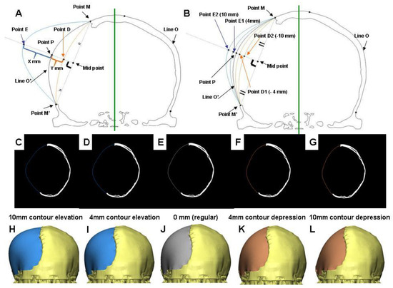
Figure 1. CAD modeling with the contour adjustment of a demonstrated case. (A) Schematic illustration of the definition for contour elevation (Point M-E-M’-connected arc), and depression (Point M-D-M’-connected arc). (B) Schematic illustration of the elevated and depressed contour of the skull defect. Points E1, E2, D1, D2 represent intersection points where contours are 4 and 10 mm outwardly elevated, and inwardly depressed respectively. The reconstructed contour from the skull defect on the CT images: symmetrically filled (E), contour elevation of 4 (D), and 10 mm (C), contour depression 4 (F), and 10 mm (G). (H–L) represented the respective 3-D CAD models.
References
- Woon-Man Kung; Feng-Huei Lin; Sheng-Huang Hsiao; Wen-Ta Chiu; Charng-Cherng Chyau; Shing-Hwa Lu; Betau Hwang; Jia-Hua Lee; Muh-Shi Lin; New Reconstructive Technologies after Decompressive Craniectomy in Traumatic Brain Injury: The Role of Three-Dimensional Titanium Mesh. Journal of Neurotrauma 2012, 29, 2030-2037, 10.1089/neu.2011.2220.
- Martin Scholz; Michael Wehmöller; Jutta Lehmbrock; Kirsten Schmieder; Martin Engelhardt; Albrecht Harders; Harald Eufinger; Reconstruction of the temporal contour for traumatic tissue loss using a CAD/CAM-prefabricated titanium implant-case report. Journal of Cranio-Maxillofacial Surgery 2007, 35, 388-392, 10.1016/j.jcms.2007.06.006.
- Woon-Man Kung; Muh-Shi Lin; A simplified technique for polymethyl methacrylate cranioplasty: Combined cotton stacking and finger fracture method. Brain Injury 2012, 26, 1737-1742, 10.3109/02699052.2012.698361.
- Shuo-Tsung Chen; Cheng-Jen Chang; Wei-Chin Su; Lin-Wan Chang; I-Hsuan Chu; Muh-Shi Lin; 3-D titanium mesh reconstruction of defective skull after frontal craniectomy in traumatic brain injury. Injury 2015, 46, 80-85, 10.1016/j.injury.2014.09.019.