You're using an outdated browser. Please upgrade to a modern browser for the best experience.
Please note this is a comparison between Version 2 by Rita Xu and Version 1 by Mohammad Saleh Meiabadi.
Wind turbines are known to be the most efficient method of green energy production, and wind turbine blades (WTBs) are known as a key component of the wind turbine system, with a major influence on the efficiency of the entire system. Wind turbine blades have a quite manual production process of composite materials, which induces various types of defects in the blade. Blades are susceptible to the damage developed by complex and irregular loading or even catastrophic collapse and are expensive to maintain. Failure or damage to wind turbine blades not only decreases the lifespan, efficiency, and fault diagnosis capability but also increases safety hazards and maintenance costs.
- non-destructive testing (NDT)
- smart inspection
- wind turbine blades (WTBs)
1. Introduction
Wind energy, which has been booming for more than a decade, accounts for a significant percentage of the global energy market. In its latest report for 2021, the Global Wind Energy Council (GWEC) indicates a total capacity of 743 GW of wind turbines installed in the world, of which there were 93 GW of new installations in 2020 alone; among these, 86.9 GW of turbines were installed on land (onshore) and 6.1 GW were installed at sea (offshore) [1]. All these turbines have to operate under various conditions, including salt water, sand particles, insects, lightning, ultraviolet rays, icing, and hot or cold temperatures, depending on the geographical location of the wind-power installations. These factors have an impact on the structure, and the wind turbines must also be regularly inspected to ensure that they are functioning properly and, therefore, producing the estimated energy and meeting the electricity demand. In other words, the inspection can be used to detect the defects in a structure before a failure occurs and prevent stops to energy production.
Wind turbines are increasingly used in northern regions because these regions are characterized by their high wind potential [2]. Therefore, the technology has to adapt to the harsh climatic conditions, including extreme temperatures and icing (the phenomenon of ice accumulation on the blades of wind turbines) which, among other things, complicates the operation and maintenance of turbines in these locations [3,4][3][4]. However, wind farm operators prefer to mitigate the risks rather than avoid these regions, since they contain the greatest wind potential on the planet [4,5][4][5]. When wind turbines are operated in northern regions’ environmental conditions or the mounts, the blades and turbines are also subject to extreme temperatures and icing. Extreme temperatures affect the material used to manufacture the blades, and the blades can become brittle at very low temperatures, crack, or suffer from other damage due to extreme temperatures. Wind-turbine manufacturers are currently able to propose solutions to the severe temperature constraints induced by extreme temperatures in the design, manufacturing, operation, and maintenance (O&M) of wind turbines [6,7][6][7]. The vast majority of problems related to cold weather are, therefore, due to the accumulation of ice on wind turbines [8]. This ice accumulation on the blades increases the stress on the blades, causes significant vibrations that lead to material fatigue, and can also cause damage [9]. Therefore, to ensure sustainable operational conditions in northern climates, the proper choice of blade material is necessary, as well as an appropriate design and manufacturing process, adapted to the harsh winter conditions, and the ability to withstand additional loads due to ice accumulation on the blades. In addition, regular inspection is necessary to ensure the good condition of the blades, detect cracks and failures in time to react and plan repairs, and to ensure the proper functioning of the blades and, consequently, maintain expected energy production.
Canada, as one of the coldest countries in the world, has one of the highest wind-energy potentials in the world. The provinces with the highest wind-energy production are Ontario, Québec, and Alberta. According to CanWEA, in Canada, the 12,239 MW of installed capacity translates into 6409 wind turbines and, therefore, 19,227 blades that require regular inspection and maintenance. Ontario, Quebec, and Alberta share 2515, 1879, and 901 installed wind turbines, respectively; thus, they have 7545, 5637, and 2703 blades, respectively, to inspect and maintain [10]. According to the Government of Quebec [11], the province had 3879 MW of installed wind-power capacity in 2020 (i.e., 1935 turbines integrated and connected to the Hydro-Quebec grid) and is expected to have 3933 MW of wind power by 2022. Therefore, a large number of wind turbines are installed and operated under harsh climatic conditions (i.e., icing and very low temperatures), whose inspection is necessary and of high importance to ensure proper functioning during winter periods (where there is a surplus of production) and to ensure energy production while reducing energy losses.
2. Inspection of Wind Turbine Blades
As wind turbine installations increase, along with operating constraints and climatic conditions that affect the structure and can cause damage, the inspection of the blades and the wind turbine structure becomes an important part of their preventive maintenance. The O&M of wind turbine blades (WTBs) consists of 15–35% of the total costs and the minimization of these costs is very important. The inspection of WTBs is essential to prevent damages that could appear on the blade and diminish its aerodynamic properties, thereby harming the harvesting of wind energy and reducing electricity production. Therefore, keeping the blades in a suitable condition is essential to prolong the lifespan of WTB and maximize performance. It should be noted that an inspection is used to identify the defects in a structure and, in this research, the selected structure is the WTB. If not repaired, these defects can lead to loss of efficiency and, in the worst case, fatal failure [12]. In addition, wind turbines are often installed in remote sites with difficult access (onshore in the mountains or offshore). Moreover, the blades are fixed on the rotor at a height of 100 m or more. WTBs are difficult to access, with risky conditions during inspection that makes it even more complex and costly. In addition, winter weather makes inspection increasingly problematic. Health and safety concerns are also raised when inspecting these wind turbines. Therefore, it is necessary to plan and organize an inspection plan to ensure the ongoing operation and maintenance (O&M) of the turbines in harsh winter conditions. Typically, the inspection involves an employee turning the turbine blades downwards. Another employee climbs to the top of the tower and then rappels down the blade to visually inspect the surface of the blade and possibly take photos of any defects that are encountered. This process must be repeated for each blade and may take from 2 to 4 h depending on the quality of the defects being documented [12]. According to CNESST, three employees (one on the ground, two at altitude) are required for wind-turbine inspections and repairs (i.e., climbing and repairing) and favorable climatic conditions are necessary to climb to a height. Therefore, the use of an automated or semi-automated inspection solution is essential. This could replace a repetitive and dangerous task when executed by humans (manual inspection is performed either in elevation by rope or by platform) and make it better organized and more achievable using digital technologies (camera, laser, etc.), allowing for safe imaging of the structure. In general, the blades are inspected approximately once every five years during the manufacturer’s warranty period, after which they are inspected every two years [13]. When the turbine is operating in a northern environment, additional stresses are added, which can cause damage to the blade. Therefore, it is recommended to inspect the blades more frequently, e.g., annually. The inspection of WTBs is costly, as it must be carried out at height and under favorable climatic conditions (the wind turbine must be shut down during the inspection). Therefore, operators are looking for fast, reliable, and low-cost inspection services that allow for the operator to prioritize the maintenance activities and evaluate the material and human resources, as well as find the most convenient time to repair defects that were identified. This is smart inspection and smart maintenance planning. In this study, vVarious inspection methods that are applicable to the blades of wind turbines in operation will be presented. These methods will be compared based on the following criteria: speed, quality/reliability, and cost. Before presenting these different WTB inspection methods, the methods and materials used to manufacture WTBs will also be presented, followed by the loads applied to the blades and the possible damage.3. Manufacturing, Load Types, Damages, and Standards of Wind Turbine Blade
The wind is harvested through wind turbines, which generate electricity by rotating the blades attached to the rotor, which is attached to the nacelle at the top of the tower, as shown in Figure 1.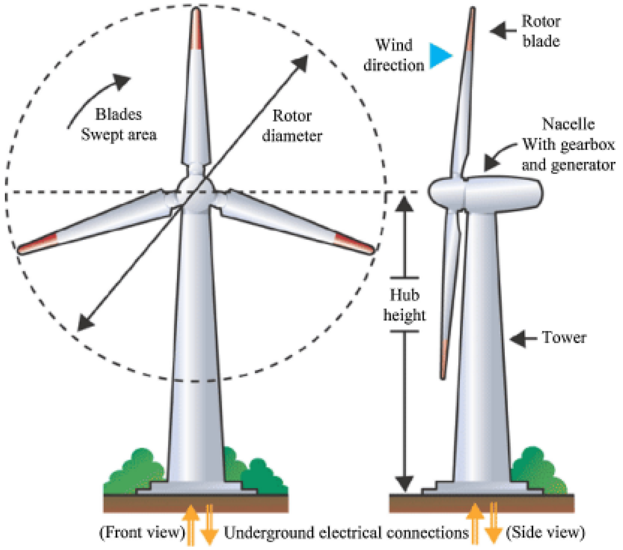
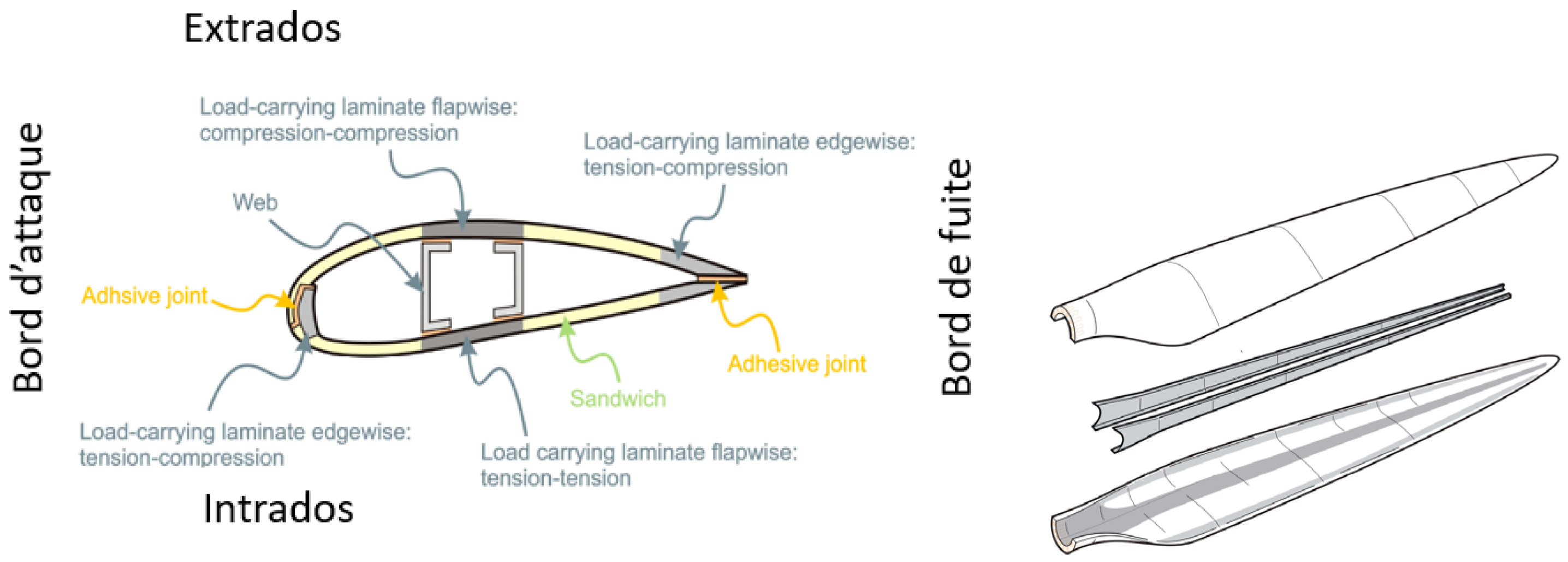
3.1. Manufacturing of Wind Turbine Blades
Wind turbine blades are manufactured with composites using a process that is still very manual, leading to different types of defects. Hence, non-destructive testing is required to provide information on the surface and sub-surface of the blade while demonstrating the ability to inspect the blade from the surface [18]. Early types of WTBs were manufactured by wet hand lay-up technology (Figure 3a). Fiberglass was impregnated with rollers and brushes. After being joined by adhesive, the shells are connected to the stringers. The cloths for the larger blades are sandwiched using the same approach but with a higher plies’ fiber content. As shown in Figure 3b, product quality improved with vacuum infusion and the prepreg approach. The prepreg technology was developed by aerospace productions, using impregnated composite fibers. Resin infusion technology was adopted for large turbine blades by positioning the fibers in a closed mold; then, the resin is pumped into the mold. Heat is also applied for curing as soon as the resin settles on the fibers. This technique can be classified as resin transfer molding and vacuum-assisted transfer molding (Figure 3c) [19].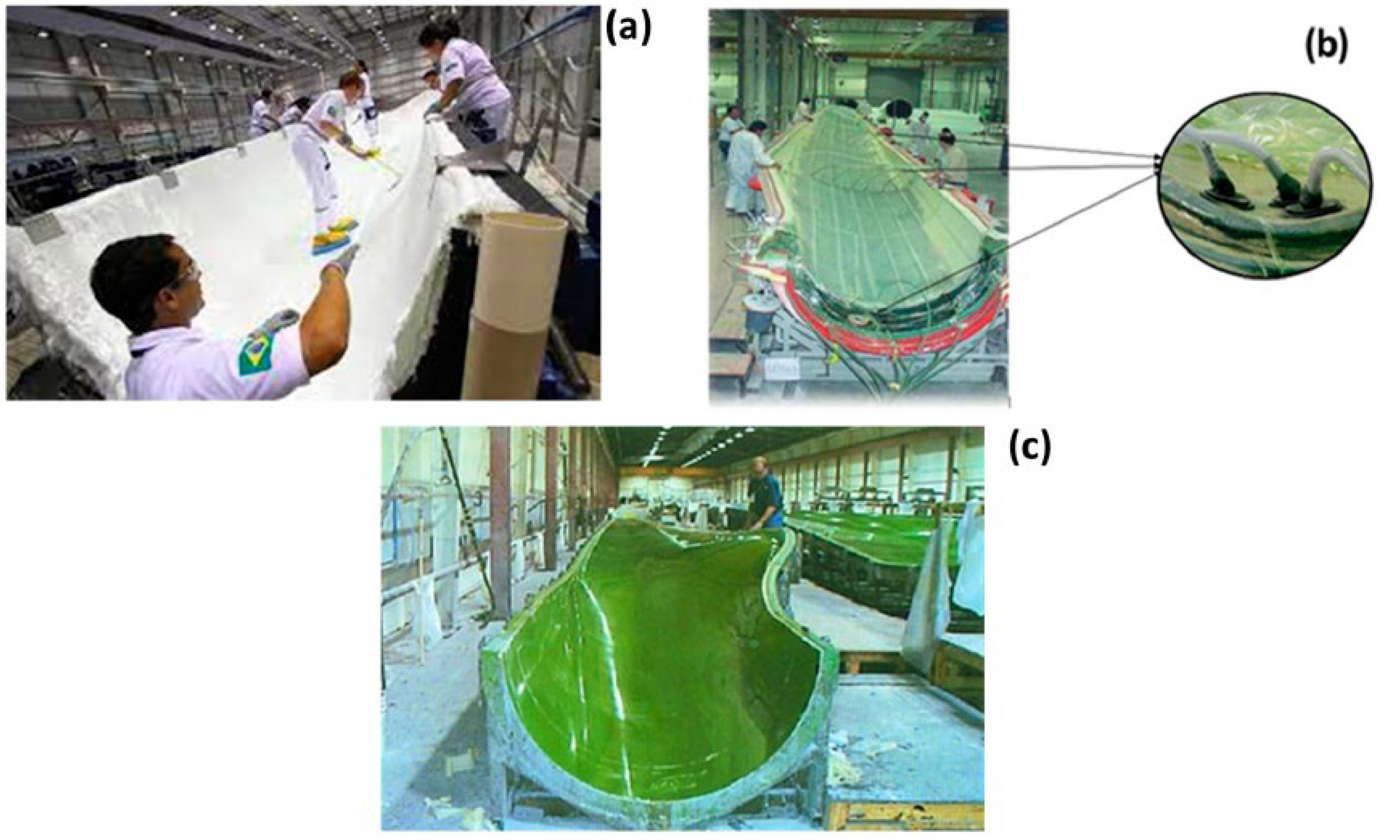
Figure 3. Manufacturing processes of a wind turbine blade (a) hand lay-up, (b) vacuum infusion or prepregging, (c) vacuum-assisted resin transfer molding (VARTM) [19].
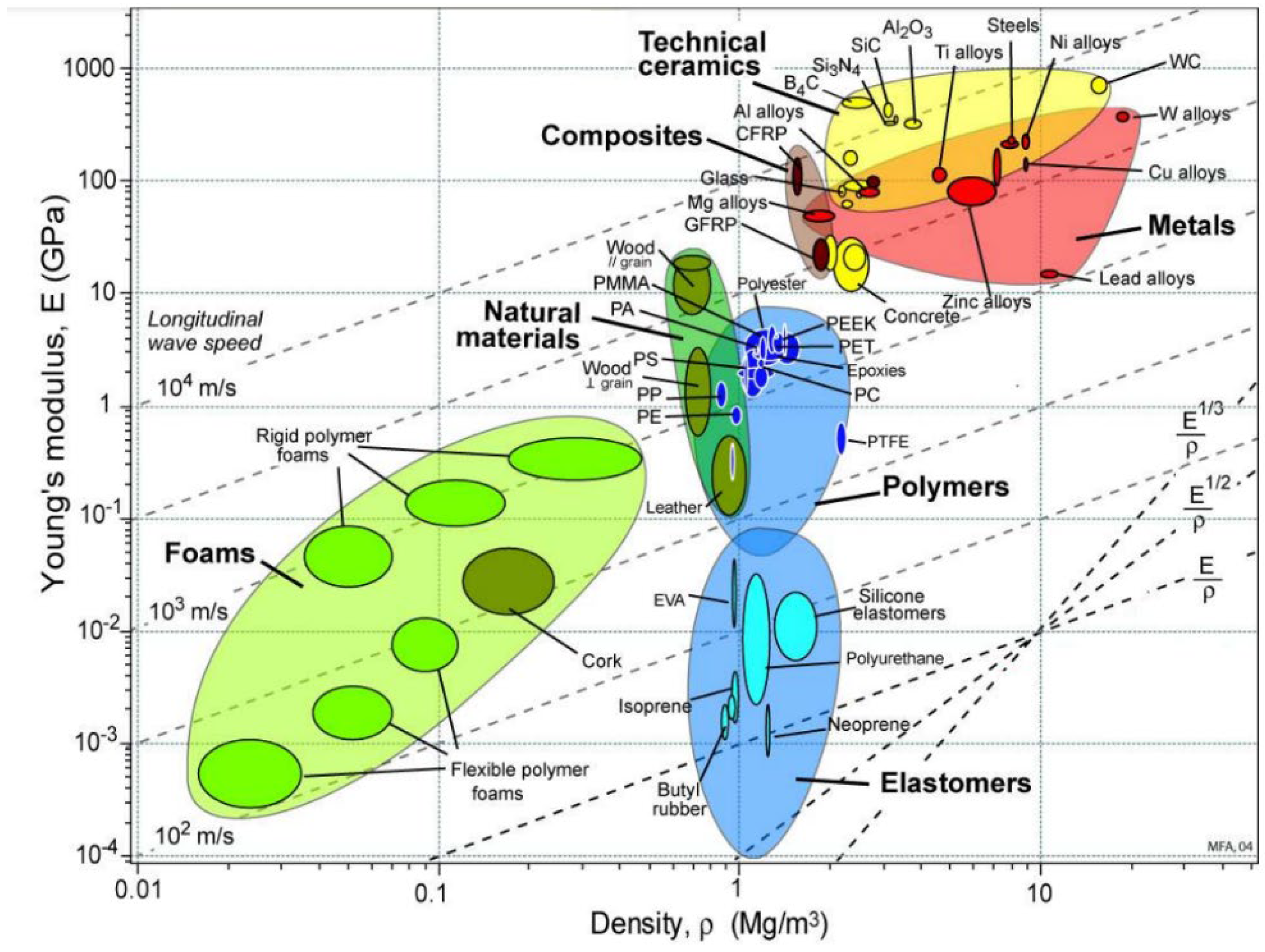
3.2. Damages in Wind Turbine Blades
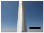
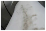
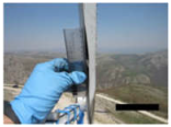
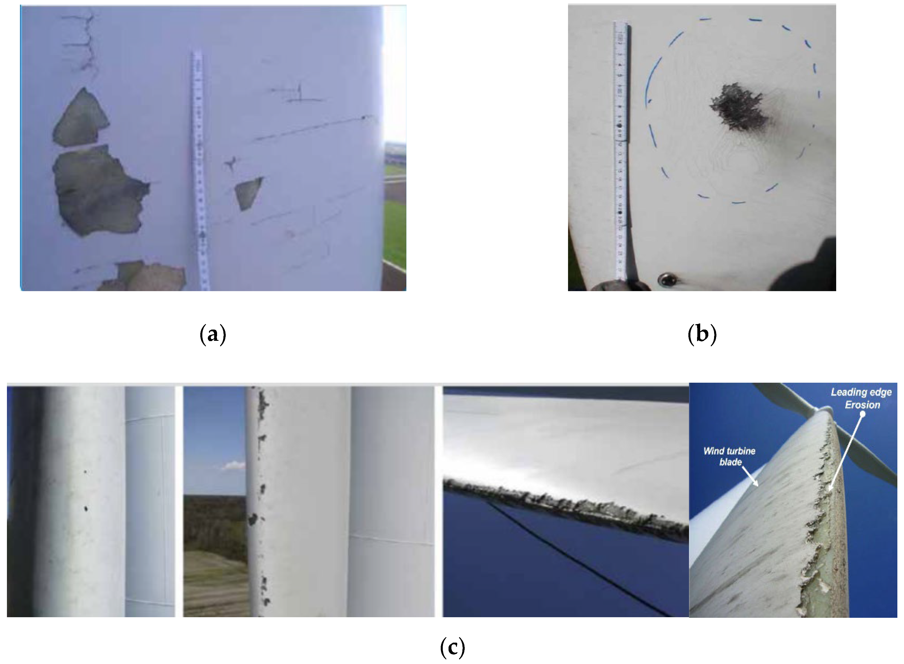
The defects encountered on a wind turbine blade can originate from the design, manufacturing, handling, operation, or repair. A defect might also have been created for multiple other reasons [21,22,23][21][22][23]. Poor design, i.e., underestimation of loads and poor defect characterization, can lead to damage during operation or handling (during transport of the blade). The manufacturing process of WTBs is not very automated and, despite the rigor applied in the quality control, some defects on the blades can escape the intiail inspections in a factory. In this case, a dry fiber or a ratio rich in fiber can lead to local delamination. While handling the blades either during transportation (often over long distances) or during installation by crane, the blades can be subjected to shocks or compressions, causing scratches, and chipping (on the leading or trailing edge). Once in operation, the blade is subjected to multiple potential causes of wear or failure, including leading edge erosion, lightning strikes, frost, particles from agricultural land, ultraviolet radiation, salt air, birds, and insects. Poorly executed repairs can lead to new defects or more severe damage. As explained earlier, a good understanding of the causes of deterioration of composite WTBs is crucial to the life of the blades. This is of great significance, since the blades are subjected to different loadings. Defects in composite materials ending in the deterioration of composites have been extensively studied. Figure 5 presents significant information on the different deterioration mechanisms resulting from the action of loads.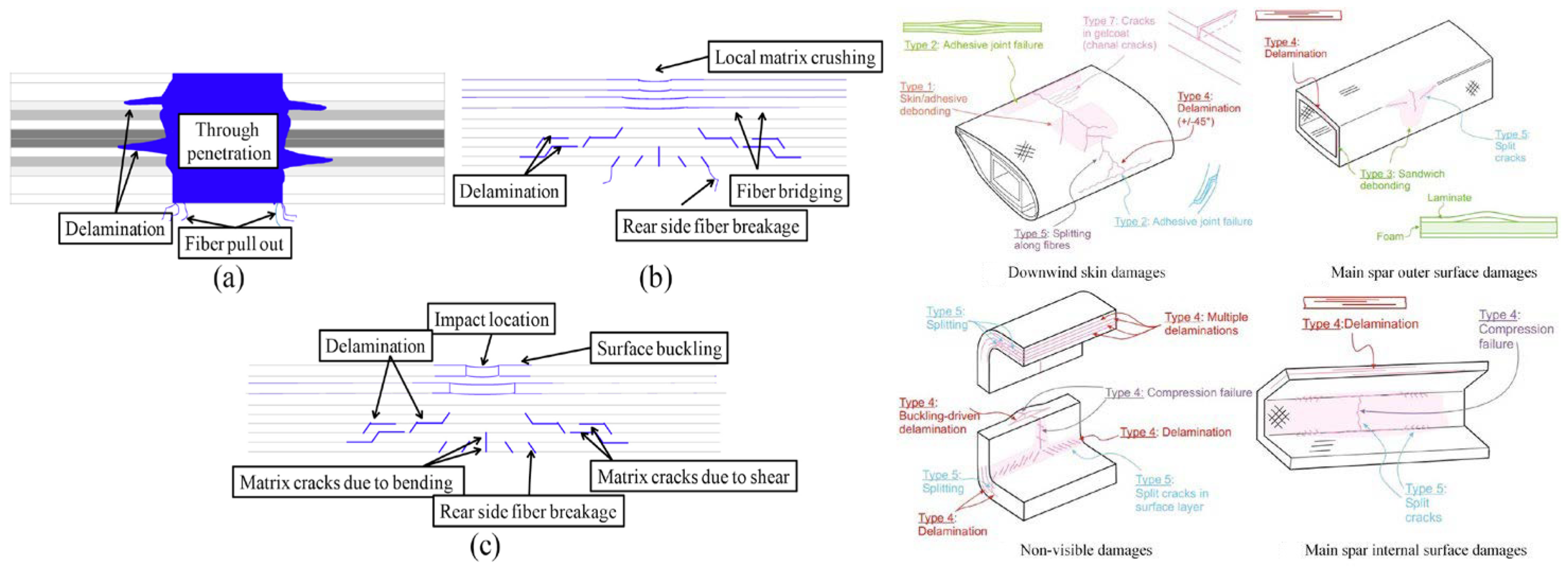
Figure 5. Different types of defects. Deterioration mechanisms caused by impact loading (a) higher, (b) medium and (c) lower [19].
-
Erosion: Wear caused by high-speed collisions between airborne particles and the blade (hailstones, water droplets, sand, insects). Leading edge erosion due to impact fatigue is a serious issue for wind turbine blades, which might be caused by a variety of factors, including collision with rain droplets, hail stones, and other airborne particles. Repeated impacts to the leading edge cause an accumulation of damage and, eventually, cracking of the tip of the material;
-
Dry fiber: An area in the laminate where there is no resin, resulting in a different coloration. The stack of compressed dry laminate experiences the full pressure of the atmosphere—just like the open top of the resin pot, which is about to infuse. The infusion process is such that the atmosphere acts almost like a piston on the resin pot, pushing it down, then through the hose into the low-pressure area inside the bag. This is like pushing down on the plunger of a syringe and injecting the resin into the part just the plunger is the atmospheric pressure;
| Example 1 | Example 2 | Example 3 | Example 4 | Example 5 | |
|---|---|---|---|---|---|
| 1 |  |
 |
 |
 |
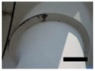 |
| Pinholes in coating at leading edge. | Broken vortex generators. | Scratch in coating. | Erosion or chipped coating. | Grease leakage on blade collar. | |
| 2 | 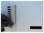 |
 |
 |
 |
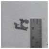 |
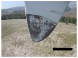
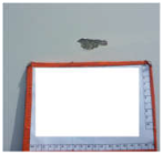
| Small spanwise crack. | Small quantity of vortex generators damaged. | LPS receptor coating damage. | Small area of coating damage. | Small area of coating damage. | |
| 3 | 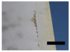 |
 |
 |
 |
 |
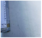
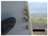
| Several scattered areas with coating damage. | Crack in structure at the leading edge. | Coating damage. | Leading edge erosion. | Coating damage. | |
| 4 | 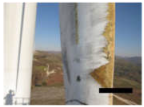 |
 |
 |
 |
|
| Leading edge erosion with large area of exposed fiberglass surfaces. | Coating damage and exposure of the underlying fiberglass. | Trailing edge open over a small length. | Chordwise crack. | ||
| 5 |  |
 |
|||
| Trailing edge open over a significant length. | Long leading edge chordwise crack with spanwise cracking. |
- Delamination: Separation of the laminate layers due to poor infusion at the mill, regarded as one of the most common forms of failure of composite materials. Due to imperfections initiated by the manufacturing process or external factors during the lifetime of composite laminates, i.e., foreign body impact, the phenomenon of delamination can occur;
-
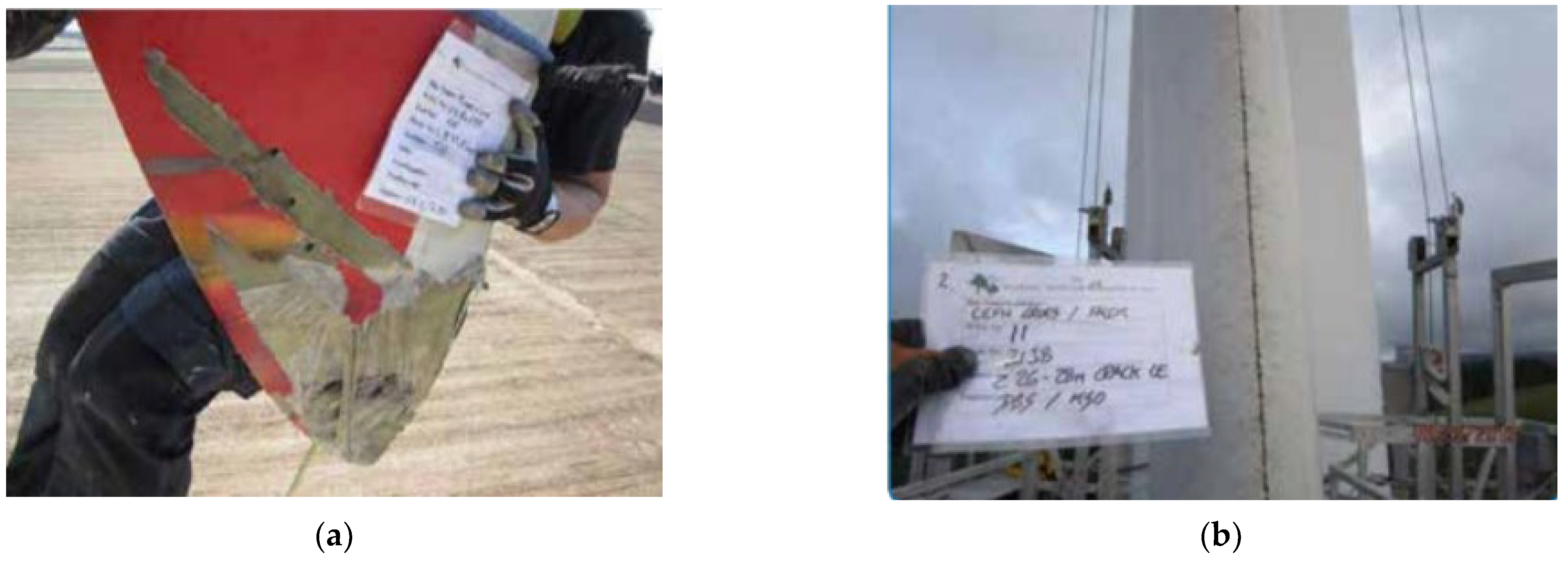
Cracks: Breakage of the laminate or glue joint. Even if it seems harmless, a crack should never be overlooked, since it may be larger in size and may propagate (Figure 7). Mmechanical fasteners (such as clips, screws, etc.) can be used to join composites or mixed materials, but they require additional steps to mold or create features for the fastener. These additional features eventuate in stress concentrations and non-uniform stress distribution, which can result in cracking and failure;
3.4. Standards for Rotor Blades of Wind Turbines
Rotor blades should be designed so that the maintenance of normal operating conditions is ensured. The rotor blades should also reach the expected lifetime with sufficiently high reliability. In addition, the safety of personnel and installations must be ensured and risks of injury to human life must be reduced to a minimum. The rotor blade standards deliver an internationally acceptable level of safety by defining minimum requirements for wind turbine rotor blades (in combination with referenced standards, recommended practices, guidelines, etc.). These standards serve as a design basis for designers, suppliers, manufacturers, purchasers, and regulators to specify requirements for wind turbines subject to certification schemes. The design basis is sufficient for a safe design of the wind turbine rotor blade covering the scope of certification specified as part of the design basis. Design load assumptions that are used as a basis for the design verification of the blade structure should be specified as part of the design documentation. In case of changes in the design loads, a load comparison may be carried out to show that the blade continues to be compliant with the standard requirements. The DNV GL standard, for instance, provides principles and technical requirements for rotor blades for wind turbines both onshore and offshore. This standard is, in principle, applicable to all types of wind turbines and rotor blades, even though many requirements have been formulated specifically for blades made from fiber-reinforced composites for operation on horizontal-axis wind turbines. The DNV GL standard can be applied as part of the technical basis for carrying out DNV-GL-type certification of wind turbines or DNV GL component certification of rotor blades. This standard is applicable to the structural and functional design and manufacturing of rotor blades for wind turbines, including requirements for materials, testing, repair, and operation [33]. For all processes involving polymeric materials, the manufacturing processes to be applied in connection with each material should be reported in a generic process description. For fiber-reinforced composites, these should at least include:-
Type of processing (hand lay-up, infusion, pultrusion, prepreg, or others);
-
Principle of vacuum set-up and level of applied differential pressure;
-
Most relevant processing temperature profiles, at least including application temperature and time, and cure temperature and time (or a definition of a minimum required degree of curing to be achieved by the curing process for each resin system);
-
Target fiber volume content.
-
Type of processing (co-curing, co-bonding, adhesive bonding, or others);
-
Maximum and minimum thickness of adhesive joint;
-
Outer surface quality;
-
Structural integrity of laminates, from the outer as well as the inner surface;Most relevant surface preparation parameters (peel-ply, grinding, protection, open time);
-
Cracking: Grouping of several cracks located at the root of the blade and along the leading edge and surfaces, opposite the spars;
-
Adhesive joints at leading and trailing edge;Microcracks: Cracks (or spalling Figure 6
-
Adhesive joints on the inside (such as shear web joints);and Figure 7) are often thinner than the gelcoat caused by poor infusion at the factory. They are difficult to detect, and their observation depends on the inspector’s perception. In the case of hardening as a consequence of microcracking, the relative displacement of the microcrack faces over loading and unloading cycles causes them to grow;
-
Blistering: Poor adhesion of the gelcoat to the laminate, causing local delamination of the coating. Adhesion failure happens when the adhesive fails to attach firmly to the substrate, which can be perceived as it is separated cleanly from the surface. It should be noted that adhesion occurs in very delicate regions of the surface;
-
Deep cavity: A cavity that reaches one or more layers from the surface;
-
Scratches: Damage, superficial or not, to the surface of the blade;
-
Pitting: Cavities of less than one millimeter, produced by poorly executed or controlled application of the gelcoat;
-
Spalling: Partial (flaking) or complete (exposed laminate) disbondment of the gelcoat.
3.3. Damage and Defect Categorization in Wind Turbine Blades
The assessment of detected wind turbine blade damage usually involves determining its severity and/or criticality. This process helps to categorize observed wind turbine blade damages into common severity categories. The categorization of damage and defects in wind turbine blades is a challenging task that lacks guidance in the form of an industry standard. However, categorization enables decisions on the maintenance actions, execution, and timing of repairs, considering practical and commercial concerns such as season, accessibility, the impact of downtime, and the availability of crews and materials. To assess the damages and defects of different blades, categories 1–5 are presented as potential answers. Categories 1 and 2 are considered for minor damage or defect, categories 3 and 4 for moderate damage or defect, and category 5 for major damage or defect. In some cases where multiple defects are present, lower-category defects may be grouped to form higher-category defects. Further, it may be cost-efficient to monitor several lower-category defects as single, higher-category defects. Recategorization is generally needed for lower category damage and defects [32]. Category 1–3 damage or defects can often be operated with inspections every 6–12 months. Category 3 or 4 damage or defect should be repaired or shut down within 6–12 months, with at least an inspection every 6 months. Category 4 or 5 damage or defect should be repaired or shut down within 1–12 months, with monthly monitoring. Only the most severe damage and defects are considered serious enough to stop the turbine until it can be repaired. Moderate and less serious damage can be monitored once or twice a year with ongoing operation. For lower damage and defect categoriess, growth would need to be 100% or more before the action plan is reconsidered, whereas with damage or defects in categories 4 or 5, any (or a small amount of) growth would be cause for concern and re-evaluation.- Most relevant processing temperature profiles, at least including application temperature and time, and cure temperature and time (or a definition of a minimum required degree of curing to be achieved by the curing process for each resin system).
- Attached items (e.g., lightning protection);
- Lightning events;
- Corrosion and pre-tension of bolts;
-
Mechanisms or installed systems, if applicable.
References
- Global Wind Energy Council. GWEC Global Wind Report 2019; Global Wind Energy Council: Bonn, Germany, 2017.
- Dimitrova, M.; Ibrahim, H.; Feger, Z.; Illinca, A.; Perron, J. Revue et analyse comparative des méthodes de protection contre le givre appliquées aux éoliennes. In Proceedings of the XIVème Colloque International Franco-Québécois en énergie, Baie St-Paul, QC, Canada, 16–20 June 2019.
- Dimitrova, M. Pertes Énergétiques D’une Éolienne à Partir Des Formes de Glace Simulées Numériquement. Master’s Thesis, UQAR, Rimouski, QC, Canada, August 2009.
- Dimitrova, M. Optimisation de la Performance Opérationnelle et de la Maintenance des Éoliennes Exploitées en Milieu Nordique. Ph.D. Thesis, UQAR, Rimouski, QC, Canada, 2022.
- Fakorede, O.; Feger, Z.; Ibrahim, H.; Ilinca, A.; Perron, J.; Masson, C. Ice protection systems for wind turbines in cold climate: Characteristics, comparisons, and analysis. Renew. Sustain. Energy Rev. 2016, 65, 662–675.
- Davis, N.; Zouhair, K.-Y.; Rolv Erlend Bredesen, A.S.; Vindteknikk, K.; Norway Göran, R.; Wickman, H.; Bourgeois, S. Available Technologies for Wind Energy in Cold Climates–Report; IEA Wind Task: Paris, France, 19 October; pp. 38–62.
- Kilpatrick, R. Effect of Cold Climate on Wind Energy Production in Canada (2010–2016); NAtural Resources Canada, CanmetENERGY: Ottawa, ON, Canada, 2017.
- Lacroix, A. Atmospheric Icing Effects on Wind Energy Production in Canada. In Proceedings of the Winterwind 2013, Östersund, Sweden, 12–13 February 2013.
- Laakso, T.; Peltola, E.; Tammelin, B. Wind Turbines in Icing Environment: Improvement of Tools for Siting, Certification and Operation—NEW ICETOOLS; FMI: Helsinki, Finland, 2005; p. 127.
- The Canadian renewable energy guide; McKirdy, A.R. (Ed.) General Store Publishing House: Renfrew, ON, Canada, 1999.
- Wilson, C.; Ontario Ministry of Natural Resources and Forestry, Peterborough, ON, Canada. Personal Communication, 2018.
- André, P.N. Méthodes D’inspection Automatique D’infrastructure Par Robot Mobile, Ets; Ecole Polytechnique: Montreal, QC, Cannada, 2017.
- Fauteux, L.; Jolin, N. Drone solutions for wind turbine inspections; Nergica: Gaspé, QC, Canada, 2018.
- Rehman, S.; Al-Hadhrami, L.M.; Alam, M.M.; Meyer, J.P. Empirical correlation between hub height and local wind shear exponent for different sizes of wind turbines. Sustain. Energy Technol. Assess. 2013, 4, 45–51.
- Yu, D.O.; Kwon, O.J. Predicting wind turbine blade loads and aeroelastic response using a coupled CFD–CSD method. Renew. Energy 2014, 70, 184–196.
- Doroshtnasir, M.; Worzewski, T.; Krankenhagen, R.; Röllig, M. On-site inspection of potential defects in wind turbine rotor blades with thermography. Wind. Energy 2016, 19, 1407–1422.
- Du, Y.; Zhou, S.; Jing, X.; Peng, Y.; Wu, H.; Kwok, N. Damage detection techniques for wind turbine blades: A review. Mech. Syst. Signal Process. 2020, 141, 106445.
- Taheri, H. Utilization of Non-Destructive Testing (NDT) Methods for Composite Material Inspection (Phased Array Ultrasonic). Master’s Thesis, South Dakota State University, Brookings, SD, USA, 2014.
- Olabi, A.G.; Wilberforce, T.; Elsaid, K.; Sayed, E.T.; Salameh, T.; Abdelkareem, M.A.; Baroutaji, A. A review on failure modes of wind turbine components. Energies 2021, 14, 5241.
- Li, X.; Wu, L.; Ma, L.; Yan, X. Effect of temperature on the compressive behavior of carbon fiber composite pyramidal truss cores sandwich panels with reinforced frames. Theor. Appl. Mech. Lett. 2016, 6, 76–80.
- Mishnaevsky, L.; Branner, K.; Petersen, H.N.; Beauson, J.; McGugan, M.; Sørensen, B.F. Materials for wind turbines: An Overview. Materials 2017, 10, 1285.
- Li, D.; Ho, S.C.; Song, G.; Ren, L.; Li, H. A review of damage detection methods for wind turbine blades. Smart Mater. Struct. 2015, 24, 033001.
- Chandrasekhar, K.; Stevanovic, N.; Cross, E.J.; Dervilis, N.; Worden, K. Damage detection in operational wind turbine blades using a new approach based on machine learning. Renew. Energy 2021, 168, 1249–1264.
- Kawakami, H. Lightning Strike Induced Damage Mechanisms of Carbon Fiber Composites; University of Washington: Washington, DC, USA, 2011.
- Sela, N.; Ishai, O. Interlaminar fracture toughness and toughening of laminated composite materials: A review. Composites 1989, 20, 423–435.
- Yashiro, S.; Ogi, K. High-velocity impact damage in CFRP laminates 7. Dynamic Deformation, Damage and Fracture. Comp. Mater. Struct. 2016, 23, 169.
- Bruno, G.; Kachanov, M.; Sevostianov, I.; Shyam, A. Micromechanical modeling of non-linear stress-strain behavior of polycrystalline microcracked materials under tension. Acta Mater. 2019, 164, 50–59.
- Ahmad, F.; Dent, M.; Yunus, N. Shear bond strength of two chemically different denture base polymers to reline materials. J. Prosthodont. Implant. Esthet. Reconstr. Dent. 2009, 18, 596–602.
- Pfaffel, S.; Faulstich, S.; Rohrig, K. Performance and reliability of wind turbines: A review. Energies 2017, 10, 1904.
- Cerbe, B. Damages to Rotor Blades and Their Causes; Chez Wind Turbine Blade Manufacture: Düsseldorf, Allemagne, 2010.
- Slot, H.M.; Gelinck, E.R.M.; Rentrop, C.; Van Der Heide, E. Leading edge erosion of coated wind turbine blades: Review of coating life models. Renew. Energy 2015, 80, 837–848.
- EPRI. A White Paper on Blade Defect and Damage Categorization: Current State of the Industry; ERPI: Palo Alto, CA, USA, 2020.
- Jiang, Z. Installation of offshore wind turbines: A technical review. Renew. Sustain. Energy Rev. 2021, 139, 110576.
More
