Rotor dynamic scattering refers to the phenomenon that a rotating rotor-like component continuously deflects incident radar waves in the observation field to generate dynamic echoes. This scattering feature has obvious dynamic characteristics and periodic characteristics. Factors such as observation angle, radar wave frequency, polarization mode, rotor disc angle and rotor carrier attitude angle are closely related.
The emergence of dynamic scattering has transformed the rotor radar cross-section (RCS) problem from static solution to dynamic analysis. Studying rotor dynamic scattering has great engineering value for designing stealth rotors from the dynamic RCS level.
- helicopter
- rotor
- radar stealth
- radar cross-section
- dynamic electromagnetic scattering
1. Introduction
With the continuous improvement and development of armed helicopters, the research on their stealth characteristics has become more and more in depth. In order to obtain the complex effect of stealth characteristics caused by the high-speed rotation of rotor-like components, a dynamic scattering method (DSM) is presented. Rotation speed, azimuth, elevation angle, pitching angle, and rolling angle are studied and discussed in detail. The results show that the electromagnetic scattering characteristics of the main rotor and tail rotor are dynamic and periodic. This period characteristic is related to the rotation speed and attitude angle of the rotor. The RCS of the helicopter varies greatly at different observation angles and attitude angles, but the dynamic electromagnetic scattering effect caused by the main rotor and tail rotor cannot be ignored. The presented DSM is effective and efficient for studying the dynamic RCS of the rotor-type parts of a helicopter or the whole machine.
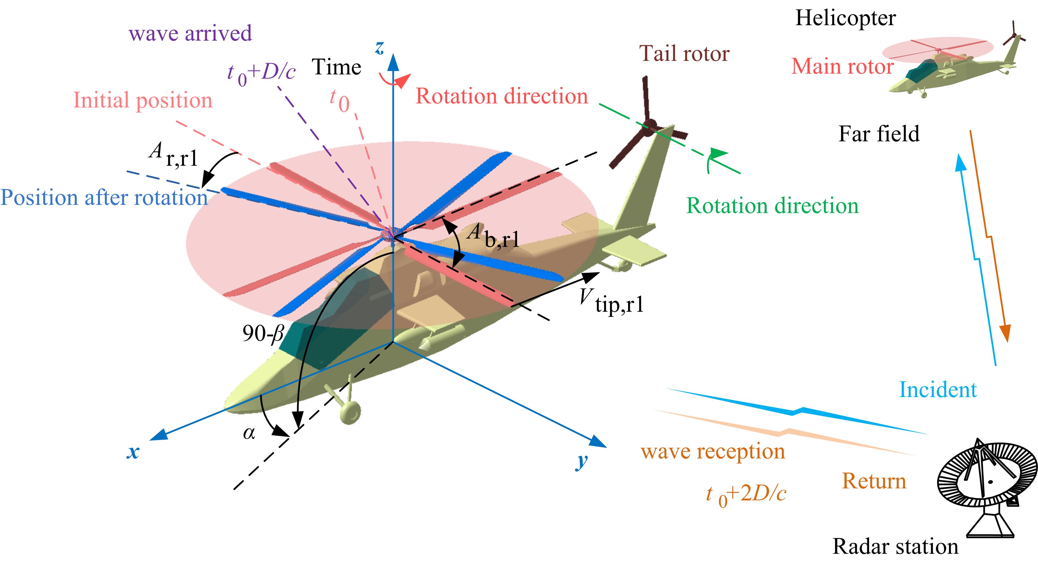
Figure 1. Schematic diagram of the effect of rotor rotation on the helicopter radar cross-section.
Figure 1. Schematic diagram of the effect of rotor rotation on the helicopter radar cross-section.
Basic Information for Authors:
Zeyang Zhou, Postdoctoral fellow, Beijing University of Aeronautics and Astronautics, School of Aeronautical Science and Engineering, Department of Aircraft, under the direction of Professor Jun Huang, research direction aircraft design, aircraft stealth technology, flight mechanics and flight safety.
Jun Huang, Professor, Beijing University of Aeronautics and Astronautics, Aircraft Department, PhD Supervisor. Taught undergraduate courses such as "Introduction to Aerospace", "Structural Optimization Design", "Design Experiments for Micro-Miniature Vehicles", "Introduction to Aircraft Design", as well as "Analysis of Combat Effectiveness of Aviation Weapon Systems", "Overall Integrated Design of Aircraft", "Multiple Aircraft Postgraduate courses such as Discipline Optimization and Aerospace Engineering Practice. The main research directions are overall aircraft design, weaponry combat effectiveness analysis, and weaponry stealth technology.
Definition:
When electroen electromagnetic waves are irradiated on the surface of a rotating rotor-like component, the radar echo at each prescription position angle and elevation angle in the observation field will exhibit a periodic dynamic characteristic, which is the phenomenon of dynamic rotor scattering.
2. Description
Introduction:
The inspiration for rotor dynamic scattering comes from discrete static RCS calculations. When faced with solving the dynamic RCS of each rotor component of a helicopter, the traditional methods including quasi-static method and relativistic method can only calculate special examples. For example, the relativistic method converts the rotation angle into a change in azimuth when processing the dynamic RCS of a single rotor, but this processing method seems to be inadequate for the existence of attitude angle, rotor disc tilt, rotor plus fuselage, etc. The quasi-static method is to discretize continuous rotary motion into a small numb55er of discrete states, and then calculate the electromagnetic scattering characteristics of the rotor in each discrete state, but this method is very tricky for the rotor plus fuselage, multi-rotor, and multi-rotor helicopters.
Inspired by this method, the rotary motion of the rotor or multi-rotor is expressed as a function of time, and the relative positional relationship between the rotation axis and the fuselage is considered. Based on the high-precision grid technology, the position vectors of each rotor bin at each moment are solved, and the attitude of the fuselage is taken into account to determine the changes in the fuselage bin position vector at each moment. Integrate the rotor and fuselage panel position vectors, and then solve the dynamic electromagnetic scattering of the rotor or helicopter in real time.
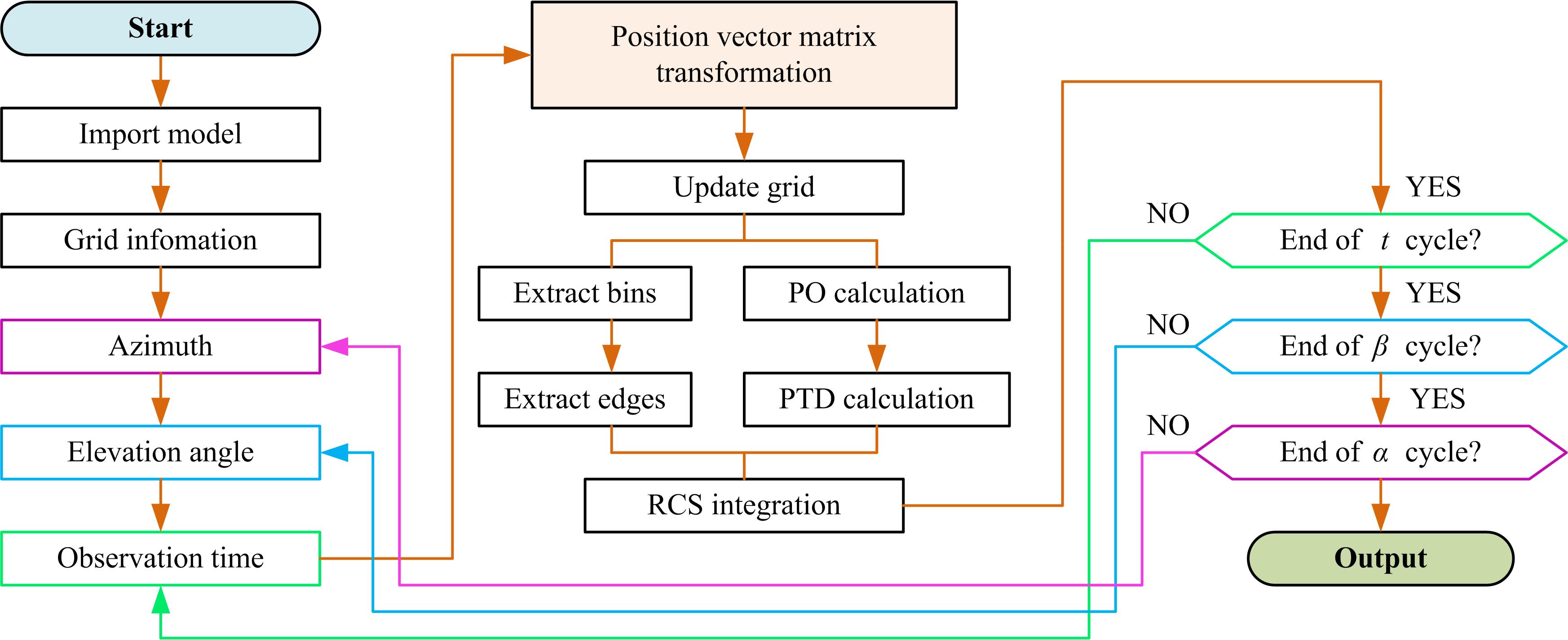
Figure 2. Flow chart of rotor dynamic scattering calculation method.
Modern helicopters are moving toward high speed and stealth while pursuing more excellent aerodynamic and handling characteristics [1,2], such as X2 (Sikorsky, City of Stateford, CT, USA), Tiger (Eurocopter, Paris, France), and RAH-66 (Boing, Chicago, USA) [3]. Due to the rotating parts such as the main rotor and the tail rotor, the research on the dynamic electromagnetic scattering characteristics of helicopters has always been a difficult point.
Low detectability technology is widely used in helicopters, fighter jets, and missiles, requiring the consideration of radar stealth for important components from the beginning, including cockpits, exhaust systems, and rotors [4,5]. The main rotor is the most important aerodynamic part of the helicopter, while the high-speed rotating rotor makes the aircraft have unique flight behavior and maneuverability [6,7]. However, the aerodynamic design of the rotor also affects its stealth characteristics [8,9]. Using the Maxwell equations as the main control equations, a set of numerical calculation methods for the rotor radar cross-section (RCS) characteristics based on the time-domain finite volume method is established. For the calculation of static electromagnetic scattering characteristics, the RCS solution of the helicopter is the same as the RCS solution of the fighter or unmanned fighter [10,11]. However, in the face of the high-speed rotation of the rotor, the static calculation obviously cannot reflect or meet the actual dynamic scattering characteristics of the helicopter.
Using the quasi-static principle (QSP) to discrete time series, the periodic rotary motion of the blades is decomposed into transient states, and the dynamic RCS response characteristics of the rotor are studied [12]. This method is simple and easy to understand and can be widely used in the motion simulation of rotor parts of helicopters or rotorcrafts [13,14], while it cannot achieve instantaneous calculations at a large number of points in time, nor can it reflect the continuity of rotor RCS changes. The geometric model of the rotor is established with NACA0012 as the blade airfoil, while the physical optics (PO) and an equivalent current method are used to calculate the rotor RCS under various motion conditions [15,16]. For less computer time, the grid transformation process using the body coordinate system and grid adaptive technology is applied to existing cavitation algorithms [17]. For multi-section topographical surfaces, a narrow surface element method is used to update a large amount of mesh data to optimize its radar cross-section [18]. Grid transformation technology can also be found in global ocean models and constant volume transformations [19,20]. Therefore, when considering the rotary motion of the rotor [21,22], the ideas of these mesh regeneration techniques can be implanted into a new dynamic simulation method and then used to calculate the dynamic RCS of the rotor.
Historically, research on the radar stealth of helicopters and rotor components is mostly based on quasi-static methods, and their calculation results are also static RCS or a small number of quasi-static results [23,24]. The core of QSP is to discretize many sample states. This approach is very cumbersome and laborious when facing the paddle angle, fuselage attitude angle, and multi-rotor. The relativistic law converts the rotation angle to the observation angle, which cannot deal with the situation when the fuselage or multiple rotors exist at the same time [15]. To overcome the shortcomings of these traditional methods, considering the complex effects of rotor rotation and tilt design [25,26], this paper attempts to establish a method for studying the dynamic electromagnetic scattering characteristics of the separate rotor and rotor plus its fixing device, and then it studies the radar stealth characteristics of helicopters and rotors at different attitude angles. It can be seen that studying the dynamic scattering of the rotor is of practical significance to the radar cross-section of the helicopter as a whole.
3. Data, Model, Applications and Influences:
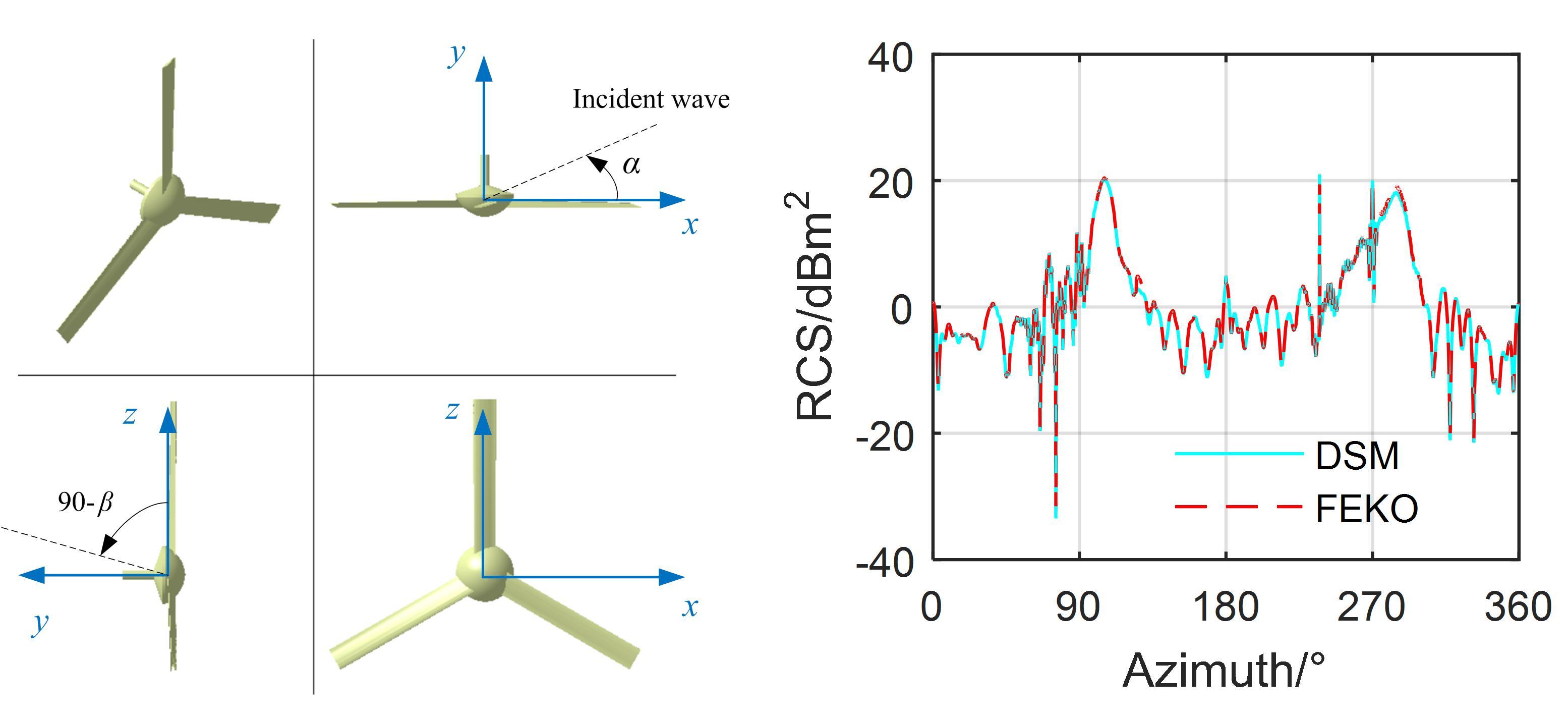
As shown in Figure 3. It can be seen that the RCS curve at this time generally shows two large bumps, which are located on the left and right sides of the tail rotor, respectively; this is because the lateral illumination area of the tail rotor is large, and many strong scattering sources will appear.
|
(a) tail rotor model |
(b) RCS curve |
Figure 3. The radar cross-section of the tail rotor, fR = 5 GHz, α = 0°~360°, β = 0°, t = 0 s.
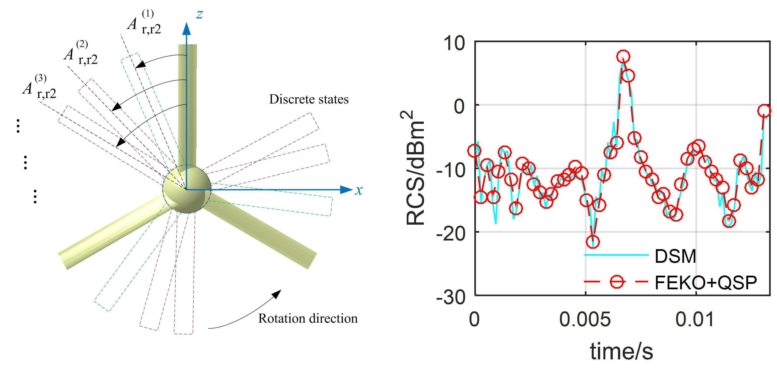
For the dynamic RCS as shown in Figure 4, the tail rotor RCS curve determined by DSM fluctuates and shows a peak (6.71 dBm2 at t = 0.0067 s) during the current observation time. The two RCS curves are generally consistent, and the mean value of the DSM curve is 0.429 dBm2 smaller than the other.
|
(a) QSP schematic [12,15] |
(b) Dynamic RCS |
Figure 4. Dynamic RCS on the tail rotor, fR = 5 GHz, α = 60°, β = 0°, nr2 = 1500 r/min.
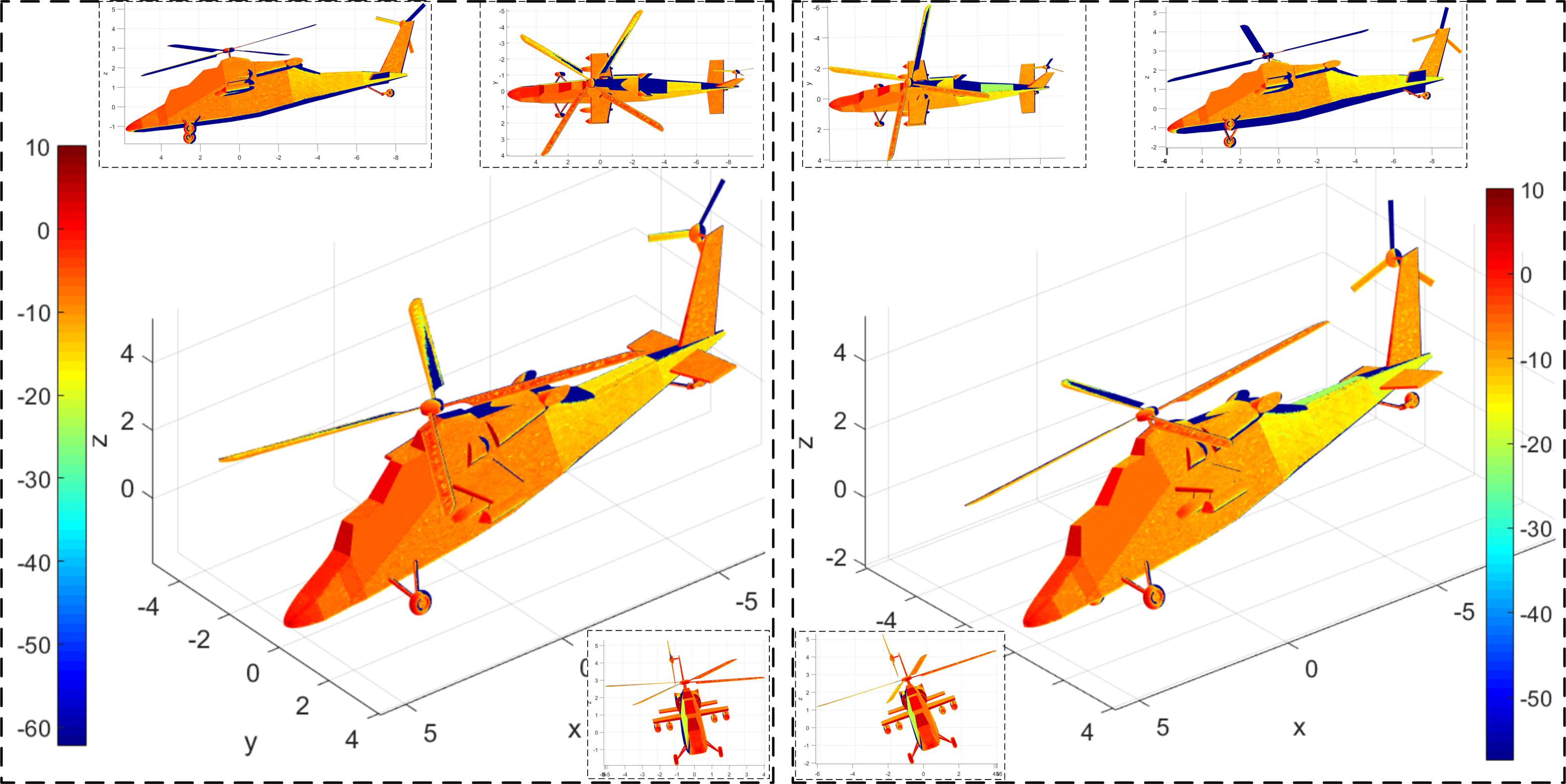
Figure 5 presents that the rolling angle has a significant effect on the dynamic electromagnetic scattering characteristics of the helicopter surface. For Figure 16a, the main rotor rotates 58° and the tail rotor rotates 174°. At this time, a large area of deep red appeared on the nose and the front of the cockpit, the front of the main rotor hub shows a transition from dark red to red, the surface of some main rotor blades has more red, the front of the landing gear and short wings are also dark red concentrated, tail rotor hub and vertical tail show red. For Figure 16b, the main rotor rotates 168° and the tail rotor rotates 504°, where the red area on the main rotor surface is significantly reduced and the dark blue area is increased, while the large red and yellow areas on the fuselage surface have also become lighter, including the nose, cockpit, fuselage side, tail beam, horizontal tail, and vertical tail. The increase in roll angle increases the tilt angle between the side of the fuselage and the radar wave, making it easier for the incident wave to be scattered to the upper and rear areas. This change is also applicable to the interpretation of the special changes in the scattering of the vertical tail lighting. However, the overall effect of deflecting radar waves in its lighting area has not been improved because the main rotor's hub is designed as a rotating body (combination of ellipsoid and cylinder). These results indicate that it is feasible for DSM to describe the effect of attitude angle changes on helicopter dynamic RCS.
|
(a) γ = 10°, t = 0.0193 s |
(b) γ = 20°, t = 0.056 s |
|
(a) γ = 10°, t = 0.0193 s |
(b) γ = 20°, t = 0.056 s |
Figure 5. Effect of rolling angle on helicopter surface scattering, nr1 = 500 r/min, nr2 = 1500 r/min, fR =5 GHz, α = 30°, β = 0°, θ = −10°.
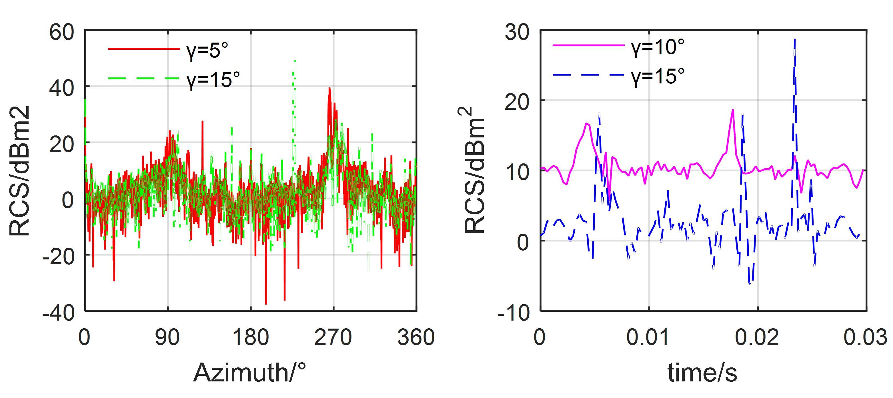
Figure 6 provides that the rolling angle has a significant effect on both the instantaneous and dynamic RCS of the helicopter. For Figure 17a, the RCS curves at γ = 5° and 10° are generally similar, but there are large differences in the local fluctuations and peaks, where the maximum value of the RCS curve at γ = 5° is 39.55 dBm2 at 265.5°, while that of the RCS curve at γ = 15° is 50.92 dBm2 at 228°. In addition, the difference between the two RCS curves in the azimuth ranges of 71–114.5° and 224.3–291° mostly exceeds 10 dBm2, because when the roll angle is changed, the electromagnetic scattering characteristics of the fuselage have changed greatly, and the main rotor and tail rotor also make a certain contribution to the lateral RCS. However, the influence of the fuselage is still major, so these two RCS curves are similar. For Figure 17b, the RCS curves at γ = 10° and 15° both show dynamic characteristics, and the average RCS value of the former is 4.54 dBm2 higher than the latter. The RCS curve at γ = 10° shows two large peaks, 16.72 dBm2 at 0.0042 s and 18.71 dBm2 at 0.0177 s, while the RCS curve at γ = 15° shows three large peaks, 18.26 dBm2 at 0.0054 s, 18.22 dBm2 at 0.0186 s, and 28.8 dBm2 at 0.0234 s. The reason for these changes is mainly that the rotation of the tilted main rotor brings dynamic electromagnetic scattering characteristics to the helicopter, plus the dynamic scattering contribution of the tail rotor. Table 7 provides the average RCS of the helicopter at different roll angles, showing that the average RCS of the helicopter reaches 40.81 dBm2 at γ = 0°, while the average RCS of the helicopter is only 10.41 dBm2 at a roll angle of −20°. These results indicate that the roll angle has a greater impact on the RCS of the helicopter, but it still cannot cover the dynamic changes brought about by the rotor components.
|
(a) t = 0.0207 s |
(b) α = 290° |
Figure 6. Effect of rolling angle on helicopter RCS, nr1 = 500 r/min, nr2 = 1500 r/min, fR = 5 GHz, β = 0°, θ = −10°.
The RCS of the main rotor and tail rotor is indeed dynamic and periodic, and their periodic characteristics are related to the rotation speed and attitude angle. Increasing the rotor speed can significantly reduce its dynamic RCS period, but it cannot change its fluctuation amplitude and peak value. Azimuth and elevation angle are also important factors affecting helicopter RCS. When the radar wave illuminates the tail rotor disc vertically, the dynamic RCS characteristics of the tail rotor are negligible. The pitching and rolling angles have a large impact on the static and dynamic RCS of the helicopter, but they still cannot cover the dynamic electromagnetic scattering characteristics brought by the main rotor and tail rotor.