Your browser does not fully support modern features. Please upgrade for a smoother experience.
Please note this is a comparison between Version 1 by Mohamad Emad M Alabdulkarim and Version 4 by Rita Xu.
The field of high-pressure materials research has grown steadily, with many remarkable discoveries having been made. Recent progress in
The field of high-pressure materials research has grown steadily over the last seven decades, with many remarkable discoveries having been made. This work is summarising recent progress in
laser
material processing within
diamond anvil cells
(L-DACs); researchers focus on the practice of
laser-driven dynamic compression
within diamond anvil cells (i.e.,
LDC–DAC
experimentation).
- laser dynamic compression
- diamond anvil cell
- isentropic compression
1. Introduction
Since the 1930′s, investigators have developed increasingly capable pressure generating devices, such as lever-arm presses [1], piston-driven presses [2], and opposed anvil presses [3][4][3,4]; this has enabled materials to be studied at successively higher static pressures over time [5]. In the mid-20th century, Charlie Weir et al. invented the first diamond anvil cell (DAC), in which samples were observed directly through diamond anvils at pressures of over 3 GPa [6]; this revolutionised high pressure materials research, making it possible to monitor phase changes and chemical reactions as pressure was applied [6]. Soon thereafter, laser beams were introduced into DACs for the first time (to process materials) by Takahashi and Bassetta [1].
An apparatus that focuses a laser beam between diamond anvils to heat, shock, or induce chemical reactions within a sample, is known as a laser diamond anvil cell (L-DAC) [7]. L–DAC systems have opened a door to entirely new research fields, such as the measurement of material properties at high pressures and high temperatures (HPHT) [8][9][10][11][12][13][14][8,9,10,11,12,13,14] or the study of extremophile biological organisms at pressures similar to those extant at hydrothermal vents [3][15][3,15]. Figure 1A illustrates how the number of journal articles involving L–DAC experiments has risen steadily since the early 1990′s—and is now approaching 60–70 articles per year (blue curve).

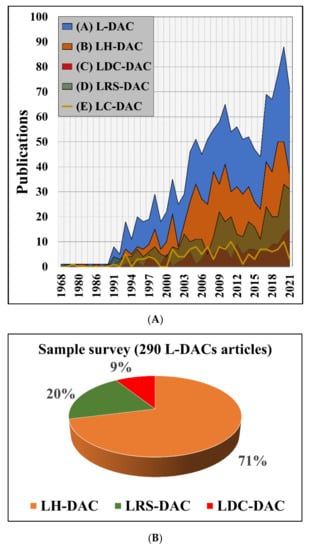
Figure 1. (A) Total annual scientific production for all L–DAC studies [Blue] compared with laser heated DAC (LH–DAC) [Orange], laser reactive synthesis DAC (LRS-DAC) [Green], and laser-driven dynamic compression DAC (LDC–DAC) [Red] studies [7]. (B) Comparison of the total number of articles produced in each.
The three parts of this review are based on the primary modes of material modification presented in Figure 1A,B. Part I of this series summarises the more common laser-heated diamond anvil cell (LH–DAC) mode of experimentation (71% of papers) [7]. This paper (Part II) focuses on dynamic material compression within DACs using intense pulsed lasers, rather than laser heating samples. ResWearchers refer to this as laser-driven dynamic-compression diamond anvil cell (LDC–DAC) experimentation (9% of papers). The LDC–DAC mode is distinguished from other L–DAC modes through the presence of a pressure-wave or shockwave that considerably modifies a sample material’s structure/composition, and where heating is a secondary contributor, if present at all. Part III reviews the application of lasers to induce chemical reactions within diamond anvil cells (20% of papers); this latter method is dubbed laser reactive synthesis diamond anvil cell (LRS-DAC) experimentation. Although noteworthy reviews have previously outlined the development of DACs and high pressure research methods [1][5][6][14][16][17][18][1,5,6,14,16,17,18], this review speaks to laser materials processing—where all three modes of material modification/synthesis are described [19][20][19,20]. While the LH–DAC mode has been a principal driver throughout early L–DAC research [1], applications have now diversified, and interest is shifting toward the LDC–DAC and LRS-DAC modes—as evidenced by the Red/Green plots of Figure 1A.
This article (Part II), provides the key physics, historical events, and recent developments of LDC–DAC experimentation. Tables of materials modified/synthesised via LDC–DAC systems are given along with their corresponding process conditions of static pressure, shock pressures, temperature rises, and laser source wavelengths/energies (where available). TheOur intent is for the article to act as a field guide for others in setting-up and conducting their own high-pressure LDC–DAC research endeavours. Note that only laser-induced dynamic compression within DACs is considered here; neither light-gas gun experiments (without driving lasers) nor laser-induced shock compression (without transparent anvils) will be discussed in this review.
As further evidenced in this article, LDC–DAC experimentation provides researchers with a singular route to attaining extreme pressures across a large cross-sectional area (with pressures up to 1 TPa, thus far); the method is especially interesting as a multiplicative effect between the DAC pre-compression and the laser dynamic compression (LDC) has been documented [21]. This is well beyond the pressures attainable with single-stage hydrostatic or gas-membrane-driven diamond anvil cells [20][22][20,22] where otherwise multiple stages and/or nano-scale surface areas are required to attain such pressures [23].
LDC–DAC experimentation has enabled condensed matter physicists to determine material densities, melting curves, Hugoniot curves, equations of state (EOS), and transport properties for many common elements and compounds over a wide variety of conditions [19][20][24][25][26][27][19,20,24,25,26,27]. Furthermore, LDC–DAC methods have enabled geophysicists and planetary physicists to determine the properties of dense matter at conditions akin to those deep within planetary interiors, providing insight into the structure and dynamics present within the terrestrial planets [19][28][19,28]. The technique has allowed researchers to better understand how lasers interact with matter—and how shock-/pressure-waves travel through materials at high pressures [27][29][27,29]. Although multi-stage DACs can achieve pressures greater than 380 GPa, when sample sizes greater than 20 μm across are to be compressed, the LDC–DAC mode is presently the primary means to achieve pressures >> 380 GPa [19][30][31][32][19,30,31,32].
Alternative methods similar to, but distinguished from LDC–DAC processing are confined laser shock compression (e.g., explosive compression inside crystals) [33][34][33,34], open-atmosphere laser-driven dynamic compression (OA–LDC) [32][35][32,35], and high-power, multi-beam, laser-driven dynamic compression (HP–MB–LDC) [36][37][36,37]; all of these methods are generally conducted without the use of pre-compression within a diamond anvil cell, so they are excluded from this review. However, it is important to note that materials processing has indeed been carried out using these methods. For example, in the latter case (HP–MB–DC), the world’s highest-ever recorded pressures while synthesising novel materials was achieved (≈1.5 and 5 TPa) and high-pressure forms of Si–C and diamond were realised [37][38][37,38]. Even greater pressures have been achieved by HP–MB–DC methods (to 100 TPa) during plasma fusion experiments, but without synthesising any intended material [39][40][39,40]. However, OA–LDC and HP–MB–LDC methods typically require large facilities with multiple laser sources, e.g., the National Ignition Facility (NIF) or OMEGA Laser Facility [30], which have traditionally been outside the scope of many researchers. That said, the availability of high-peak-power lasers is growing rapidly, with new capabilities in short-laser pulse lasers becoming widely accessible at a reasonable cost [41][42][43][44][41,42,43,44].
2. Overview of Laser Dynamic Compression in Diamond Anvil Cells (LDC–DACs)
A typical laser-driven dynamic compression diamond anvil cell (LDC–DAC) experiment is illustrated in Figure 2A–D. LDC–DAC systems include a pulsed laser system ((i), not shown), a focused laser beam (ii), a material sample to be compressed (iii), at least one diamond anvil (iv), a chamber gasket (v), and an optional laser target (xvii) placed at the laser focus. Diamond is commonly used for the transparent anvils (iv) in LDC–DAC experiments due to its high shock impedance, wide transmission bandwidth, and dielectric constant [22], although other materials, such as sapphire (Al2O3) and quartz (SiO2), have been utilised [32][45][46][47][32,46,47,48].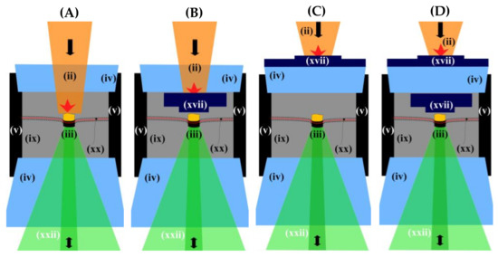
Figure 2. Illustrations of laser-driven dynamic compression diamond anvil cell (LDC–DAC) experiments. (A) The sample of interest is the target, (B) a separate target inside the anvil, (C) a target outside the anvil, and (D), a target outside and driver inside the anvil. Please see article text for component descriptions.

Figure 3. P–T diagram of L–DAC experimentation, showing region investigated by LDC–DAC systems (Red) [21][28][30][56][57][58][59][71][72][21,28,30,57,58,59,60,73,74], LH–DAC systems (Orange) [8][20][73][74][75][76][77][78][79][80][81][82][83][84][85][86][87][88][89][90][91][92][93][94][95][96][97][98][99][100][101][102][103][104][105][106][107][108][109][110][111][112][113][114][115][116][117][118][119][120][121][122][123][124][125][126][127][128][129][130][131][132][133][134][135][136][137][138][139][140][141][142][143][144][145][146][147][148][149][150][151][152][153][154][155][156][157][158][159][160][161][162][163][164][165][166][167][168][169][170][171][172][173][174][175][176][177][178][179][180][181][182][183][184][185][186][187][188][8,20,75,76,77,78,79,80,81,82,83,84,85,86,87,88,89,90,91,92,93,94,95,96,97,98,99,100,101,102,103,104,105,106,107,108,109,110,111,112,113,114,115,116,117,118,119,120,121,122,123,124,125,126,127,128,129,130,131,132,133,134,135,136,137,138,139,140,141,142,143,144,145,146,147,148,149,150,151,152,153,154,155,156,157,158,159,160,161,162,163,164,165,166,167,168,169,170,171,172,173,174,175,176,177,178,179,180,181,182,183,184,185,186,187,188,189,190], and LRS–DAC systems (Green) [189][190][191][192][193][194][195][196][191,192,193,194,195,196,197,198]. For reference, P–T markers are also provided for several geophysical locations, including the P–T at a depth of 250 km of Europa’s oceans [197][199], 60–5100 km underneath the Earth’s surface [59][103][159][60,105,161], 12 × 103 km-deep in Neptune’s core [198][200], (20 to 71.5) × 103 km-deep in Jupiter’s core [199][200][201,202] and two LDC experiments with ramp -compression [37][38][37,38].
1 ns) were employed to ensure both strong shock loading and heating of the samples [26].
A primary advantage of the LDC–DAC experimental mode is the ability to control initial-, peak-, and final-conditions (ρ-P-T - - ) of the sample material. For example, initial densities of a sample are controlled via (isothermal) compression within a DAC prior to delivering a laser shock, while the maximum (peak) compression is obtained through the laser fluence, pulse width, pulse shape, and target/sample geometries. By conducting the experiment within a DAC, the material arrives at a final, elevated pressure, making it possible to preserve metastable states that would otherwise deteriorate at lower pressures (which sometimes happens when using LDC alone) [22].
Nevertheless, LDC–DACs do have some limitations, and as shown in Figure 1B, comprise only a minor fraction of all L–DAC publications. This may in part be due to the complexity of the experiments and/or lack of access to the necessary high-energy laser sources [19]. In addition, there is a limited selection of material characterisation probes that can be used during LDC–DAC experiments, where real-time, ultrafast characterisation is required. One important complication is the requirement for custom anvil shapes—often thick on the opposing (diagnostic) anvil (iv), and thinned on the incident (drive beam) anvil (iv)—and specialty shapes are often needed along the laser beam path [25]. The opposing anvil material must also be designed to have high impedance matching with the sample [31].
Of course, a significant limitation is the strength of the anvil materials in their required geometries. Diamond is the most commonly-used anvil material, yet it is often thinned to <400 micron thicknesses on the incident anvil [56][57]. Diamond anvils are subject to failure during compression experiments, which raises the experimental cost, and requires significant effort to reset the LDC–DAC system for subsequent runs. Although sapphire has lower compressive strength (~2 GPa static, ~21 GPa dynamic) than diamond (~35 static, ~98 GPa dynamic), it has also been used as an anvil material during LDC–DAC experiments [32][45][202][203][204][32,46,203,204,205]. Similarly, quartz has also been used as an anvil or window (~1 GPa static, ~9 GPa dynamic) [205][206][206,207]. Further research is required to maximise the peak pressures attained during shock loading and minimise the cost/effort of LDC–DAC experimental runs [48][49].