Your browser does not fully support modern features. Please upgrade for a smoother experience.
Please note this is a comparison between Version 2 by Rita Xu and Version 1 by Yevgeny Golubev.
The progress in the practical use of glassy carbon materials has led to a considerable interest in understanding the nature of their physical properties. The electrophysical properties are among the most demanded properties. In nature, in the course of geological processes, disordered
sp2
carbon substances were formed, the structure of which is in many respects similar to the structure of glassy carbon and black carbon, and the electrical properties are distinguished by a high-energy storage potential and a high efficiency of shielding electromagnetic radiation.
- natural disordered sp2 carbon
- molecular and super-molecular structure
- electrical and thermal conductivity
1. Introduction
In recent years, the number of studies reporting the successful use of disordered sp2 carbon (Dsp2C) materials in various technological processes is growing. A recent review article about the use of synthetic glassy carbon in advanced technological applications [1] clearly shows rapid technological progress in this field. At the same time, the production of materials with a glassy carbon structure is associated with several environmentally dirty processes. In the earth’s crust, “ready-made” Dsp2C is quite common, and its use in technology will be cheaper and more environmentally friendly than its synthetic structural counterparts. In addition, the natural origin provides a variety of precursors and physicochemical characteristics of formation processes in different geological settings, which allows reducing the cost of laboratory production of certain types of carbon materials to study the effect of changes in various structural and chemical parameters in the experiment. One of the most demanded properties of Dsp2C is its electrical conductivity, which, in combination with thermal and chemical stability, gives good prospects in the industry.
2. Formation of Disordered sp2 Carbon in Nature: Thermodynamic Conditions, Carbon Sources, Processes
Hydrocarbon compounds (primarily petroleum and bitumen) under the physicochemical conditions of the earth’s crust are transformed in the direction of carbonization (or dehydrogenation), with the elimination of most non-carbon components (Figure 1) [2], and in the direction of graphitization as a structural rearrangement of the aromatic skeleton formed during carbonization into a stable-layered graphite structure (sp2-hybridized) [3,4,5][3][4][5]. The process of graphitization of hydrocarbon compounds is irreversible, but it is not always terminated with the formation of graphite, both in terms of structure ordering and in terms of removal of hydrogen, oxygen, nitrogen, and sulfur heterocompounds. Condensation of carbonaceous matter can occur at the stage of formation of graphite-like nanostructures of various degrees of order and sizes [6] and can also end with the formation of structures such as multilayer ribbons and fullerenes [7,8][7][8]. In the sequence of carbonization (dehydrogenation) of hydrocarbon compounds, according to their physicochemical properties, a class of substances of the highest degree of transformation (carbonization) was distinguished, which was characterized by the so-called pre-graphite structural stage [9,10,11][9][10][11]. Such substances are distinguished by an almost pure carbon composition (usually over 95%) and the absence of solubility in organic solvents (for example, chloroform), and their distinctive physical property is electrical conductivity. According to the indicated properties, these substances are similar to graphite, while their critical difference with graphite is the absence of a bulk crystal structure (three-dimensional hkl reflections on X-ray and electron diffraction patterns). There is only two-dimensional graphite-like ordering as the proximity of interplanar distances to the 002 graphite plane. Dsp2C is porous, and accordingly has a lower density (1.5–2.2) and a larger specific surface area than graphite.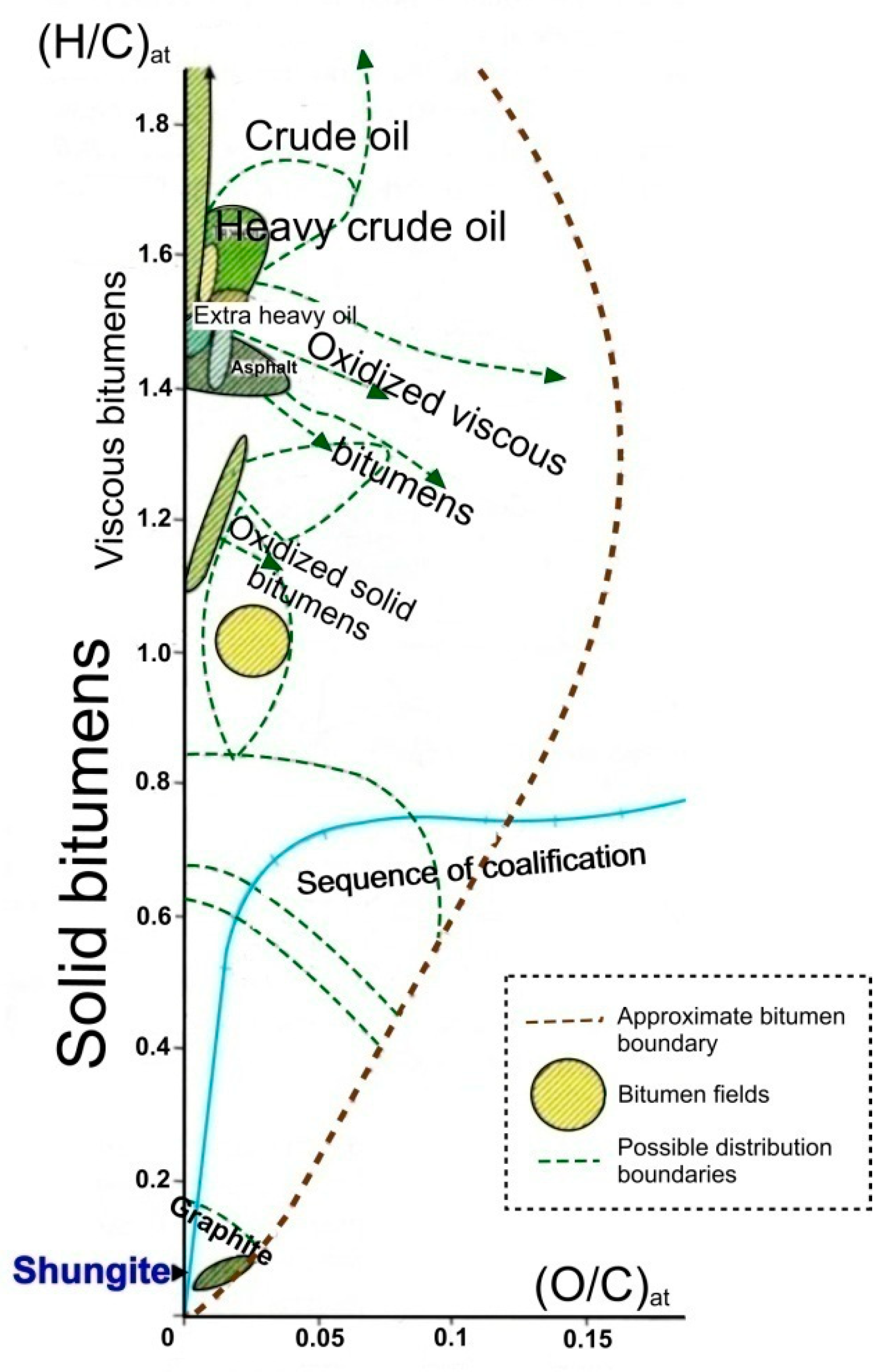
Figure 1. Van Crevelen diagram of carbonization (dehydrogenation) showing the alteration of H/C atomic ratios versus O/C. Dsp2C (represented by shungite) is limited to a narrow region close to the end member of pure carbon (adapted from [2]).
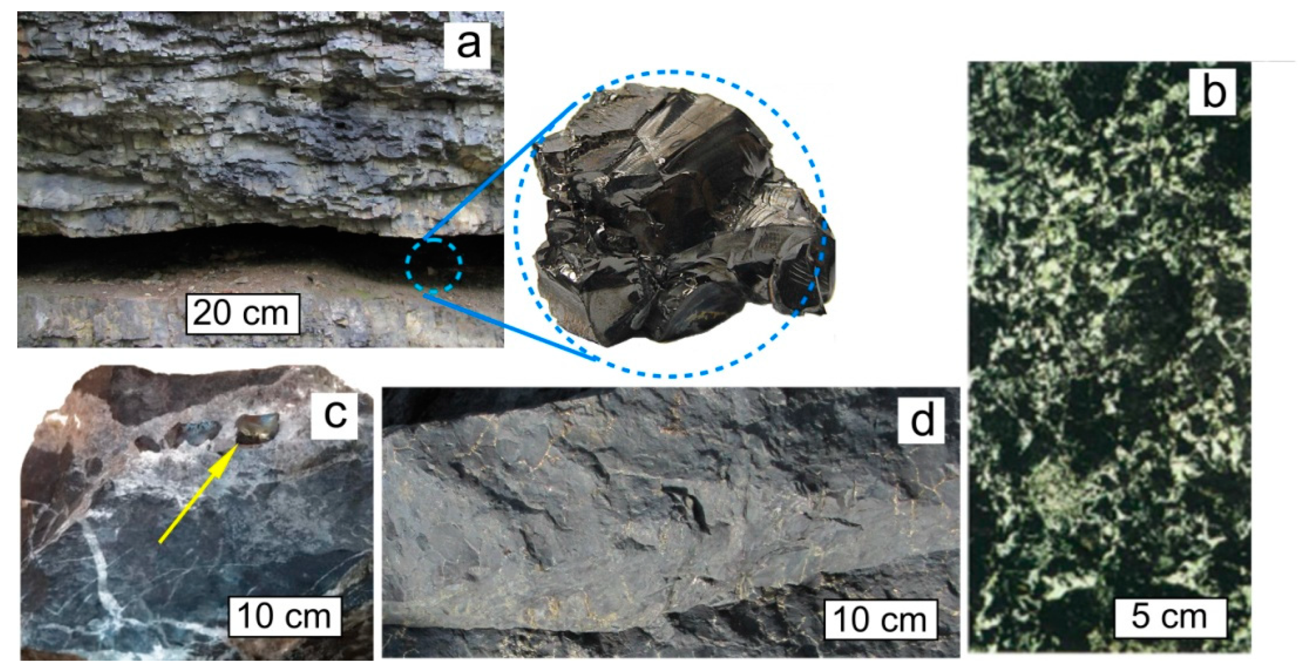
Figure 2. Typical occurrences of natural Dsp2C: shungite carbon vein (Shunga occurrence, Karelia), with a typical sample in the inset (a). Cluster form of inclusions of Dsp2C in the rock, Zazhogino occurrence, Karelia (b). Dsp2C isolations as grains (indicated by yellow arrow) in a calcite vein, occurrence Rucheynoye, Kozhim River, Subpolar Urals, Russia (c). Rock (quartzite) impregnated with Dsp2C, Maksovo occurrence, Karelia (d).
3. Structural Characteristics and Models of Natural Disordered sp2 Carbon
The object of ourthe consideration is Dsp2C, which makes its structural characteristics ambiguous. It does not graphitize during high-temperature (up to 2900 °C) treatment [38] under normal pressure conditions. The development of physicochemical methods allowed determining some structural features and chemical composition, but electron and X-ray amorphism still does not allow to unambiguously describe its structure. For example, at different times, the carbon of shungites was defined by researchers as weakly ordered graphite [39], amorphous carbon [4], natural metastable non-graphitic carbon [40], natural glassy carbon [41], and fullerene-like carbon in the group of non-graphitic natural carbonaceous substances [42,43][42][43]. In this section, the main models of the structure of natural Dsp2C are considered, primarily using shungite carbon as an example.3.1. Molecular Structure
The basis of the molecular structure of natural Dsp2C is a graphene grid. The size and shape of these grids vary depending on the type of supramolecular structure to which the grid belongs. The following main supramolecular structures were found in natural Dsp2C: turbostratic stacks of graphene layers (grids), multilayer ribbons, fully enclosed multilayer globules, and partially closed multilayer cups (Figure 3).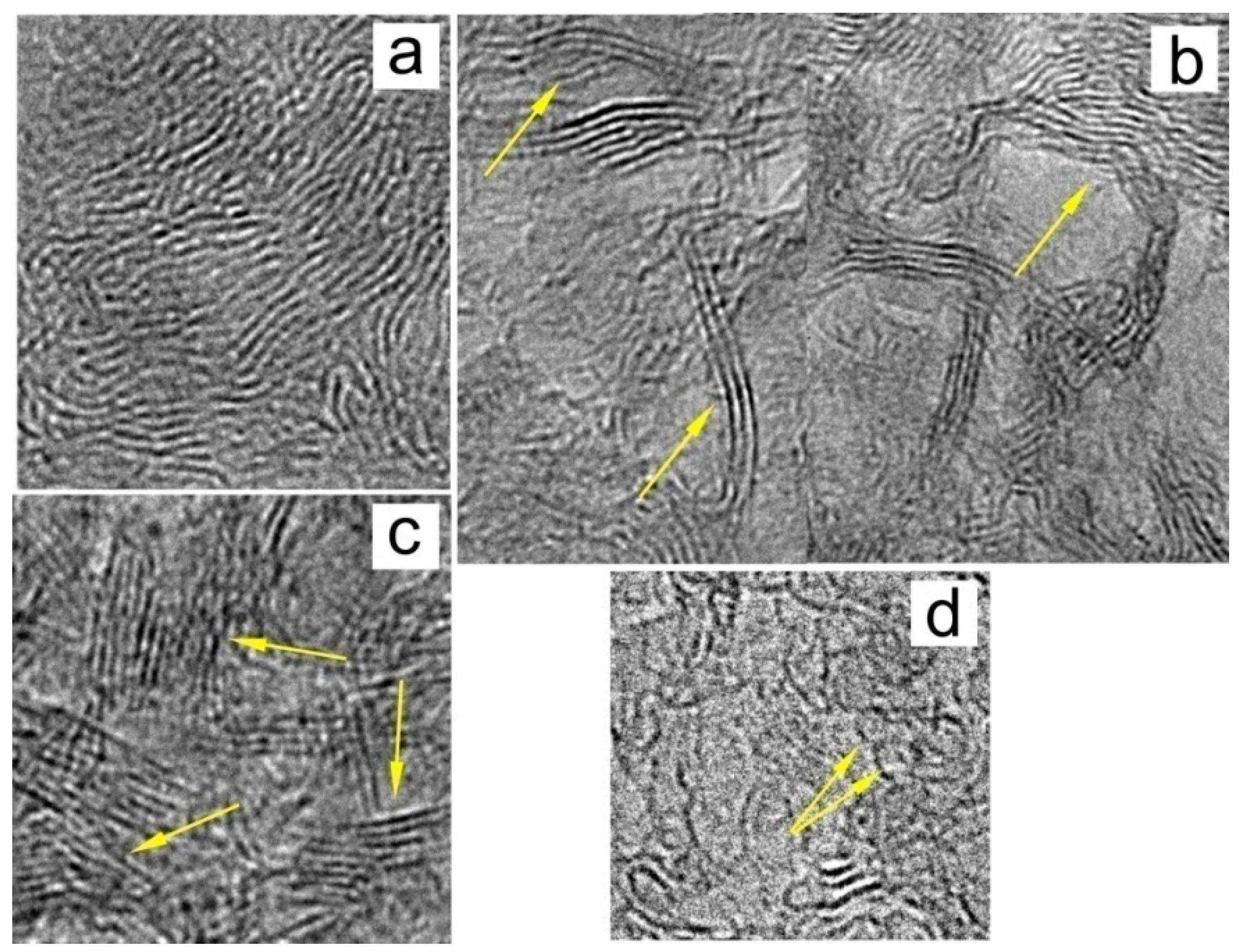
Figure 3. Basic structures of Dsp2C: (a) typical entangled structure, (b) ribbon structure, (c) stacks of graphene layers, and (d) fullerene-like single-layer and multilayer structures.
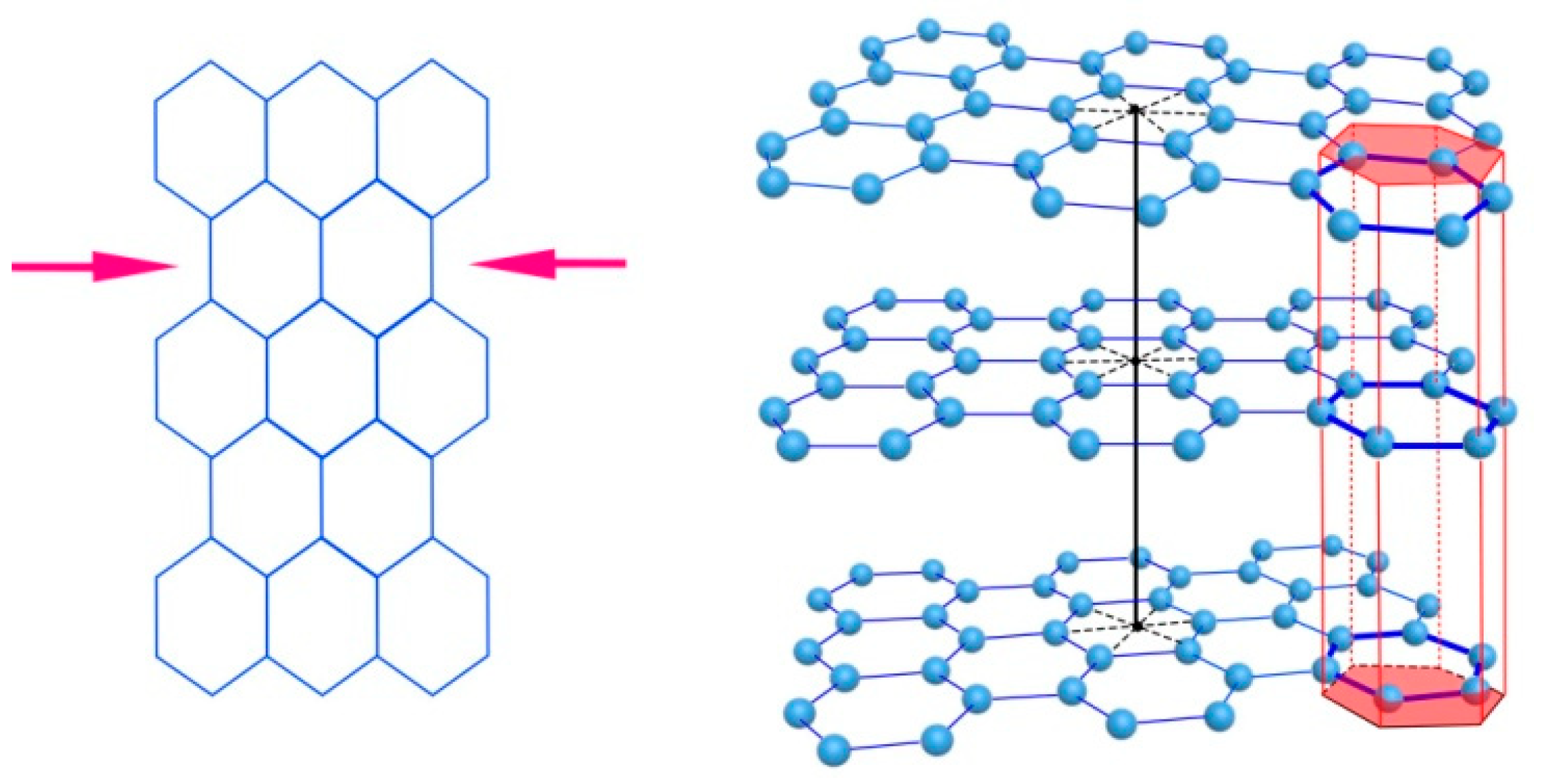
Figure 4. Deformation of a graphene layer (left) and displacement of flat graphene layers relative to each other in the stack (right).
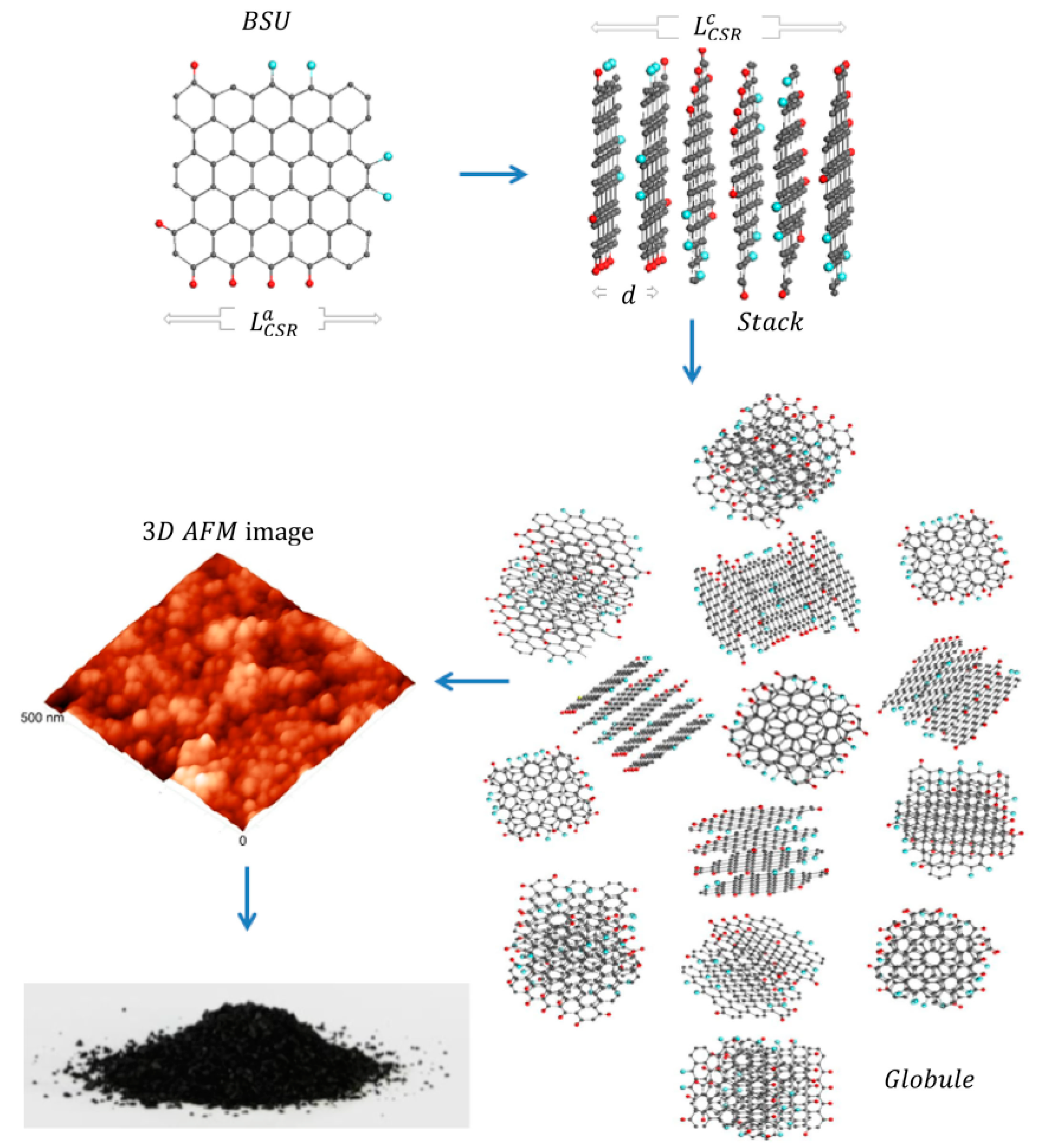
Figure 5. Scheme of the formation of a super-molecular globular structure of natural Dsp2C (from [52]) through the formation of a stack of graphene layers as basic structural units (BSU) with subsequent aggregation of stacks into a rounded particle (globule). The globules are shown in an atomic force microscope (AFM) image. Along the edges of graphene molecules are heteroatoms (hydrogen (red balls) and oxygen (blue balls)).
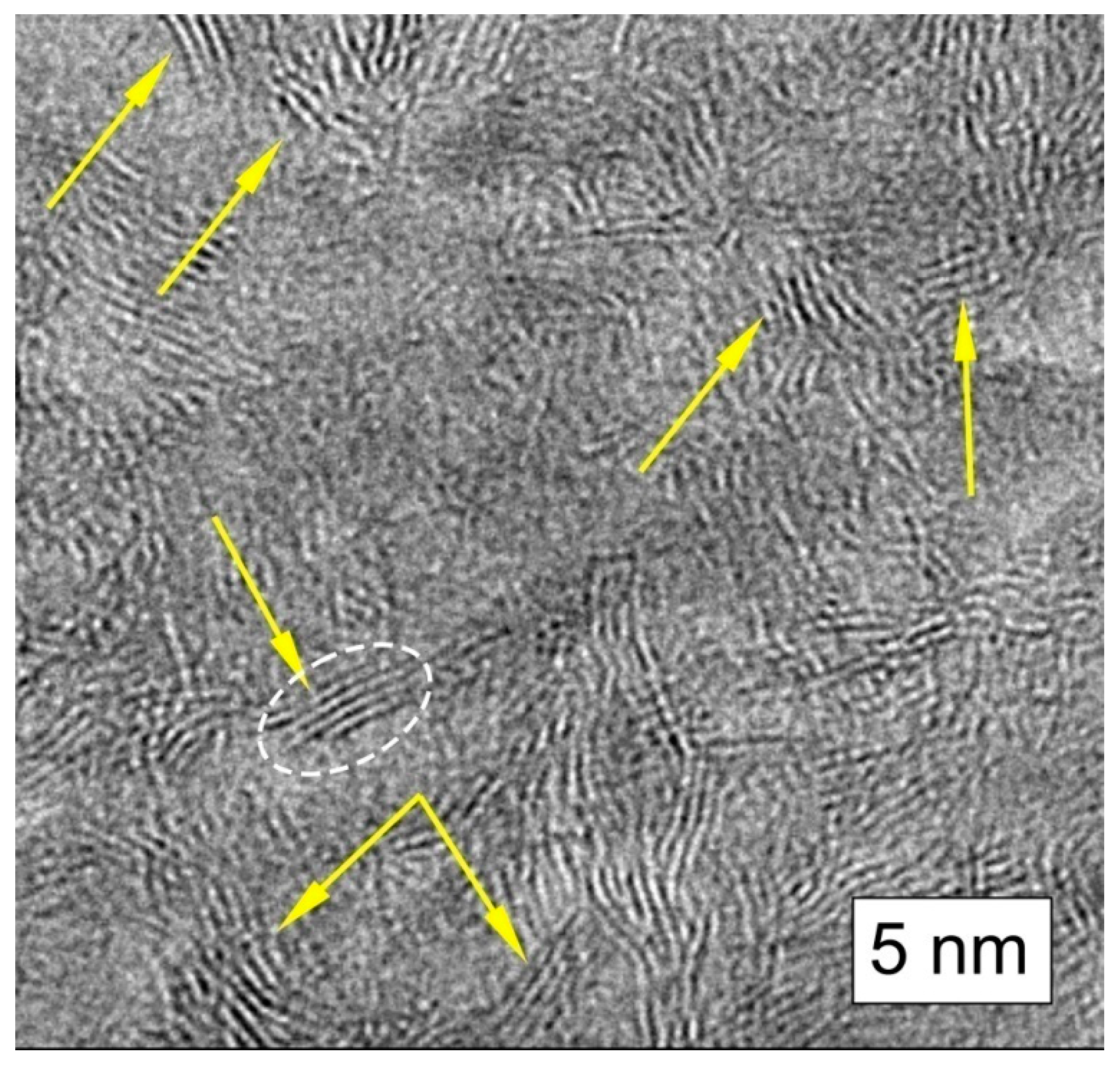
Figure 6. Chaotically oriented stacks of graphene layers in shungite carbon (indicated by yellow arrow).
3.2. Super-Molecular Structure
For a long time, the super-molecular structure of natural Dsp2C was not the focus of researchers. The interest of physicists and materials scientists in the super-molecular structure of Dsp2C drastically increased after the publication of fullerenes of geological origin found in Karelian shungites [18]. Earlier, Kovalevsky created a model where the fundamental element of shungite carbon is a fullerene-like globule. After publication [18], the Kovalevsky model for a long time became the dominant idea of the super-molecular structure of shungite carbon [60,61][60][61]. According to the model, a shungite globule is a spherical or ellipsoidal multilayer carbon formation about 10 nm in size, presumably with a pore inside (Figure 7). The main arguments in favor of the model are the presence of two types of pores (open and closed) in shungite carbon (see [44] and references therein), and the results of processing HRTEM images using the Cowley method [42].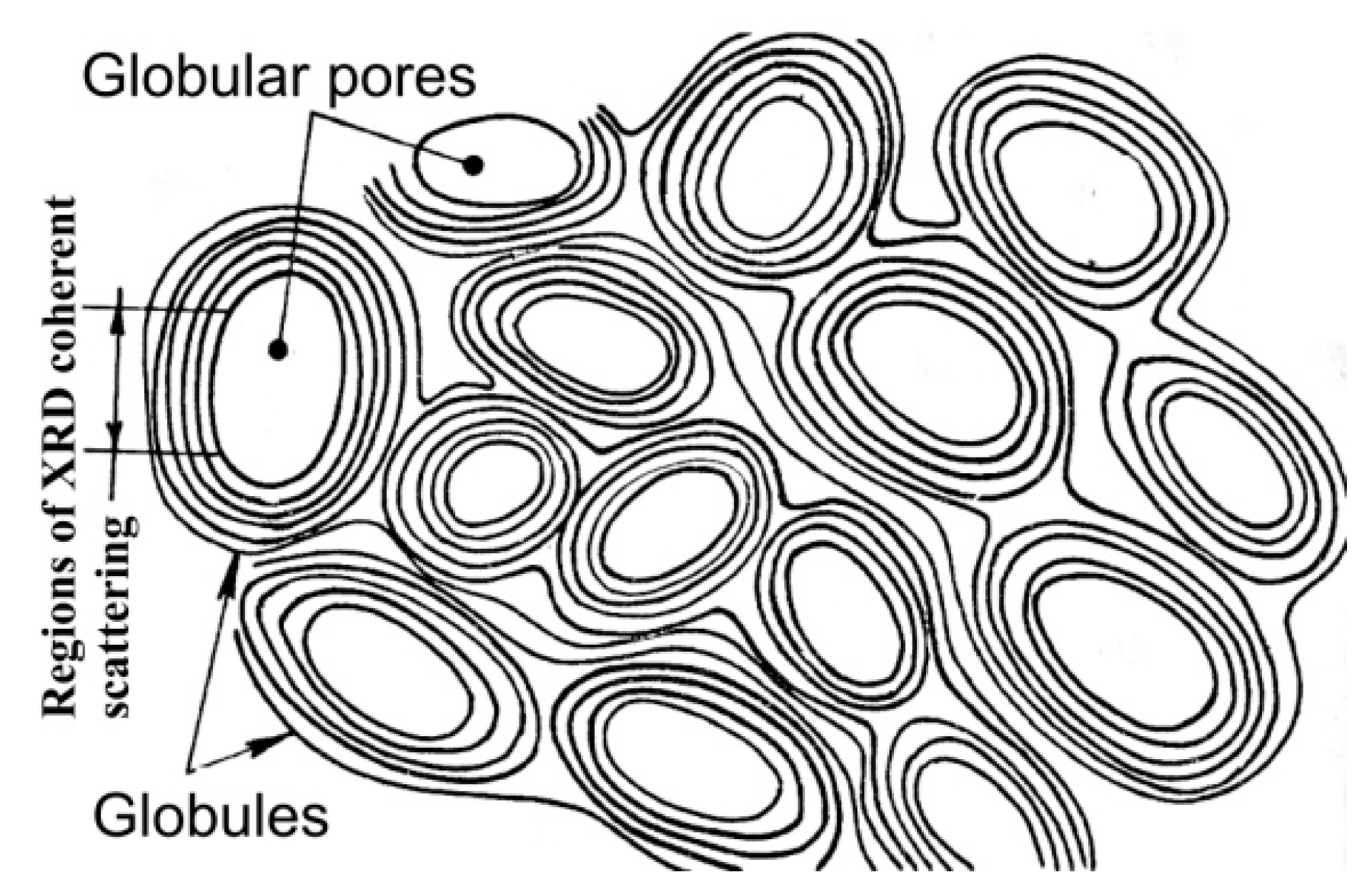
References
- Vieira, L.S. A review on the use of glassy carbon in advanced technological applications. Carbon 2022, 186, 282–302.
- Cornelius, C.D. Classification of Natural Bitumen: A Physical and Chemical Approach. In Exploration for Heavy Crude Oil and Natural Bitumen: AAPG Studies in Geology, 25; Meyer, R.F., Ed.; American Association of Petroleum Geologists: Tulsa, OK, USA, 1987.
- Oberlin, A. High-resolution TEM studies of carbonization and graphitization. In Chemistry and Physics of Carbon; Thrower, P.A., Ed.; Marcel Dekker: New York, NY, USA, 1989.
- Buseck, P.R.; Huang, B.J. Conversion of carbonaceous material to graphite during metamorphism. Geochim. Cosmochim. Acta 1985, 49, 2003–2016.
- Beyssac, O.; Rumble, D. Graphitic carbon: A ubiquitous, diverse, and useful geomaterial. Elements 2014, 10, 415–420.
- Golubev, Y.A.; Rozhkova, N.N.; Kabachkov, E.N.; Shul’ga, Y.M.; Natkaniec-Hołderna, K.; Natkaniec, I.; Antonets, I.V.; Makeev, B.A.; Popova, N.A.; Popova, V.A. sp2 amorphous carbons in view of multianalytical consideration: Normal, expected and new. J. Non-Cryst. Solids 2019, 524, 119608.
- Harris, P.J.F. New perspectives on the structure of graphitic carbons. Crit. Rev. Solid State Mater. Sci. 2005, 30, 235–253.
- Mélinon, P. Vitreous Carbon, Geometry and Topology: A Hollistic Approach. Nanomaterials 2021, 11, 1694.
- Uspensky, V.A.; Radchenko, O.A.; Glebovskaya, E.A. Basics of Genetic Classification of Bitumen; Nedra: Leningrad, Russia, 1964. (In Russian)
- Jakob, H. Nomenclature, Classification, Characterization and Genesis of Natural Solid Bitumen (Migrabitumen). In Bitumen in Ore Deposits; Parnell, J., Kucha, H., Landais, P., Eds.; Springer: Berlin/Heidelberg, Germany, 1993.
- Filippov, M.M. Anthraxolites; VNIGRI: Saint Petersburg, Russia, 2013. (In Russian)
- Filippov, M.M. Shungite-Bearing Rocks of the Onega Structure; Karelian Science Centre: Petrozavodsk, Russia, 2002. (In Russian)
- Filippov, M.M.; Cherevko, N.K.; Golubev, Y.A. Higher anthraxolites. Geol. Ore Dep. 2007, 49, 624–629.
- Melezhik, V.A.; Fallick, A.E.; Fillipov, M.M.; Larsen, O. Karelian shungite—An indication of 2.0-Ga-old metamorphosed oil-shale and generation of petroleum: Geology, lithology and geochemistry. Earth Sci. Rev. 1999, 47, 1–40.
- Pen’kov, V.F. Genetic Mineralogy of Carbonaceous Substances; Nedra: Moscow, Russia, 1996.
- Mossman, D.J. Carbonaceous Substances in Mineral Deposits: Implications of Geochemical Explorations. J. Geochem. Expl. 1999, 66, 241–247.
- Buseck, P.R.; Galdobina, L.P.; Kovalevski, V.V.; Rozhkova, N.N. Shungites: The C-rich rocks of Karelia, Russia. Can. Mineral. 1997, 35, 1363–1378.
- Melezhik, V.A.; Filippov, M.M.; Romashkin, A.E. A giant palaeoproterozoic deposit of shungite in NW Russia: Genesis and practical applications. Ore Geol. Rev. 2004, 24, 135–154.
- Buseck, P.R.; Tsipursky, S.J.; Hettich, R. Fullerenes from the Geological Environment. Science 1992, 257, 215–217.
- Glebashev, S.G.; Ignatiev, S.V.; Kovyazin, A.N. Formation and placement of shungite rocks in the Kyzyl zone (East Kazakhstan). Sov. Geol. 1989, 1, 33–42.
- Golubev, E.A.; Glebashev, S.G.; Ignatiev, S.V.; Filippov, V.N. Supramolecular structure of anthraxolite from the Bakyrchik deposit, East Kazakhstan. Vestn. IG Komi SC UB RAS 2006, 4, 4–7.
- Baigulbaeva, M.M.; Ongarbaev, E.K.; Tileuberdi, E.; Zhambolova, A.B.; Zhumakhan, K. Influence of mechanochemical activation on the composition, properties and structure of shungite rocks. Combust. Plasma Chem. 2021, 19, 149–156.
- Jehlička, J.; Rouzaud, J.N. Structural and micro textural features of solid bitumens from pillow lavas from Mitov (Barrandian Neoproterozoic, Bohemian Massif). Věstn. CGU 2000, 75, 297–306.
- Jehlička, J.; Svatoš, A.; Frank, O.; Uhlík, F. Evidence for fullerenes in solid bitumen from pillow lavas of Proterozoic age from Mítov (Bohemian Massif, Czech Republic). Geochim. Cosmochim. Acta 2003, 67, 1495–1506.
- Silaev, V.I.; Ilchenko, V.O.; Lyutoev, V.P.; Filippov, V.N.; Golubev, E.A.; Kovaleva, O.V. Authic Pseudomineralization in Anthraxolite. Problems of Geology and Mineralogy; Geoprint: Syktyvkar, Russia, 2006.
- Xiao, X.M.; Wang, F.; Wilkins, R.W.T.; Song, Z.G. Origin and gas potential of pyrobitumen in the upper proterozoic strata from the Middle Paleo—Uplift of the Sichuan basin, China. Int. J. Coal Geol. 2007, 70, 264–276.
- Thomson, J.E. On the origin of algal-like forms and carbon in the Sudbery basin, Ontario. Trans. R. Soc. Can. 1960, 54, 65–75.
- Youg, G.M. Tectono-sedimentary history of early proterozoic rocks of the northern Great Lakes region. Geol. Soc. Amer. 1983, 160, 15–32.
- Pye, E.G.; Naldrett, A.J.; Giblin, P.E.; Mineralization in the Whitewater group. The geology and ore deposits of the Sudbery structure Ontario geological survey. Ont. Geol. Surv. 1984, 1, 219–232.
- Mossman, D.J. Hydrocarbon habitat of the paleoproterozoic Franceville series, republic of Gabon. Energy Sources 2001, 23, 45–53.
- Mossman, D.J.; Nagy, B. Solid bitumens: An assessment of their characteristic, genesis, and role in geological processes. Terra Nova 1996, 8, 114–128.
- Tyler, S.A.; Barghoorn, E.S.; Barrett, L. Anthracitic coal from Precambrian upper huronian black shale of the Iron River district, northern Michigan. Geol. Soc. Am. Bull. 1957, 68, 1293–1304.
- Mancuso, J.I.; Kneller, W.A.; Quick, I.C. Precambrian vein pyrobitumen: Evidence for petroleum generation and migration 2 Ga ago. Precambrian Res. 1989, 44, 137–146.
- Buseck, P.R.; Beyssac, O. From Organic Matter to Graphite: Graphitization. Elements 2014, 10, 421–426.
- Bonijoly, M.; Oberlin, M.; Oberlin, A. A possible mechanism for natural graphite formation. Int. J. Coal Geol. 1982, 1, 283–312.
- Bustin, R.M.; Rouzaud, J.-N.; Ross, V. Natural graphitization of anthracite: Experimental considerations. Carbon 1995, 33, 679–691.
- Beyssac, O.; Brunet, F.; Petitet, J.; Goffé, B.; Rouzaud, J.N. Experimental study of the microtextural and structural transformations of carbonaceous materials under pressure and temperature. Eur. J. Mineral. 2003, 15, 937–951.
- Khavari-Khorasani, G.; Murchison, D.G. The nature of Karelian shungite. Chem. Geol. 1979, 26, 165–182.
- Kviecinska, B. Investigations of shungite. Bull. Pol. Acad. Sci. Chem. 1968, 16, 61–65.
- Kalinin, Y.K.; Usenbaev, K.U.; Kovalevskii, V.V. Shungite Structure as a Function of the Conditions of Its Formation. In Mineralogy and Geochemistry of the Precambrian of Karelia; IG Kar SC RAS: Petrozavodsk, Russia, 1979. (In Russian)
- Jehlička, J.; Rouzaud, J.-N. Glass-like carbon: New type of natural carbonaceous matter from Precambrian rocks. Carbon 1992, 30, 1133–1134.
- Kovalevski, V.V.; Buseck, P.R.; Cowley, J.M. Comparison of carbon in shungite rocks to other natural carbons: An X-ray and TEM study. Carbon 2001, 39, 243–256.
- Kovalevski, V.V. Shungite or higher anthraxolite. Zap. RMO 2009, 5, 97–105.
- Kovalevski, V.V. Structure of shungite carbon. Russ. J. Inorg. Chem. 1994, 39, 28–32.
- Aleshina, L.A.; Kuzmina, I.O.; Fofanov, A.D.; Shivrin, O.N. X-ray Determination of the Structural Characteristics of the Short-Range Order in Shungite-I. In Condensed Non-Crystalline State of the Earth’s Crust; Nauka: Saint Petersburg, Russia, 1995. (In Russian)
- Sheka, E.F.; Rozhkova, N.N. Shungite as loosely packed fractal nets of graphene-based quantum dots. Int. J. Smart Nano Mat. 2014, 5, 1–16.
- Sheka, E.F.; Rozhkova, N.N.; Holderna-Natkaniec, K.; Natkaniec, I. Nanosystems. Phys. Chem. Math. 2014, 5, 659–672.
- Sheka, E.F.; Golubev, E.A. Technical Graphene (Reduced Graphene Oxide) and Its Natural Analog (Schungite). Tech. Phys. 2016, 61, 1032–1038.
- Yushkin, N.P. Globular supramolecular structure of shungites: Scanning tunneling microscopy data. Dokl. Akad. Nauk. 1994, 337, 800.
- Golubev, Y.A.; Kovaleva, O.V.; Yushkin, N.P. Observations and morphological analysis of supermolecular structure of natural bitumens by atomic force microscopy. Fuel 2008, 87, 32–38.
- Golubev, Y.A. Globular structure of higher anthraxolites according to data of scanning probe microscopy. Dokl. Earth Sci. 2009, 425A, 429–431.
- Sheka, E.F.; Golubev, Y.A.; Popova, N.A. Amorphous state of sp2 solid carbon. Fuller. Nanotub. Carbon Nanostructures 2021, 29, 107–113.
- Jehlička, J.; Rouzaud, J.N. Transmission electron microscopy of carbonaceous matter in precambrian shungite from Karelia. In Bitumens in Ore Deposits; Springer: Berlin/Heidelberg, Germany, 1993.
- Kovalevski, S.V.; Moshnikov, I.A. TEM study of structure of graphene layers in shungite carbon. Nanosyst. Phys. Chem. Math. 2016, 7, 210–213.
- Golubev, Y.A.; Isaenko, S.I.; Prikhodko, A.S.; Borgardt, N.I.; Suvorova, E.I. Raman spectroscopic study of natural nanostructured carbon materials: Shungite vs. anthraxolite. Eur. J. Mineral. 2016, 28, 545–554.
- Merlen, A.; Buijnsters, J.G.; Pardanaud, C. A guide to and review of the use of multiwavelength Raman spectroscopy for characterizing defective aromatic carbon solids: From graphene to amorphous carbons. Coatings 2017, 7, 153.
- Schuepfer, D.B.; Badaczewski, F.; Guerra-Castro, J.M.; Hofmann, D.M.; Heiliger, C.; Smarsly, B.; Klar, P.J. Assessing the structural properties of graphitic and non-graphitic carbons by Raman spectroscopy. Carbon 2020, 161, 359–372.
- Sheka, E.F.; Golubev, Y.A.; Popova, N.A. Graphene domain signature of Raman spectra of sp2 amorphous carbons. Nanomaterials 2020, 10, 2021.
- Rozhkova, N.N. Shungite Nanocarbon; Karelian Scientific Center of the Russian Academy of Sciences: Petrozavodsk, Russia, 2011.
- Kovalevski, V.V.; Rozhkova, N.N.; Zaidenberg, A.Z.; Yermolin, A.P. Fullerene-like structures in shungite and their physical properties. Mol. Mater. 1994, 4, 77–80.
- Filippov, M.M.; Golubev, A.I. (Eds.) Organic matter of shungite-bearing rocks of Karelia; Karelia: Petrozavodsk, Russia, 1994; 208p.
- Shumilova, T.G.; Akai, J.; Golubev, Y.A. Electron microscopy investigations of glassy-like carbon. In Electron Crystallography. Novel Approaches for Structure Determination of Nanosized Materials; Weirich, T.E., Lábár, J.L., Zou, X., Eds.; Springer: Dordrecht, The Netherlands, 2006; pp. 523–526.
More
