Your browser does not fully support modern features. Please upgrade for a smoother experience.
Please note this is a comparison between Version 2 by Vivi Li and Version 3 by Vivi Li.
Fiber optic sensors (FOSs) based on the lossy mode resonance (LMR) technique have gained substantial attention from the scientific community. The LMR technique displays several important features over the conventional surface plasmon resonance (SPR) phenomenon, for planning extremely sensitive FOSs. Unlike SPR, which mainly utilizes the thin film of metals, a wide range of materials such as conducting metal oxides and polymers support LMR.
- fiber optic sensors
- lossy mode resonance
- surface plasmon resonance
- sensitivity
- thin films and sensors
1. Introduction
The exponential progress in optical fiber technology has retriggered the sensing capabilities of optical fiber-based devices [1][2][3]. These devices have exceptionally advantageous features such as a resistance to electromagnetic (EM) interference, a light weight, remote sensing capability, ease of design, the possibility of wavelength multiplexing, and a high sensitivity with wide detection range [4][5]. The collaboration of nanofilm coating and optical fibers turns out to be an important aspect in designing fiber optic sensors (FOSs) with widespread applications in physical, medical, and biochemical sensing [6][7][8]. Hence, by making use of the advantageous features of optical fibers and certain resonance techniques, especially lossy mode resonance (LMR) [9], the area of FOSs reaches a level where miniaturized low-cost devices can be made easily achievable for fast and consistent sensing applications. In this context, prism/optical fiber-based sensors plays a pivotal role in utilizing many of these beneficial properties. Prism-based optical sensors need a cumbersome experimental setup having larger spot of detection which binds their utility for sensing the nanosamples. On the other hand, optical sensors engaging an optical fiber core as a substrate offer several advantages such as high sensitivity, low weight, and easy handling, besides having high precision, flexibility, compactness, and easy transportation and being operative in hazardous environments. Due to these valuable features, FOSs are employed as a substitute for conventional optical sensors. The convention of these FOSs for the detection of chemical concentration has been described in the literature since the 1960s [10][11][12][13]. These FOSs have also found usage in environmental monitoring [14][15][16][17][18], biochemical sensing [19][20][21][22], and many other applications [23][24][25]. Since last decade, a lot of research has been carried out in the field of FOSs, utilizing different fabrication techniques and sensing principles [26][27][28][29][30]. Out of them, FOSs based on optical resonances (such as LMR) have drawn much attention owing to their better sensitivity and versatility. The study of the evolution of FOSs utilizing the LMR technique, leading to better performance parameters, is the source of motivation for the present entry article. The coating of nanofilms having a complex refractive index (RI), i.e., a lossy nanocoating on the optical waveguides, results in the generation of several attenuation bands in the transmission spectrum, which is described as the mode coupling of the optical waveguide modes and the lossy modes of the thin semiconducting film [31]. These lossy modes are the guided modes having a complex effective index, also named as the long-range mode or leaky modes in the past [32][33]. The realization of LMRs utilizing thin absorbing films was investigated with the EM theory [34][35]. For the designing of a LMR-based FOS, usually a small sensing region, by detaching cladding layer from the optical fiber core, is considered. Subsequently, a thin film of semiconductor/conducting metal oxides (CMOs)/polymer is coated over the fiber core, for sensing the biochemical analytes. As soon as the light launched from one end of the optical fiber reaches the sensing region, in the form of the evanescent tail generated due to the phenomenon of total internal reflection, the sensing layer causes a variation in some property of the incident light because of the excitation of lossy modes and, hence, can witness a small change in the surrounding medium RI (SMRI). The equally important technique used so far is surface plasmon resonance; however, there are few similarities and contrasts between surface plasmon resonance (SPR) and LMR. This has regularly created doubts and compelled researchers to become perplexed about the two, until the first application of LMR was invented [34][36][37]. Villar et al., in 2010, utilized indium tin oxide (ITO) to study the concept of LMR both experimentally and theoretically [34]. Subsequently, a lot of fiber optic LMR sensors have been presented in recent times, by depositing various CMO films, such as ITO [38], indium oxide (In2O3) [39], titanium dioxide (TiO2) [40], aluminum-doped zinc oxide (AZO) [41], tin oxide (SnO2) [42], zinc oxide (ZnO) [43], etc., and polymers as well [44]. These materials exhibit more viabilities than the thin film of metals, due to their extraordinary structural, electronic, and surface properties, besides a larger band gap with tunable conductivity [45][46]. The capability of CMOs, to act as a coating/lossy material in visible and near-infrared (IR) regions, plays a crucial role in fiber optic sensing technology. The sensing applications of LMR includes pH sensors [47][48][49], antibody sensors [50][51][52][53], relative humidity sensors [54][55], liquid salinity sensors [56], gas sensors [57], and volatile organic compound sensors [58]. It is expected that, like SPR sensors, sensors based on the LMR technique will also gain popularity among the scientific/industrial community.
2. Basic Principle and Characteristics
2.1. Fundamentals
As the light propagation in a waveguide becomes affected, when a thin layer is deposited over it and if the RI of that coated material has a complex value, then certain attenuation bands are produced due to the lossy nature. Depending on the type of the material, waveguide, and sensing medium, the resonance techniques can be classified in the categories of SPR and LMR, as shown in Table 1. For SPR to occur, the real part of the dielectric constant of the coated film (ε′m) should be negative and higher in magnitude than its own imaginary part (ε′′m) as well as the permittivity of the sensing analyte (εs). On the other hand, LMR is achieved if the real part of the dielectric constant is positive and higher in magnitude than its own imaginary part. Moreover, if researchers use metallic nanoparticles (NPs) instead of a thin metal film, the interaction of the incident light with the metallic NPs (with a size that is comparable to the wavelength of the incident light) causes the coherent localized oscillations of free electrons, named as localized surface plasmons. Unlike SPR, in which coherent oscillations are confined within the metallic film, the coherent oscillations of electron clouds are localized in the metallic NPs, in the case of localized SPR (LSPR).Table 1. Resonance condition for thin-film-coated optical waveguides, in which ε′m and ε′′m denote the real and imaginary parts of coated material, respectively.
| Type of Resonance | Resonance Conditions (If εm=ε′m+i ε′′m) |
|---|---|
| Surface plasmon resonance (SPR) |
ε′m<0 |ε’m|> |ε′′m| |ε′m|>|εs| |
| Lossy mode resonance (LMR) |
ε′m>0 |ε′m|> |ε′′m| |ε’m|>|εs| |
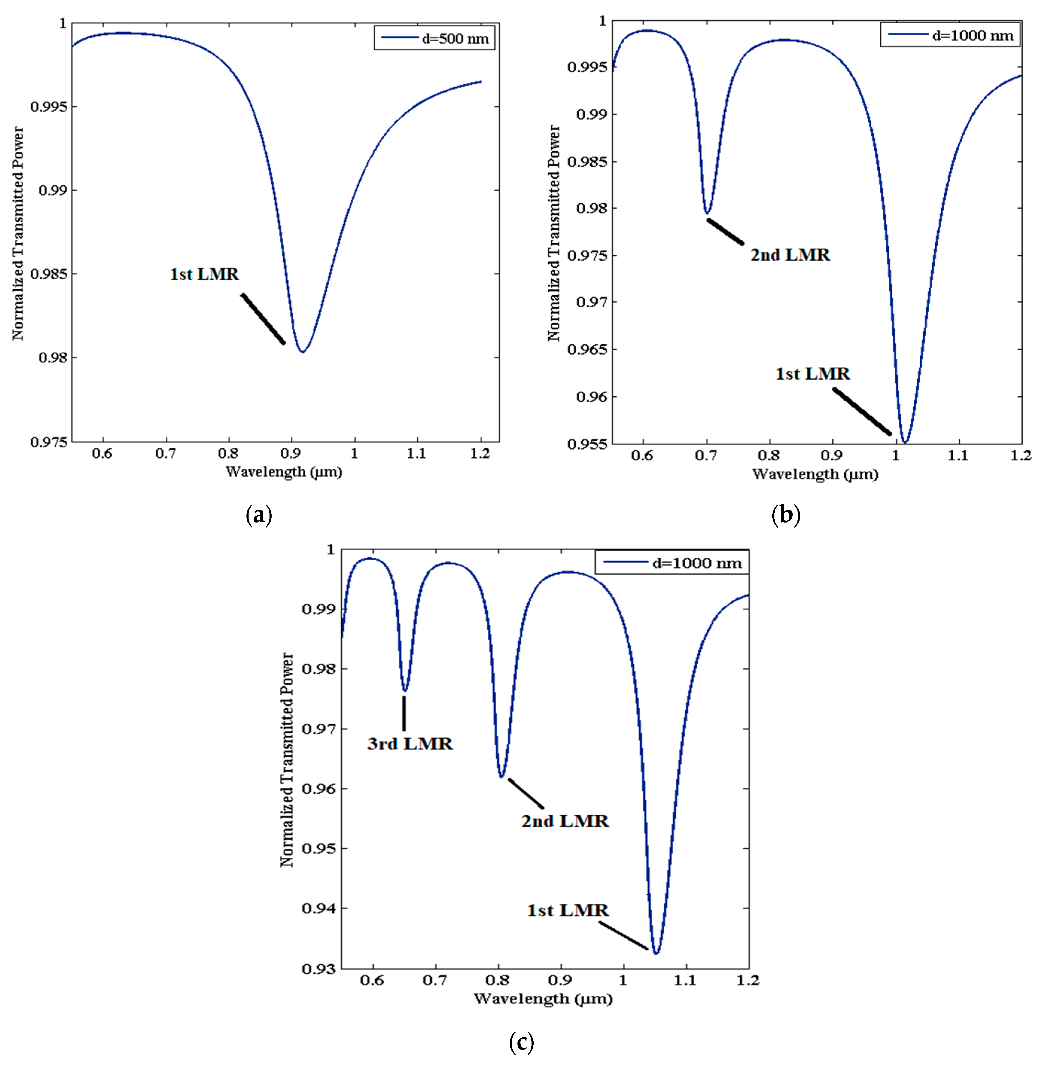
Figure 1. Transmission spectra of LMR-based FOS coated with AZO, having thicknesses of (a) 500 nm, (b) 1000 nm, and (c) 1500 nm. Other parameters that were used: SMRI = 1.333, length of sensing region = 0.5 cm, numerical aperture = 0.22, and core diameter = 600 µm.
2.2. Resemblances and Differences between SPR and LMR
It becomes necessary to identify the similarities and differences between the two kinds of resonances, i.e., SPR and LMR. Like SPR, LMR also depends on various parameters such as the SMRI, thickness, and dielectric permittivity of the coated film. Further, both techniques use the coating of thin films as a sensing layer to excite surface plasmon (SP) modes/lossy modes, and the substances or medium to be detected are placed around that coated film. Both these resonance techniques can work on the single sensing principle and utilize the Kretschmann–Raether configuration. Moreover, in both techniques, it is possible to use additional coating layers adhering to the resonance supporting layer for the detection of various sensing analytes [43]. Finally, the attenuation bands in the spectra are similar in both kinds of resonances, showing a sharp dip in intensity at the resonance parameter, and these resonance dips are highly sensitive towards any change in the SMRI. In terms of differences, the LMR technique supports a wide range of materials including the thin film of CMOs or polymers for the fabrication of a fiber optic sensing probe, whereas SPR needs the thin film of metals for the excitation of SPs. The CMOs are relatively economical, and researchers have easy access to them, which is also beneficial for the large-scale production of LMR-based FOSs. To achieve the SPR phenomenon, only transverse magnetic (TM)-polarized light is used, whereas in LMR both TM and transverse electric (TE)-polarized light can be considered, which substantially simplifies the experimental setup. In case of SPR technique, while launching light, the typical range of the incidence angle is 40° to 75°; however, LMRs are generated by launching the light at the grazing angle incidence, i.e., the angle approaching to 90° [62][63]. Thus, most experimental work on LMRs utilizes an optical fiber core instead of an optical prism because, in the latter case, it becomes very difficult to direct light at around 90° [64]. Further, a notable difference is that unlike SPR, which has only one resonance dip, the LMR spectrum produces multiple resonance dips and can be tuned by varying the thickness of the coated film too, without any modifications in the optical fiber geometry. This means that when a solo parameter is measured, the accuracy of the measurement can be guaranteed by obtaining information from multiple resonance dips, and, when multiple parameters are measured, one can obtain a different parameter’s information from the different resonance dips, which contribute to signal demodulation. This property makes the LMR technique more suitable for fabricating multi-peak sensors, with a higher sensitivity and better accuracy [64]. Apart from this, the resonance curves are broader and shallower in LMR-based FOSs than those in SPR-based FOSs, leading to a decrease in the resolution of the measurements and, hence, a decrease in the full width at half maximum (FWHM) and figure of merit (FOM) values. This may be because both TE- and TM-polarized light can generate LMR, i.e., LMRTE and LMRTM. However, due to the smaller value of the imaginary part of the thin-film RI, the LMRTE and LMRTM are located at different wavelengths, and the largest gap can reach several hundred nanometers. In addition, the resonance dips in the SPR technique are located in the visible region of the optical spectrum in general; however, the LMR dips lie in the visible or near-infrared (IR) regions. Currently, the information transmission of optical fibers lies in the near-IR region, favoring LMR-based FOSs.3. Materials Supporting Lossy Modes for Sensing Applications
Unlike SPR, the LMR phenomenon is supported by a wide range of LMR active materials including various metal oxides such as indium tin oxide (ITO), indium oxide (In2O3), zinc oxide (ZnO), tin oxide (SnO2), titanium oxide (TiO2), etc., and polymers as well. In recent years, the gas-sensing mechanism of metal oxides has been extensively investigated, and it is believed that the initial process is the diffusion of the analyte gas from the surrounding medium to the semiconducting metal oxide surface [65]. The second process involves a charge-transferring interaction between the analyte gas and the metal oxide surface. This depends on the gas adsorption, the change in charge-carrier concentration in propinquity to the oxide surface, and the surface reactions [66]. Lastly, the working temperature of the sensor plays a crucial role in the formation of reactive species and the chemisorbed reactive oxygen species’ role, either in the formation of reactive species or in the chemisorbed reactive oxygen species/ions, per the following reactions [67][68]:3.1. Indium Tin Oxide (ITO)
ITO is one of the most recognized CMOs, which has a wide range of applications in optics and electronics [69]. It is mainly a compound of indium oxide and tin oxide, having different composition ratios that affect their electrical and mechanical properties. ITO films are chemically stable in nature and, hence, can simply be coated over an optical fiber core via several deposition methods. The dispersion curve depicted in [44] confirms that ITO satisfies the generation condition of both SPR (at a higher wavelength, from 0.4–1.3 µm) and LMR (at a wavelength beyond 1.3 µm), as discussed above. Moreover, its conductivity increases further by increasing the thickness of ITO and, hence, results in a better sensitivity for the LMR sensor, which makes ITO a promising candidate in various sensing applications. Zamarreno et al. experimentally designed a FOS utilizing a thin film of ITO coated over a uniform fiber core in the IR region of the optical spectrum [38]. The ITO layer allowed the coupling of light from the optical waveguide layer to the ITO/sensing medium as a function of the SMRI. The study showed that a maximum sensitivity of 3125 nm/RIU is achievable, with the utilization of an ITO film that quickly senses the analyte. In another work, a LMR-based FOS was designed for the detection of thrombin, by utilizing an aptamer receptor [70]. The designed LMR sensor consisted of a novel aptamer–polymer structure fabricated over an ITO-coated optical fiber core employing the LbL electrostatic self-assembly method. The variation in the RI of thrombin, which acts as a sensing region, results in the wavelength shift of the LMR curves, and, hence, the designed configuration detected even low (100 nM) and very high (1 µM) concentrations of thrombin. The fabricated LMR device showed a better response time with a maximum shift of 3 nm in the RW. Another application of ITO-coated LMR-based FOSs was reported for the detection of relative humidity (RH) [71]. In that study, a thin coating of ITO was studied over a cladding-etched multimoded optical fiber, with a core diameter of 200 µm to sense the relative humidity. The sensor, designed with ITO, attained a sensitivity of 0.283 nm/%RH for RH detection, and this value was further enhanced to 0.833 nm/%RH by coating an addition layer of PAH–PAA over the ITO. In 2013, Corres et al. proposed a LMR-based tunable filter with the multilayer deposition of ITO/PVDF/ITO over a plastic-clad silica (PCS) multimoded optical fiber [72]. The initially used ITO layer generated the LMRs in the spectrum and also acted as a first electrode; the PVDF layer tuned the filter, and the second ITO layer allowed for the measurement of the variation in its RI as a function of the applied voltage, in order to attain a high sensitivity, i.e., 0.4 nm/V. In a similar study of electrochemical processes, an ITO layer was coated over the fiber core and was applied as a working electrode in a cyclic voltammetry setup [73]. The results concluded that any change in applied voltage corresponding to the ITO surface resulted in a substantial variation in the LMR response. Additionally, a fiber optic LMR sensor coated with ITO film can be considered as a dual-domain sensor, when operated with the optical and electrochemical processes [74]. Soon after this, an ITO-coated RI sensor based on LMR was designed, employing angular and wavelength interrogation techniques [75]. The authors reported the maximum value of sensitivity as 4652 nm/RIU, by inserting an additional low-index matching layer. In a similar study, it was shown that a particular thickness of ITO can generate both SPR and LMR in the wavelength range of 450 to 2000 nm, which can be further used in optical sensing [76][77][78][79][80][81]. Recently, a fiber optic LMR sensor coated with ITO thin film was used for the detection of hydrogen (H2) gas sensing [57].3.2. Indium Oxide (In2O3)
In2O3 is another CMO material that often displays transparency in the visible wavelength regime, which is mostly utilized in batteries, solar cells, and optical coatings [82]. In the early part of the 20th century, In2O3 was reported as being used for the detection of NO2 gas, with the chemisorption process over its surface having a concentration of up to 5 ppm [83]. The real and imaginary parts of the RI of In2O3 shows that In2O3 satisfied the condition of LMR in the plotted wavelength region [84]. The first application of In2O3 in LMR-based optical fiber refractometers was reported by Zamarreno et al., in 2010 [85]. The designed sensor showed a maximum RI sensitivity of 4068 nm/RIU, for a variation between 1.333–1.392 in the SMRI. In their another work, the authors presented the design considerations of a fiber optic LMR sensor utilizing an In2O3 film for both TM- and TE-polarized light, and the corresponding sensitivity values were 4255 nm/RIU and 4926 nm/RIU, respectively [39].3.3. Zinc Oxide (ZnO)
The next material that fulfils the generation condition of LMR is zinc oxide, or the compounds formed via doping in it. Zinc oxide belongs to the CMOs group, which has a better absorption band in the ultraviolet–visible region of the optical spectrum and, hence, turns out to be a promising material in optical applications [86]. Apart from this, it possesses various significant properties such as a high transparency, wide band gap, better thermal conductivity, and higher carrier mobility, which makes it a suitable material in the field of electronics and sensing [87][88]. The dispersion curves for ZnO confirm that it acts as a LMR active material in the visible region and satisfies the SPR condition in the near-IR region of the wavelength. The first LMR sensor that utilized ZnO as a transducing material was reported by Andreev et al., who observed a sensitivity value of 1700 nm/RIU for a variation between 1.333–1.450 in the SMRI [37]. However, the primary experimental investigation of a fiber optic LMR sensor utilizing ZnO as a thin LMR coating material was reported in 2015 [43]. The authors presented the fabrication and characterization techniques of fiber optic LMR sensors for hydrogen sulphide (H2S) gas detection. Fiber optic probes were fabricated by coating a thin film of ZnO and ZnO nanoparticles over an unclad portion of the fiber core. The ZnO layer used reacts with H2S, which resulted in the change of the dielectric constant of ZnO. To fabricate the fiber probe, a PCS multimode fiber with a core diameter 600 µm was used, and then a 12 nm ZnO film was coated over a cladding-etched uniform fiber core employing a thermal-evaporation-based vacuum coating unit. The fiber probe was then coated with ZnO nanoparticles by dipping it into solution of ZnO NPs. To realize the fabricated fiber probe as a LMR sensor, the experiments were performed with several concentrations (10–100 ppm) of H2S gas, and the corresponding LMR absorption spectra were recorded. The results showed that with an increase in H2S gas concentration, the absorbance and, hence, wavelength corresponding to the maximum absorbance increases. This is due to the modification in both the real and imaginary parts of permittivity, as well as the RI of ZnO when it comes in contact with H2S gas. The corresponding variation of the peak LMR wavelength with the H2S concentration revealed that the LMR wavelength shows a non-linear increment with an increase in the H2S concentration. Thus, it was concluded that the designed LMR sensor for H2S gas detection shows a better selectivity, and the same is verified by completing the experiment with different gases.References
- Arregui, F.J.; Matias, I.R.; Goicoechea, J.; Villar, I.D. Optical fiber sensors based on nanostructured coatings. In Sensors Based on Nanostructured Materials; Arregui, F.J., Ed.; Springer: Berlin, Heidelberg, 2009; pp. 275–301. ISBN 978-1-4419-4601-0.
- Matias, I.R.; Ikezawa, S.; Corres, J. Fiber Optic Sensors: Current Status and Future Possibilities, 1st ed.; Springer International Publishing: Cham, Switzerland, 2017.
- Wei, L.; Tjin, S.C. Special Issue “Fiber Optic Sensors and Applications: An Overview”. Sensors 2020, 20, 3400.
- Lee, B.; Roh, S.; Park, J. Current status of micro- and nano-structured optical fiber sensors. Opt. Fiber Technol. 2009, 15, 209–221.
- Cusano, A.; Lpez-Higuera, J.M.; Matias, I.R.; Culshaw, B. Editorial optical fiber sensor technology and applications. IEEE Sens. J. 2008, 8, 1052–1054.
- Lee, B. Review of the present status of optical fiber sensors. Opt. Fiber Technol. 2003, 9, 57–79.
- Udd, E.; Spillman, W.B., Jr. Fiber Optic Sensors: An Introduction for Engineers and Scientists; John Wiley & Sons: Hoboken, NJ, USA, 2011.
- Kim, S.; Lee, J.; Jeon, H.; Kim, H.J. Fiber-coupled surface-emitting photonic crystal band edge laser for biochemical sensor applications. Appl. Phys. Lett. 2009, 94, 13–133503.
- Ozcariz, A.; Zamarreno, C.R.; Arregui, F.J. A comprehensive review: Materials for the fabrication of optical fiber refractometers based on lossy mode resonance. Sensors 2020, 20, 1972.
- Wolfbeis, O.S. Fiber-optic chemical sensors and biosensors. Anal. Chem. 2006, 78, 3859–3874.
- Stewart, G.; Jin, W.; Culshaw, B. Prospects for fibre-optic evanescent-field gas sensors using absorption in the near-infrared. Sens. Act. B Chem. 1997, 38, 42–47.
- Chan, K.; Ito, H.; Inaba, H. An optical-fiber-based gas sensor for remote absorption measurement of low-level CH4 gas in the near-infrared region. Journal of Lightwave Tech. 1984, 2, 234–237.
- Wang, X.; Wolfbeis, O.S. Fiber-optic chemical sensors and biosensors (2015–2019). Anal. Chem. 2020, 92, 397–430.
- Holst, G.; Mizaikoff, B. Chapter: Fiber optic sensors for environmental applications. In Handbook of Optical Fiber Sensing Technology, 1st ed.; John Wiley & Sons: Hoboken, NJ, USA, 2002.
- Dietrich, A.M.; Jensen, J.N.; da Costa, W.F. Chemical species. Water Environ. Res. 1996, 68, 391–406.
- Schweizer, G.; Latka, I.; Lehmann, H.; Willsch, R. Optical sensing of hydrocarbons in air or in water using UV absorption in the evanescent field of fibers. Sens. Act. B Chem. 1997, 38, 150–153.
- Mizaikoff, B.; Taga, K.; Kellner, R. Infrared fiber optic gas sensor for chlorofluorohydrocarbons. Vib. Spectrosc. 1995, 8, 103–108.
- Joe, H.E.; Yun, H.; Jo, S.H.; Jun, M.B.G.; Min, B.K. A review on optical fiber sensors for environmental monitoring. Int. J. Precis. Eng. Manuf.-Green Tech. 2018, 5, 173–191.
- Rowe-Taitt, C.A.; Ligler, F.S. Fibre optic biosensors. In Handbook of Optical Fibre Sensing Technology; John Wiley & Sons: Hoboken, NJ, USA, 2001.
- Ferguson, J.A.; Boles, T.C.; Adams, C.P.; Walt, D.R. A fiber-optic DNA biosensor microarray for the analysis of gene expression. Nat. Biotechnol. 1996, 14, 1681–1684.
- Healy, B.G.; Li, L.; Walt, D.R. Multianalyte biosensors on optical imaging bundles. Biosens. Bioelectron. 1997, 12, 521–529.
- Barker, S.L.R.; Kopelman, R.; Meyer, T.E.; Cusanovich, M.A. Fiber-optic nitric oxide-selective biosensors and nanosensors. Anal. Chem. 1998, 70, 971–976.
- Kuzubasoglu, B.A.; Bahadir, S.K. Flexible temperature sensors: A review. Sens. Act. A Phys. 2020, 315, 112282.
- Ascorbe, J.; Corres, J.M.; Arregui, F.J.; Matias, I.R. Recent developments in fiber optics humidity sensors. Sensors 2017, 17, 893.
- Tan, J.Y.; Ng, S.M.; Stoddart, P.R.; Chua, H.S. Trends and Applications of U-Shaped Fiber Optic Sensors: A Review. IEEE Sens. J. 2020, 21, 120–131.
- Goicoechea, J.; Zamarreno, C.R.; Matias, I.R.; Arregui, F.J. Utilization of white light interferometry in pH sensing applications by mean of the fabrication of nanostructured cavities. Sens. Act. B Chem. 2009, 138, 613–618.
- Corres, J.M.; Matias, I.R.; Villar, I.D.; Arregui, F.J. Design of pH sensors in long-period fiber gratings using polymeric nanocoatings. IEEE Sens. J. 2007, 7, 455–463.
- Larrion, B.; Hernaez, M.; Arregui, F.J.; Goicoechea, J.; Bravo, J.; Matias, I.R. Photonic crystal fiber temperature sensor based on quantum dot nanocoatings. J. Sens. 2009, 2009, 932471.
- Polynkin, P.; Polynkin, A.; Peyghambarian, N.; Mansuripur, M. Evanescent field-based optical fiber sensing device for measuring the refractive index of liquids in microfluidic channels. Opt. Lett. 2005, 30, 1273–1275.
- Lee, B.H.; Kim, Y.H.; Park, K.S.; Eom, J.B.; Kim, M.J.; Rho, B.S.; Choi, H.Y. Interferometric fiber optic sensors. Sensors 2012, 12, 2467–2486.
- Marciniak, M.; Grzegorzewski, J.; Szustakowski, M. Analysis of lossy mode cut-off conditions in planar waveguides with semiconductor guiding layer. IEE Proc. J. (Optoelectron.) 1993, 140, 247–252.
- Yang, F.; Sambles, J.R. Determination of the optical permittivity and thickness of absorbing films using long range modes. J. Modern Opt. 1997, 44, 1155–1163.
- Batchman, T.E.; Mcwright, C.M. Mode coupling between dielectric and semiconductor planar waveguides. IEEE Trans. Microw. Theory Tech. 1982, 30, 628–634.
- Villar, I.D.; Zamarreño, C.R.; Hernaez, M.; Arregui, F.J.; Matias, I.R. Lossy mode resonance generation with indium-tin-oxide-coated optical fibers for sensing applications. J. Lightwave Technol. 2010, 28, 111–117.
- Corres, J.M.; Villar, I.D. Arregui, F.J.; Matias, I.R. Analysis of lossy mode resonances on thin-film coated cladding removed plastic fiber. Opt. Lett. 2015, 40, 4867–4870.
- Andreev, A.; Pantchev, B.; Danesh, P.; Zafirova, B.; Karakoleva, E.; Vlaikova, E.; Alipieva, E. A refractometer sensor using index-sensitive mode resonance between single-mode fiber and thin film amorphous silicon waveguide. Sens. Act. B Chem. 2005, 106, 484–488.
- Andreev, A.; Zafirova, B.S.; Karakoleva, E.; Dikovska, A.O.; Atanasov, P.A. Highly sensitive refractometers based on a side-polished single-mode fibre coupled with a metal oxide thin-film planar waveguide. J. Opt. A Pure Appl. Opt. 2008, 10, 035303.
- Zamarreno, C.R.; Hernaez, M.; Villar, I.D.; Matias, I.R.; Arregui, F.J. ITO coated optical fiber refractometers based on resonances in the infrared region. IEEE Sens. J. 2010, 10, 365–366.
- Zamarreno, C.R.; Sanchez, P.; Hernaez, M.; Villar, I.D.; Valdivielso, C.F.; Matias, I.R. Sensing properties of indium oxide coated optical fiber devices based on lossy mode resonances. IEEE Sens. J. 2012, 12, 151–155.
- Hernaez, M.; Villar, I.D.; Zamarreno, C.R.; Arregui, F.J.; Matias, I.R. Optical fiber refractometers based on lossy mode resonances supported by TiO2 coatings. Appl. Opt. 2010, 49, 3980–3985.
- Paliwal, N.; John, J. Sensitivity enhancement of aluminium doped zinc oxide (AZO) coated lossy mode resonance (LMR) fiber optic sensors using additional layer of oxides. In Frontiers in Optics; JTu3A-40; Optical Society of America: Tucson, AZ, USA, 2014.
- Sanchez, P.; Zamarreno, C.R.; Hernaez, M.; Matias, I.R.; Arregui, F.J. Optical fiber refractometers based on Lossy Mode Resonances by means of SnO2 sputtered coatings. Sens. Act. B Chem. 2014, 202, 154–159.
- Usha, S.P.; Mishra, S.K.; Gupta, B.D. Fiber optic hydrogen sulfide gas sensors utilizing ZnO thin film/ZnO nanoparticles: A comparison of surface plasmon resonance and lossy mode resonance. Sens. Act. B Chem. 2015, 218, 196–204.
- Paliwal, N.; John, J. Lossy mode resonance (LMR) based fiber optic sensors: A review. IEEE Sens. J. 2015, 15, 5361–5371.
- Korotcenkov, G. Metal oxides for solid-state gas sensors: What determine our choice. Mater. Sci. Eng. B 2007, 139, 1–23.
- Grundmann, M.; Frenzel, H.; Lajn, A.; Lorenz, M.; Schein, F.; Wenckstern, H.V. Transparent semiconducting oxides: Materials and devices. Phys. Status Solidi A 2010, 207, 1437–1449.
- Socorro, A.B.; Villar, I.D.; Corres, J.M.; Arregui, F.J.; Matías, I.R. Lossy mode resonance-based pH sensor using a tapered single mode optical fiber coated with a polymeric nanostructure. Sensors 2011, 238–241.
- Zubiate, P.; Zamarreno, C.R.; Villar, I.D.; Matias, I.R.; Arregui, F.J. Tunable optical fiber pH sensors based on TE and TM Lossy Mode Resonances (LMRs). Sens. Act. B Chem. 2016, 231, 484–490.
- Rivero, P.J.; Goicoechea, J.; Hernaez, M.; Socorro, A.B.; Matias, I.R.; Arregui, F.J. Optical fiber resonance-based pH sensors using gold nanoparticles into polymeric layer-by-layer coatings. Microsystem Tech. 2016, 22, 1821–1829.
- Gupta, B.D.; Usha, S.P.; Shrivastav, A.M. A.M. A novel approach of LMR/MIP for optical fiber based salivary cortisol sensor. In CLEO: Science and Innovations; JTu5A-145; Optical Society of America: San Jose, CA, USA, 2016.
- Usha, S.P.; Shrivastav, A.M.; Gupta, B.D. A contemporary approach for design and characterization of fiber-optic-cortisol sensor tailoring LMR and ZnO/PPY molecularly imprinted film. Biosens. Bioelectron. 2017, 87, 178–186.
- Usha, S.P.; Shrivastav, A.M.; Gupta, B.D. Silver nanoparticle noduled ZnO nanowedge fetched novel FO-LMR based H2O2 biosensor: A twin regime sensor for in-vivo applications and H2O2 generation analysis from polyphenolic daily devouring beverages. Sens. Act. B Chem. 2017, 241, 129–145.
- Zubiate, P.; Zamarreno, C.R.; Sanchez, P.; Matias, I.R.; Arregui, F.J. High sensitive and selective C-reactive protein detection by means of lossy mode resonance based optical fiber devices. Biosens. Bioelectron. 2016, 93, 176–181.
- Ascorbe, J.; Corres, J.M.; Arregui, F.J.; Matias, I.R. Optical fiber humidity sensor based on a tapered fiber asymmetrically coated with indium tin oxide. IEEE Sens. 2014, 1916–1919.
- Ascorbe, J.; Corres, J.M.; Matias, I.R.; Arregui, F.J. High sensitivity humidity sensor based on cladding-etched optical fiber and lossy mode resonances. Sens. Act. B Chem. 2016, 233, 7–16.
- Tien, C.L.; Mao, H.S.; Lin, H.Y.; Sun, W.S. Liquid salinity sensor based on D-shaped single mode fibers coated with In-Ga-Zn-O thin film. In Proc. of SPIE; International Society for Optics and Photonics: Bellingham, WAS, USA, 2016; Volume 10150.
- Mishra, S.K.; Usha, S.P.; Gupta, B.D. A lossy mode resonance-based fiber optic hydrogen gas sensor for room temperature using coatings of ITO thin film and nanoparticles. Meas. Sci. Technol. 2016, 27, 045103.
- Socorro, A.B.; Corres, J.M.; Villar, I.D.; Arregui, F.J.; Matias, I.R. Immunoglobulin G sensors by means of lossy mode resonances induced by a nanostructured polymeric thin-film deposited on a tapered optical fiber. In Proceedings of the Trends in Nano Technology Conference, Madrid, Spain, 10–14 September; 2012.
- Arregui, F.J.; Villar, I.D.; Corres, J.M.; Goicoechea, J.; Zamarreño, C.R.; Elosua, C.; Hernaez, M.; Rivero, P.J.; Socorro, A.B.; Urrutia, A.; et al. Fiber-optic lossy mode resonance sensors. Procedia Eng. 2014, 87, 3–8.
- Golant, E.I.; Golant, K.M. Fields and modes in thin film coated optical waveguides. In Proceedings of the 2019 PhotonIcs & Electromagnetics Research Symposium-Spring (PIERS-Spring), Rome, Italy, 17–20 June 2019; pp. 725–732.
- Golant, E.I.; Pashkovskii, A.B.; Golant, K.M. Lossy mode resonance in an etched-out optical fiber taper covered by a thin ITO layer. Appl. Opt. 2020, 59, 9254–9258.
- Torres, V.; Beruete, M.; Sánchez, P.; Villar, I.D. Indium tin oxide refractometer in the visible and near infrared via lossy mode and surface plasmon resonances with Kretschmann configuration. Appl. Phys. Lett. 2016, 108, 043507.
- Villar, I.D.; Torres, V.; Beruete, M. Experimental demonstration of lossy mode and surface plasmon resonance generation with Kretschmann configuration. Opt. Lett. 2015, 40, 4382–4739.
- Fuentes, O.; Villar, I.D.; Corres, J.M.; Matias, I.R. Lossy mode resonance sensors based on lateral light incidence in nanocoated planar waveguides. Sci. Rep. 2019, 9, 8882.
- Shankar, P.; Rayappan, J.B.B. Gas sensing applications of metal oxides—A review. Sci. Lett. J. 2015, 4, 126.
- Barsan, N.; Weimar, U. Conduction model of metal oxide gas sensor. J. Electroceramics 2001, 7, 143–167.
- Li, Z.; Li, H.; Wu, Z.; Wang, M.; Luo, J.; Torun, H.; Hu, P.; Yang, C.; Grundmann, M.; Liu, X.; et al. Advances in designs and mechanisms of semiconducting metal oxide nanostructures for high-precision gas sensor operated at room temperature. Mater. Horiz. 2018, 6, 470–506.
- Lin, T.; Lv, X.; Hu, Z.; Xu, A.; Feng, C. Semiconductor metal oxides as chemoresistive sensors for detecting volatile organic compounds. Sensors 2019, 19, 233.
- Chopra, K.L.; Das, S.R. Why thin film in solar cells? In Thin Film Solar Cells; Springer: Boston, MA, USA, 1983; pp. 1–18.
- Razquin, L.; Zamarreno, C.R.; Munoz, F.J.; Matias, I.R.; Arregui, F.J. Thrombin detection by means of an aptamer based sensitive coating fabricated onto LMR-based optical fiber refractometer. Sens. IEEE 2012, 1–4.
- Sanchez, P.; Zamarreno, C.R.; Hernaez, M.; Villar, I.D.; Valdivielso, C.F.; Matias, I.R.; Arregui, F.J. Lossy mode resonances toward the fabrication of optical fiber humidity sensors. Meas. Sci. Tech. 2011, 23, 014002.
- Corres, J.M.; Ascorbe, J.; Arregui, F.J.; Matias, I.R. Tunable electro-optic wavelength filter based on lossy-guided mode resonances. Opt. Express 2013, 21, 31668–31677.
- Smietana, M.; Sobaszek, M.; Michalak, B.; Niedziałkowski, P.; Białobrzeska, W.; Koba, M.; Sezemsky, P.; Stranak, V.; Karczewski, J.; Ossowski, T.; et al. Optical monitoring of electrochemical processes with ITO-based lossy-mode resonance optical fiber sensor applied as an electrode. J. Light. Tech. 2018, 36, 954–960.
- Niedziałkowski, P.; Białobrzeska, W.; Burnat, D.; Sezemsky, P.; Stranak, V.; Wulff, H.; Ossowski, T.; Bogdanowicz, R.; Koba, M.; Śmietana, M. Electrochemical performance of indium-tin-oxide-coated lossy-mode resonance optical fiber sensor. Sens. Act. B: Chem. 2019, 301, 127043.
- Kaur, D.; Sharma, V.K.; Kapoor, A. High sensitivity lossy mode resonance sensors. Sens. Act. B Chem. 2014, 198, 366–376.
- Del Villar, I.; Zamarreño, C.R.; Hernaez, M.; Sanchez, P.; Arregui, F.J.; Matias, I.R. Generation of surface plasmon resonance and lossy mode resonance by thermal treatment of ITO thin-films. Opt. Laser Tech. 2015, 69, 1–7.
- Mishra, A.K.; Mishra, S.K.; Gupta, B.D. SPR based fiber optic sensor for refractive index sensing with enhanced detection accuracy and figure of merit in visible region. Opt. Commun. 2015, 344, 86–91.
- Gaur, D.S.; Purohit, A.; Mishra, S.K.; Mishra, A.K. An Interplay between Lossy Mode Resonance and Surface Plasmon Resonance and Their Sensing Applications. Biosensors 2022, 12, 721.
- Satyendra, K.; Mishra Durgesh, C.; Tripathi Akhilesh, K. Mishra, Metallic Grating-Assisted Fiber Optic SPR Sensor with Extreme Sensitivity in IR Region. Plasmonics 2022, 17, 575–579.
- Mishra, S.K.; Mishra, A.K. ITO/Polymer matrix assisted surface plasmon resonance based fiber optic sensor. Results Opt. 2021, 5, 100173.
- Mishra, S.K.; Verma, R.K.; Mishra, A.K. Versatile Sensing Structure: GaP/Au/Graphene/Silicon. Photonics 2021, 58, 547.
- Zhang, D.; Li, C.; Liu, X.; Han, S.; Tang, T.; Zhou, C. Doping dependent NH3 sensing of indium oxide nanowires. Appl. Phys. Lett. 2003, 83, 1845–1847.
- Liess, M. Electric-field-induced migration of chemisorbed gas molecules on a sensitive film-a new chemical sensor. Thin Solid Film. 2002, 410, 183–187.
- Villar, I.D.; Zamarreño, C.R.; Sanchez, P.; Hernaez, M.; Valdivielso, C.F.; Arregui, F.J.; Matias, I.R. Generation of lossy mode resonances by deposition of high-refractive-index coatings on uncladded multimode optical fibers. J. Opt. 2010, 12, 095503.
- Zamarreño, C.R.; Sanchez, P.; Hernaez, M.; Villar, I.D.; Valdivielso, C.F.; Matias, I.R.; Arregui, F.J. Dual-peak resonance-based optical fiber refractometers. IEEE Photonics Tech. Lett. 2010, 22, 1778–1780.
- Rodnyi, P.A.; Khodyuk, I.V. Optical and luminescence properties of zinc oxide. Opt. Spect. 2011, 111, 776–785.
- Wang, Z.L. Zinc oxide nanostructures: Growth, properties and applications. J. Phys. Condens. Matter 2004, 16, R829.
- Usha, S.P.; Gupta, B.D. Semiconductor metal oxide/polymer based fiber optic lossy mode resonance sensors: A contemporary study. Opt. Fiber Tech. 2018, 45, 146–166.
More