Your browser does not fully support modern features. Please upgrade for a smoother experience.
Please note this is a comparison between Version 1 by Danilo D’Angela and Version 2 by Peter Tang.
Nonstructural elements (NEs) are generally defined as elements typically housed within buildings/facilities that are not part of the structural system. Nonstructural elements are often classified as architectural elements, mechanical/electrical/hydraulic systems, and building contents. Nonstructural elements are often associated with critical seismic risk, due to their high vulnerability and exposure to seismic actions, especially for critical facilities such as hospitals and nuclear plant facilities.
- seismic assessment
- nonstructural elements
- seismic qualification
- quasi-static testing
- shake table testing
- testing protocols
1. Introduction
Nonstructural elements (NEs) of a building consist of (building) elements/components and contents that are not included in the structural system of the facility. Nonstructural elements can be either single elements or distributed systems (e.g., networks). They are typically not intended to be load-bearing elements, and are often attached/connected to structural/building elements. Nonstructural elements can also be not connected to the structure/building and can be moved or relocated during their lifetime (e.g., furniture). The dynamic behavior of NEs is typically associated with high seismic risk, since NEs are often highly vulnerable and exposed to damage caused by seismic actions. The critical seismic response of NEs was highlighted by several recent earthquake events, e.g., the 2010 Darfield, 2011 Christchurch, and 2016 Kaikōura New Zealand earthquakes [1][2][3][1,2,3], the 2010 offshore Maule earthquake in Chile [4], the 2009 L’Aquila (Italy) earthquake [5], the 2012 Emilia (Italy) earthquake [6], the 2016 Central Italy earthquake [7], and the 2020 Petrinja (Croatia) earthquake [8]. In particular, these and other seismic events proved that damage to NEs can be significant even within buildings that exhibit minor or negligible structural damage, potentially resulting in major economic losses and casualties.
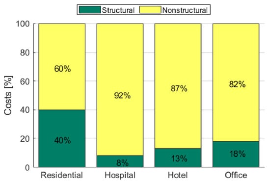
In most buildings, the biggest contributor to economic losses resulting from earthquakes is damage to NEs. In particular, they represent a large percentage of the total construction cost [9]. Figure 1 presents the cost distribution of four sample buildings including reinforced concrete (RC) residential buildings, hotels, office buildings, and hospitals, in the United States [9][10][9,10]. The cost of NEs is highest in hospitals, where approximately 92% of total construction costs are NEs; this number reduces to 87% for hotels, 82% for office buildings, and 60% for RC residential buildings. Furthermore, NEs are likely to exhibit moderate to severe damage even under relatively frequent earthquakes. Accordingly, the combination of major exposure and vulnerability makes NEs extremely critical in terms of seismic risk even over low to moderate seismicity areas.
Over the last twenty years, the research community has been investigating the seismic assessment of NEs, and copious amounts of the literature have been developed accordingly. As a result, the current European and international codes and standards (e.g., [11][12][13][14][15][16][11,12,13,14,15,16]) refer to the Performance-Based Earthquake Engineering (PBEE) approach and methods for the design and assessment of NEs. Significant attention has been recently focused on the estimation of (building) floor accelerations for the assessment of the seismic demands on NEs in buildings [17][18][19][20][21][22][23][17,18,19,20,21,22,23]. Existing codes establish rules and criteria for the seismic design and verification of NEs considering the effects of the earthquake in terms of forces (i.e., accelerations) and displacements (i.e., deformations). The dynamic proprieties of NEs should be typically known, in order to apply criteria and methods established by the codes and standards for the determination of seismic demand measures, whereas the seismic capacities of NEs should be estimated in order to carry out the design and assessment safety verifications. The evaluation of the seismic capacities shall be carried out via one of the following methods: (a) analysis, (b) (experimental) testing, (c) experience data, (d) a combination of methods (a), (b), and (c) [13][24][25][13,24,25]. The seismic assessment of NEs, aiming at producing robust standard capacity estimations and safety evaluations, is often referred to as seismic qualification and, in some cases, seismic certification [13][24][26][13,24,26].
Several analytical/numerical models have been developed in the literature for the seismic evaluation of NEs. However, each study is typically associated with a specific NE and is not generally extendable to different NE properties and characteristics [27][28][29][30][31][32][33][27,28,29,30,31,32,33]. Experimental testing is the most common method used to assess NEs, as this is typically considered to be the most reliable and robust option. Many research activities are focused on the seismic assessment/qualification of NEs by experimental tests, such as on plasterboard partition walls [34][35][36][37][38][39][40][41][42][43][44][34,35,36,37,38,39,40,41,42,43,44]; masonry infill walls [45][46][47][48][49][45,46,47,48,49]; innovative partition walls [50][51][52][53][50,51,52,53]; bracing systems for suspended ceilings [54] and suspended ceiling systems [55][56][57][58][59][60][55,56,57,58,59,60]; curtain walls [61][62][63][64][61,62,63,64]; technical equipment and systems: motor control centers (MCC) [65], cooling machines [66], riser pipe systems [67], hospital piping assemblies [68], pressurized fire sprinkler piping systems [69], medical gas and fire-protection pipeline joints [70]; hospital components [71][72][73][71,72,73]; museum artifacts and art objects [74][75][76][74,75,76], among many others. Seismic assessment and qualification through experience data might be theoretically more representative than other methods, since the NE response is estimated according to actual seismic events, but this is limited to specific characteristics of NEs, buildings, and seismic events. Regarding experimental test methods, testing protocols available in the literature generally vary depending on the type of NEs involved and the reference code. Finally, it is possible to develop hybrid methods to optimize the best characteristics of the single methods. Therefore, experimental testing is generally favored and considered to be more generally applicable and efficient, especially for critical and complex NEs.
2. Nonstructural Damage and Losses
Seismic events generally have four main effects on building NEs: (1) inertial or dynamic effects, (2) distortions imposed on NEs when the building structure deforms, (3) interaction at the interface between adjacent structures, and (4) interaction between adjacent NEs [77]. Seismic damage to NEs is associated with several parameters and features, including the dynamic properties of the NEs, NE location within the building (e.g., along height), NE vicinity to structures or other NEs, NE vicinity to structure anchorage or connection systems and properties. Nonstructural element damage may result in human losses and casualties, costly property damage to buildings and their contents, and functioning disruptions. In particular, the potential consequences of earthquake damage to NEs are typically divided into three types of risk referred to as the 3Ds: Deaths, Dollars, and Downtime [77]. The death type of risk is associated with the human losses caused by damage to or the response of NEs. Furthermore, life safety can also be affected in cases where damaged NEs obstruct safety pathways or exits [78]. Damage to life safety systems such as fire protection components or devices can also pose a safety concern in cases of fire after an earthquake or prior to fully restoring the system. Representative examples of critical and possibly hazardous NE damage include but are not limited to glass breaking, cabinets overturning, the collapse of ceilings and lighting system fixtures, the rupture of gas lines and other piping containing hazardous materials, damage to friable asbestos materials, the collapse of decorative molding parts, the failure of masonry infill walls, parapets, and chimneys (e.g., [9][79][9,79]). The property losses (Dollars) may be the result of direct damage to a NE or the consequences produced by its damage [77]. The loss can be associated with private or public properties and might be particularly critical (even priceless) in cases of damage to museums/historical monuments/facilities/objects or archives/storage facilities. For example, the 2016 Central Italy earthquake caused major damage to the stuccoes and decorations of monumental churches and historical palaces [7], and the 2009 L’Aquila earthquake caused damage and even destruction of historically valuable sculptures located in the Spanish Fortress (L’Aquila) and damage to furniture and artifacts in a church [1]. Several earthquake events have highlighted that the functioning of buildings can be typically disrupted by damage to NEs even though structural damage is not exhibited (e.g., they were designed according to modern codes). For example, severe damage to masonry infills and partitions was observed after the 2009 L’Aquila earthquake, involving many buildings that were designed and constructed not much earlier than the earthquake; this caused significant losses in terms of Downtime [5]. Post-earthquake downtime is highly critical when the building/facility function is considered vital, especially in the aftermath of the event, e.g., hospital and healthcare facilities, fire and police stations, manufacturing facilities, and government offices. Furthermore, downtime has a huge impact in situations where seismic and other emergencies/crises (e.g., sanitary emergencies) are combined. For instance, in 2020, in Croatia, the combination of the COVID-19 pandemic and two destructive earthquakes had an extremely critical impact on the population in terms of physical, economical, and social/psychological burden [8].3. Nonstructural Element (NE) Classifications
Nonstructural elements can be divided into three broad categories according to their service and function, namely: (1) architectural elements, such as infill and partition walls, curtain walls, ceiling systems, and architectural ornamentations; (2) mechanical, electrical, and plumbing elements for example pumps, chillers, fans, air-handling units, motor control centers, electrical cabinets, distribution panels, transformers, and piping; (3) furniture, fixtures and equipment, and contents such as shelving and bookcases, industrial storage racks, medical records, computer and desktop equipment, wall- and ceiling-mounted TVs and monitors, industrial chemicals and hazardous substances, historical and cultural objects [77]. Nonstructural elements are also generally classified in relation to one or more response parameters of the structure, namely engineering demand parameters (EDPs), and the related damage sensitivity of NEs [9]. Seismic actions potentially cause damage to (building) NEs according to four main modalities, as depicted in Figure 2: (a) inertial or shaking effects, causing component motion/oscillation, sliding, rocking or overturning; (b) building deformations, damaging interconnected NEs; (c) building separations damaging NEs at the seismic building joints due to differential displacements or at the boundaries of the facility; (d) interaction between adjacent NEs having relative displacement/response [77]. According to the above-mentioned classification, NEs can be grouped into three classes: (a) force-sensitive or acceleration-sensitive NEs, where inertial forces or accelerations can be considered as main EDPs, (b) displacement-sensitive or interstory-drift-sensitive NEs, where relative displacements/deformations can be assumed as main EDPs, (c) combined force/displacement-sensitive NEs, where both inertial forces/acceleration and relative displacements/deformations can be considered as main EDPs. There might be cases in which NEs are particularly sensitive to alternative or additional EDPs, such as velocity, as can be observed with regard to rocking-dominated NEs [80]; therefore, these classifications represent the basic reference and might not be exhaustive over the wide range of NE scenarios, especially for components that exhibit complex seismic response, with regard to multiple response and damage mechanisms.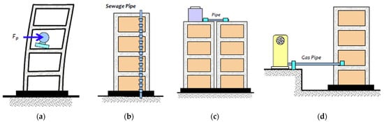
Figure 2. Effects of seismic motion on NEs: (a) inertial, (b) imposed deformations by building, (c) building separations, and (d) elements outside connected to the inside of the building [81].
4. Testing Protocols
4.1. Outline
Seismic tests are typically classified as quasi-static or dynamic according to the testing procedure and protocol. Single-floor dynamic tests define the traditional and most common dynamic tests, which are often carried out by means of shake tables. More recently, multi-floor dynamic testing has been developed to replicate the actual seismic demands on NEs in a more accurate manner; in particular, this novel testing approach takes into account the response of the hosting buildings/facilities (in terms of both acceleration and deformation inputs) for the more representative and consistent seismic testing of NEs.4.2. Quasi-Static Testing Protocols
Quasi-static tests are often performed to test displacement-sensitive NEs, or more generally, to test NEs that are sensitive to deformations. Nonstructural elements that can be tested according to this protocol include but are not limited to infill/cladding/partition panels (along their in-plane directions), piping and electrical network systems, fixed ladder systems, technical equipment fixed to multiple stories, and other systems that are connected to multiple building parts that might exhibit relative displacement under earthquake actions. Quasi-static tests are typically carried out by implementing cyclic loading procedures, i.e., slow load/deformation cycles, which can be conducted in force or deformation control. Overall, it is preferred to adopt a deformation-controlled testing protocol, except when forces govern the response of the NE or the deformation parameter is difficult to control. Quasi-static protocols should not be considered for NEs whose behavior is significantly conditioned by dynamic effects or is velocity-sensitive, including strain–rate-sensitive NEs. An example of the application of a quasi-static testing protocol is described in Pali et al. [37]. In this study, the authors designed a specific test setup for performing the in-plane cyclic tests on full-scale wall configurations according to the testing protocol. The test setup was built and assembled at the Test Laboratory of the Department of Structures for Engineering and Architecture at the University of Naples “Federico II”, and a schematic of the testing arrangement/setup and instrumentation is depicted in Figure 3. The test setup was a bidimensional frame made of S350JR steel-grade hot-rolled steel profiles, which reproduced the behavior of a typical story of a building structure. It was made of a bottom beam, a top beam, and 2 hinged columns. In particular, the bottom beam was fixed to the laboratory floor, whereas the top beam was connected to the hydraulic loading actuator by means of a sliding hinge used for avoiding vertical load components. The loading actuator had a stroke of 500 mm and a load capacity of 500 kN. The bottom and top beams were connected to each other by means of 2 vertical columns having rectangular hollow sections. The connections between columns and beams were uniaxial hinges with axes of rotation perpendicular to the plane of the testing frame. The out-of-plane displacements of the testing frame were avoided by 2 steel portal frames, having HEA140 vertical profiles equipped with roller wheels that allowed the top beam of the testing frame to slide in its plane. Therefore, the testing frame had negligible lateral in-plane stiffness. The indoor partition wall was infilled in the testing frame in such a way that it was surrounded along its perimeter by the top beam, bottom beam, and columns. Moreover, the setup was designed to allow the interposing of C25/30 strength-class 50 mm thick concrete blocks between specimens and testing frame, in such a way as to simulate the connections with a reinforced concrete building structure. In particular, concrete blocks were placed on the faces of beams (horizontal connections) and columns (vertical connections) of the testing frame facing the indoor partition wall.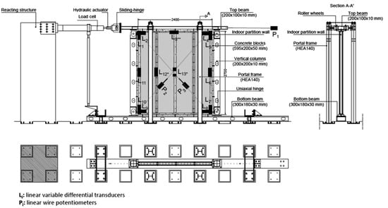
4.3. Single-Floor Dynamic Testing Protocols
Single-floor dynamic tests are frequently performed to test acceleration-sensitive NEs. Examples of NEs that may be tested in accordance with this protocol include cabinets, storage racks, bookcases and shelves, appliances (refrigerators, washing machines, diesel generators), hoardings anchored on rooftops, antennas (communication towers on rooftops), horizontal projections (sunshades, canopies, and marquees), storage vessels, mechanical equipment (boilers and furnaces, HVAC equipment), hospital cabinets, and museum artifacts. Single-floor dynamic tests are generally performed through a shake table or earthquake simulator, which is usually characterized by one or more degrees of freedom (translational and rotational). Tests are conducted by assigning input signals to the earthquake simulator, which depending on different protocols may be generated differently (artificial or real earthquakes). Earthquake simulators often have performance limitations in terms of acceleration, velocity, displacement, and frequency range, so the assigned input signals must be adjusted/modified to be compatible with these limitations. However, the input signals must meet the spectral compatibility conditions required by the testing protocols. An example of the application of a single-floor dynamic testing protocol is described in Truong et al. [82][85]. In this paper, the authors carried out shaking table tests for seismic performance evaluation of a base-isolated Uninterruptible Power Supply (UPS). The tests were performed according to the protocol described later. Figure 4 presents the shaking table test setup for the UPS test specimen. The shake table used for the triaxial test has the following primary characteristics: 4.0 × 4.0 m plan dimensions, six degrees of freedom, a maximum payload of 300 kN, peak accelerations of 1.5, 1.5, and 1.0 g in the X, Y, and Z directions, respectively, for the maximum payload, and a maximum overturning moment of 1200 kNm. The shake table reproduces earthquake input ground motions through a system of eight hydraulic actuators. The UPS test specimen was anchored to an RC slab using pins or through isolator systems with anchor bolts. The concrete slab was connected to the shaking table using anchor bolts.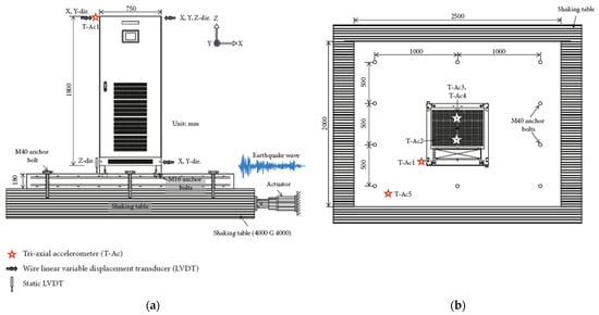
Figure 4.
Typical shaking table test setup: (
a
) front view and (
4.4. Multi-Floor Dynamic Testing Protocols
Until recently, testing facilities could not easily implement accurate full-scale testing on NEs by means of simultaneous floor acceleration and story deformation loading conditions, reproducing the actual arrangement of NEs housed within multistory buildings and sensitive to both accelerations and displacements (e.g., partition walls, cladding curtain walls, distributed duct, piping, electrical systems, Heating, Ventilation and Air Conditioning (HVAC) systems, suspended ceilings, and ceiling-mounted equipment).
A brilliant solution, as already discussed here, was found in [44][45][51][83][44,45,51,87], where the multi-floor dynamic testing was carried out by means of a test frame fixed to the shake table that simulated the seismic behavior of a generic story of a building, in which the NEs (i.e., partitions) were installed. The testing setup implemented by Magliulo et al. [44] is depicted in Figure 5. The test frame was designed in order to have an assigned drift, i.e., an assigned peak displacement of the top floor, and given a peak acceleration at the bottom floor, i.e., at the shake table. The geometry of the test frame was defined taking into account three requirements: (i) realistic value of mass; (ii) realistic interstory height h, assumed equal to 2.74 m; (iii) realistic interstory displacement dr, assumed equal to 0.005 h for a Damage Limit State (DLS) earthquake with 50-year return period. This strategy allows the assigning at the bottom floor of a time history according to single-floor dynamic testing protocols, e.g., AC156.
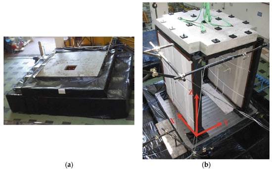
Figure 5.
Test setup for multi-floor dynamic testing according to Magliulo et al.: (
a
) shake table test and (
b
) test frame [44].
A different solution was found by the University at Buffalo, which commissioned a dedicated Nonstructural Component Simulator (UB-NCS) composed of a two-level testing frame capable of simultaneously subjecting NEs sensitive to both accelerations and displacements to realistic full-scale floor motions expected within multistory buildings also applying story deformation loading conditions. The relevant international reference testing and qualification protocol was developed by Retamales et al. [84][94]; a representative testing setup is shown in Figure 6 [84][94]. The protocol reduces the minimum testing frequency that can be considered in an experiment from 1.3 Hz, as in the current AC156 procedure, to 0.2 Hz, allowing for more realistic testing of NEs sensitive to low-frequency excitations (e.g., tall slender cantilever-type equipment, base-isolated equipment, etc.). The objective of this protocol is not to replace current testing protocols, but rather to enhance the capabilities and the type of equipment that can be tested. Unlike other testing protocols, this protocol is presented as a set of closed-form expressions defining a pair of displacement histories for the bottom and top levels of the UB-NCS that simultaneously matches: (i) a target acceleration response spectrum (either ground or floor response spectra), and (ii) a target-generalized interstory drift. Both the target spectral accelerations and drifts can be specified based on the expected values at a given normalized building height h/H, where h is the NE installation height above grade and H is the total building height. This qualification testing protocol considers as variables: (i) the location of the NEs along the height of the building through the parameter h/H; (ii) the range of frequencies to be assessed during testing (fmin–fmax); and (iii) the ASCE 7-16 design spectral response in the short period range, SDS
, and corresponding to 1 s period, SD1. The frequency content targeted for the seismic qualification testing protocol covers the range of frequencies between fmin = 0.2 Hz and fmax = 5 Hz. This range corresponds to the operating frequencies of the UB-NCS and the expected fundamental periods of typical multistory buildings, including some higher vibration modes.
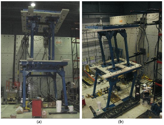
Figure 6.
Test setup for multi-floor dynamic testing according to Retamales et al.: (
a
) front view and (
) isometric view [94].
5. Novel Perspectives toward a Unified Testing Approach
5.1. Criticalities of Existing Protocols
The test protocols reviewed here are widely used in the literature, especially AC156 and FEMA 461. The AC156, FEMA 461 and ISO 13033 protocols were developed to assess and/or qualify the seismic performance of generic elements, and, among them, the AC156 protocol is the only one explicitly aimed at seismic certification. However, few recent research studies have pointed out potential criticalities of the AC156 protocol, in terms of both spectral demands (RRS) [66][85][86][87][66,95,96,97] and damage severity (e.g., for peculiar applications) [88][98]. The other protocols are intended for systems that are housed within critical facilities (i.e., telecommunications, electrical and nuclear systems) and provide a more standardized qualification approach, e.g., regarding the target performance levels or the seismic zones. Most protocols do not clearly define the applicability conditions with regard to the damage and response sensitivity of NEs. Overall, the aim of the reference protocols is often to assess whether the tested element, subject to a target seismic event (i.e., artificial or natural earthquake), meets certain functionality or stability requirements, i.e., pass or fail qualification outcomes. This criterion can be appropriate when the site and the element/building properties are known, which is peculiar to specific NEs (e.g., critical electric equipment for power stations). In different conditions, such as the generic qualification of NEs by the manufacturers, this approach cannot be easily applied, and the seismic evaluation of the element cannot be generalized.
5.2. Potential Improvement Interventions
Current regulations and codes often require the seismic design and safety verification of NEs. For this purpose, test protocols should include criteria and rules for the estimation of the dynamic properties (DPs) and the significant performance parameters (s) of the NEs to be tested. Dynamic properties are mostly required for a relatively accurate evaluation of the seismic demand, in compliance with the regulations/codes (e.g., [11][89][11,99]); DPs generally include the fundamental period ( Ta), the damping ratio ( ξa), and the (acceleration) amplification factor (ap) of the NE.
Significant performance parameters represent the quantitative parameters, or measures, to be considered for assessing seismic demands on and capacity of NEs and to verify the safety conditions. The SPPs can be considered to be efficient and applicable EDPs, with regard to the specific applications and testing procedures. As was discussed in the previous sections, these parameters depend on (a) the response and damage sensitivity of NEs to seismic actions, including site, building, and relevant interaction responses, and (b) the possibility of robustly assessing them through consolidated experimental testing procedures. The SPPs can be selected among inertial or deformation measures, or by the combination of them, according to the response/damage mechanisms of interest of the NEs to be tested. Accordingly, both seismic capacity and demand should be estimated considering consistent SPPs. The experimental testing procedures reviewed here can be used to assess the seismic capacities. The relevant codes/regulations typically define approaches and formulations for defining the seismic demand, which may also depend on the dynamic properties of both buildings and NEs, as was discussed in the previous sections.
For acceleration-sensitive NEs, the seismic capacity can be expressed in terms of peak floor acceleration (PFA) or peak component acceleration (PCA). The PFA is the maximum acceleration obtained on the floor on which the element was installed, while PCA is the maximum acceleration recorded on the component (e.g., in the element’s center of mass during the tests). For displacement- or deformation-sensitive elements, the seismic capacity can be expressed in terms of interstory drift ratio (IDR) or target displacement or deformation measures (δ), depending on the applied NE deformations that are relevant to the damage. Finally, for NEs that are sensitive to both acceleration- and deformation-based measures, both types of SPPs should be considered, also accounting for the relevant damage response/mechanisms.
5.3. Technical Recommendations and Final Remarks
Technical recommendations are developed for implementing a unified approach for seismic assessment of NEs by means of experimental tests, including seismic qualification purposes. These recommendations were defined in light of the critical review and assessment of current methods and protocols, according to the evidence pointed out in the previous sections. The technical recommendations and innovative perspectives derived here aim at improving the seismic assessment and qualification of NEs by means of experimental testing and represent an original literature and practice contribution.
Table 1 summarizes these recommendations. In particular, the key parameters/features associated with the seismic assessment, qualification, and safety verification of NEs are specified for the most common and representative NEs. The key parameters/features consist of response/damage sensitivity, SPPs, DPs, and recommended test types. No other studies have provided a critical review assessment and technical-scientific guidance regarding these applicative aspects, which are essential for implementing relatively reliable and robust assessment and qualification procedures. Table 1 represents a reference for both researchers and practitioners, and it might be implemented by codes and regulations.
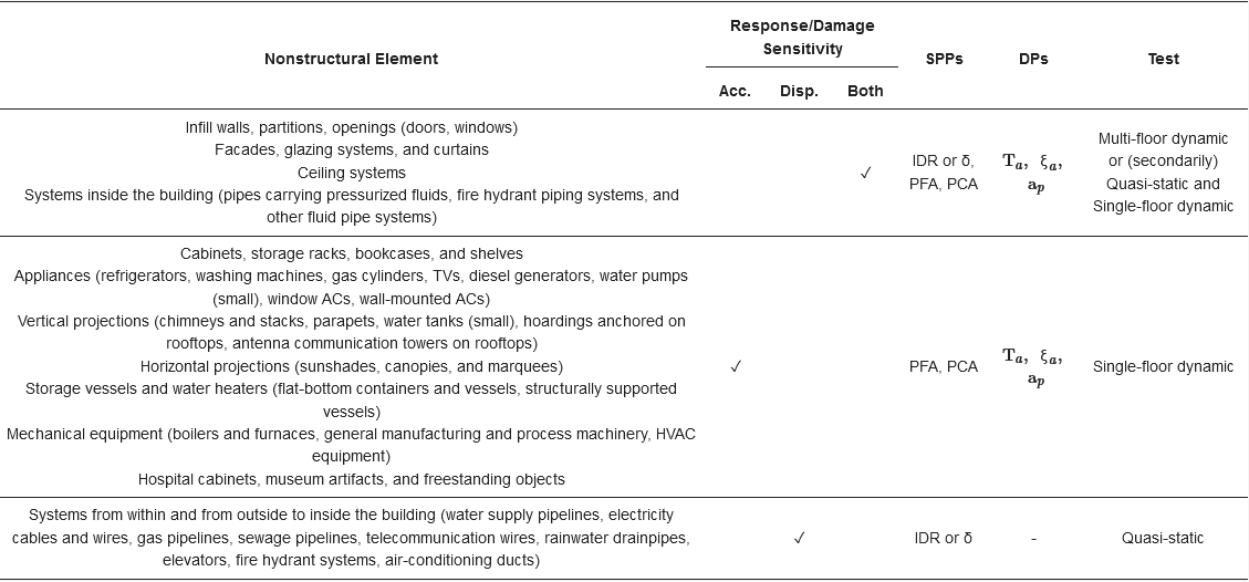
Table 1.
Recommended test protocol and DPs and SPPs required for the tested element.
When multi-floor dynamic tests cannot be performed, quasi-static and single-floor dynamic tests can be conducted separately. An example is the testing procedure adopted by Coppola et al. [90][100] by means of a special testing facility at the Components and Building Systems Laboratory of the Construction Technologies Institute of the National Research Council of Italy (ITC-CNR) in San Giuliano Milanese (Italy). Specifically, the authors conducted quasi-static and dynamic tests for the seismic evaluation of an innovative cladding system. The facility is able to accommodate full-size plane elements (partition systems, infill systems, façade systems, etc.), up to 6.3 m wide and up to 8.0 m high. The components can be anchored to the steel supporting frame by means of three beams: one fixed beam at the bottom and two moving beams at the second and third levels. The intermediate and superior beams can be moved, in the plane and out of the plane direction, through six hydraulic actuators, to simulate seismic actions. A mechanical lift system for the moving beams allows for various interstory heights. The moving beams are supported on low-friction rollers and connected to a dynamically controlled hydraulic actuator system. The load cell and transducer of the hydraulic actuator relate to an advanced digital controller that enables the acquisition of real-time load and displacement data.
The testing procedure adopted by Coppola et al. [90][100], consists of cyclic quasi-static tests, performed along the in-plane direction according to the loading procedure proposed by FEMA 461, and incremental dynamic tests performed according to AC156.
A unified approach should not be limited to the robust selection of the key parameters and testing approaches/protocols, which already signifies a novel and crucial step in the field. In fact, the selected testing protocols should be applied by maximizing the testing outcomes in terms of systematicity and comprehensiveness. In other words, once the protocol is defined, the testing procedure and program should be implemented in order to identify and characterize the seismic response and damage of the tested NEs in a systematic and comprehensive manner. For example, (a) the dynamic properties of the specimen should be estimated corresponding to all relevant DSs, providing useful information regarding the influence of DSs on the dynamic properties, and (b) all relevant DSs, from operativity to ultimate/failure conditions, should be associated with thresholds of SPPs (NE capacity thresholds). However, these experimental correlations should be established by means of standardized approaches, which would allow fully consistent comparisons/extensions and, potentially, generalization. Even though few protocols include directions for implementing a more general and systematic approach, no systematic and standardized recommendations are generally provided. Moreover, most protocols still recommend a pass or fail assessment/qualification approach, which represents a limited application of the potentiality of the above-mentioned approach. Therefore, further studies should address the above-mentioned issue, by providing a unified approach in terms of testing procedure application and the systematicity and comprehensiveness of the experimental assessment and qualification of NEs.