Your browser does not fully support modern features. Please upgrade for a smoother experience.
Please note this is a comparison between Version 1 by De'an Wang and Version 1 by De'an Wang.
磁耦合谐振式无线电力传输(MCR-WPT)系统因其发射功率大、传输效率高、传输距离可接受等优点,被认为是最有前途的无线电力传输(WPT)方法。为了实现磁集中,通常将磁性材料制成的磁芯添加到MCR-WPT系统中,以提高耦合性能。
- wireless power transfer
- magnetic coupler
- magnetic material
1. Introduction
Wireless power transfer (WPT) technology has developed rapidly in recent years because of its unique advantages over traditional cable power supply methods [1,2,3,4,5]. It can significantly improve the reliability, convenience, and safety of the electric energy supply and solve the problems of sparks and maintenance difficulties caused by traditional plug-in power transmission modes [6,7,8]. WPT technology has broad application prospects in low-power scenarios such as mobile phones [9,10], wearable devices [11,12], implantable medical care [13,14,15], and smart home products [16,17], as well as high-power fields such as electric vehicles (EVs) [18,19,20,21,22,23], unmanned aerial vehicles (UAVs) [24,25], unmanned underwater vehicles (UUVs) [26,27,28], electric ships [29] and aerospace equipment [30,31]. There is no doubt that WPT technology eliminates the problem of insulation and wire wear due to contact friction and significantly improves the safety and reliability of charging systems.
Generally, the magnetic coupling resonant wireless power transfer (MCR-WPT) technology is considered the most promising WPT method for its major transmission power, high transmission efficiency, and long transmission distance [32,33,34]. The working principle of the MCR-WPT is to generate an alternating current from a high-frequency inverter power supply and pass it into the transmitting coil to generate an alternating high-frequency magnetic field in the space around the transmitting coil. The high-frequency magnetic field passes through the receiving coil and forms the high-frequency induction current. Then, the current through the secondary energy conversion links (rectifier and filter), provides stable electric energy to the load. MCR-WPT technology can be applied to power transmission of W ~ kW level and adapted to a wide range of applications. Since both the primary and secondary sides of the coupling coil use a tuning circuit to make it work in the resonance state of the same frequency, the energy exchange efficiency is very high. In addition, the electric vehicle wireless power transfer (EV-WPT) international standard SAE-J2954 [35] was proposed and adopted, which recommended using the magnetic coupling resonant method for wireless charging of EVs.
As an essential component of the MCR-WPT system for energy conversion and transmission, the magnetic coupler (MC) can be regarded as a non-contact loose coupling transformer composed of coil winding and magnetic core [36]. The coil winding is the key to realizing magnetic coupling, while the magnetic core made of soft magnetic materials is often overlooked. Generally, for a complete MC, including the primary and secondary sides, the coil winding realizes the construction of the space electromagnetic field based on Faraday’s electromagnetic induction law, and the magnetic material realizes the reshaping, restriction, and guidance of the space magnetic path. This is due to the remarkable permeability of magnetic materials compared with air medium, and most of the flux lines generated by coils will pass through the magnetic path with magnetic cores. Therefore, high-performance soft magnetic materials are recommended to be added to the magnetic coupler structure as a magnetic core, which significantly effects the improvement of coupling performance and electromagnetic shielding [37,38,39]. On the one hand, magnetic materials can effectively improve the quality factor and mutual inductance coupling coefficient, which plays a vital role in enhancing the system’s power level and transmission efficiency. On the other hand, magnetic materials can effectively decrease the electromagnetic leakage of magnetic couplers and reduce the electromagnetic radiation to electronic equipment of the system and surrounding environment, which is conducive to the realization of the electromagnetic compatibility (EMC) design.
However, from a negative perspective, WPT systems generally work in the higher frequency region of magnetic materials, bringing additional power loss. In addition, the use of magnetic cores increases the volume, weight, and cost of the system. WPT is a new field of magnetic materials with special needs and concerns different from the traditional application scenarios of magnetic materials (such as transformers and motors). As far as the research progress of magnetic materials for WPT is concerned, it is still in the stage of how to make good use of basic soft magnetic materials. Few magnetic material companies have proposed special magnetic materials specially designed and developed for WPT.
Nevertheless, with the deepening of the research on WPT technology, the contradiction between the requirements of high efficiency, high power density, low cost, lightweight, and the shortcomings of current WPT magnetic materials have gradually been exposed. The existing traditional magnetic materials will be challenging to adapt to the high-transmission performance requirements of the WPT system and may become a bottleneck restricting the further development of WPT technology. In brief, from the perspective of the current development heat of WPT technology in the field of consumer electronics and the promotion of EVs, the research on magnetic materials and magnetic structures of magnetic couplers in WPT systems will become a research hotspot in the future. It is also one of the critical ways to further break through the bottleneck problems mentioned above.
2. History, Theory and Applications of WPT
2.1. Brief History of WPT
The turning point of the first realization of electric energy transmission from wire to wireless can be traced back to the last century: Hertz provided conclusive evidence of the existence of electromagnetic waves, and Nicola Tesla successfully lit the phosphorescent lamp with his Tesla coil [40,41,42]. However, embodiments thereof involve an unnecessarily large electric field. Until 1964, the microwave radiation type wireless charging system was first proposed and applied to supplement energy for a special helicopter [43]. Although microwave radiation is very suitable for transmitting information, it will cause a lot of energy loss due to the divergent radiation space when transmitting power, and the power transmission efficiency is very low. Since then, electromagnetic induction radio energy transmission based on Faraday’s electromagnetic induction law has become a new research direction [44,45,46,47,48] and has continued into the 21st century. On this basis, the research institute has made many research achievements in lightweight, high-power capacity and density, and high misalignment tolerance WPT systems [49,50,51,52,53,54,55,56]. It is difficult not to highlight some of these landmark achievements. In 1976, the concept of dynamic radio energy transmission was first introduced [57], and LBNL evaluated its system feasibility. Dynamic wireless power transfer (DWPT) realizes the energy supply during the operation of EVs and the unlimited mileage endurance of EVs under ideal conditions. In 2007, Marin Soljačić [58] from Massachusetts Institute of Technology (MIT) proposed a mid-range MCR-WPT system, which acted as a leading role in academia. In 2009, Korea Advanced Institute of Science and Technology (KAIST) developed the first on-line electric vehicle (OLEV) prototype [59]. In the following years, KAIST rapidly commercialized and updated its OLEV products [60,61,62,63], which was named as one of the top 50 inventions in the world by Time magazine.2.2. Classification, Principle, and Comparison of WPT
The WPT technology can be realized based on different physical principles. The development of WPT technology is advancing in two major directions, near-field and far-field transmission, based on the distance of power transfer. Then, according to the power accumulation medium and transfer technique, the WPT technology is mainly divided into three types: electromagnetic induction type, electrostatic induction type, and electromagnetic radiation type [64,65,66]. The classification of WPT is shown in Figure 1. Moreover, WPT technology can be further divided into five categories: magnetic coupling resonant WPT (MCR-WPT), electric coupling WPT (EC-WPT), microwave WPT (MW-WPT), ultrasonic wireless power transfer (US-WPT), and optical wireless power transfer (OWPT). The operating frequency range, power range and applicable transmission distance of several WPT types can be visualized and specifically obtained from Figure 2 and Table 1.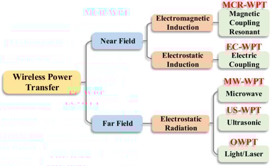
Figure 1. Classification of wireless power transfer technologies.
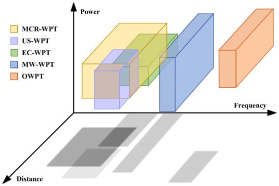
Figure 2. The performance of different types of wireless power transfer technologies in terms of power, frequency and distance.
Table 1. Ability Comparison of different WPT technologies.
| WPT Technologies | Power Range | Frequency Range | Transmission Distance | Transmission Efficiency | |
|---|---|---|---|---|---|
| Far Field | US-WPT | 0.1 mW~10 W | 50 kHz~5 MHz | 1 mm~5 m | <20% |
2.2.3. EC-WPT
The EC-WPT is usually referred to as capacitive power transfer (CPT), which usually uses two pairs of metal plates form an equivalent capacitor to transmit power. The system composition and basic principle of EC-WPT are shown in Figure 5. Due to its unique operating principle, EC-WPT can be used in applications requiring power transfer through metal materials [75]. Unlike the MCR-WPT system, the EC-WPT system transfers energy by the electric field, so it is unnecessary to carry a large number of magnetic cores. Thus, the EC-WPT system has a simple structure with no magnetic hysteresis loss. Furthermore, the main advantage of EC is that almost no electric flux can escape beyond the dielectric material, thus eliminating the problem of electromagnetic field exposure [76]. Due to the limitation of high resonant voltage, EC-WPT is usually designed as a system with high operating frequency and low power level [77,78].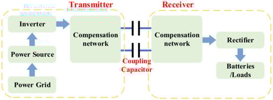
Figure 5. Components and fundamentals of the EC-WPT system.
2.2.4. MCR-WPT
MCR-WPT is now the most widely accepted and applied WPT method. In the MC-WPT system, the receiving coil picks up the flux lines of the magnetic field generated by the high-frequency current in the transmitting coil and converts it into a DC current for charging. The components and fundamentals of MCR-WPT are shown in Figure 6. The magnetic coupler can be regarded as a loosely coupled transformer with a long distance between the primary and secondary windings [83]. The loosely coupled transformer commonly has a large airgap between the double side windings, which leads to a lower coupling coefficient and higher electromagnetic leakage. Through the utilization of the magnetic core, the quality factor of coupling coils can be optimized, and then the effective power transfer can be realized [84].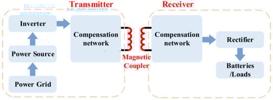
Figure 6. Components and fundamentals of the MCR-WPT system.
Table 2. Comparison of the main advantages and potential shortcomings of different WPT types.
| WPT Technologies | Main Advantages | Potential Shortcomings | |
|---|---|---|---|
| Institute | Year | Frequency (kHz) | Gap (cm) | Power Level (kW) | Efficiency | |||
|---|---|---|---|---|---|---|---|---|
| Parameters | 3C90 | 3C91 | 3C92 | 3C93 | 3C94 | 3C95 | 3C96 | 3C97 |
| Far Field | US-WPT |
|
| |||||
| MW-WPT | 1 mW~3 MW | 10 MHz~100 GHz | 1 mm~10 m | <30% | ||||
| OPWT | 1 W~1 MW | 100 THz~1 PHz | 1 m~10 km | <40% | ||||
| Near Field | EC-WPT | 1 W~3 kW | 1 MHz~10 MHz | 1 mm~10 cm | 70~85% | |||
| MCR-WPT | 100 W~1 MW | 10 kHz~3 MHz | 1 cm~1 m | 80~95% |
2.2.1. US-WPT and MW-WPT
The US-WPT system transmits energy through space ultrasound radiation, and its principle is shown in Figure 3. The power amplifier converts the DC signal into ultrasounds, and the transmitting antenna then emits the ultrasound beam. The receiving antenna is used to receive the ultrasounds and eventually rectify them into a DC power supply that can be used by the device [67,68,69]. The ultrasonic transmission was originally designed to transmit information, so its power capacity is often low, usually not exceeding 10 W.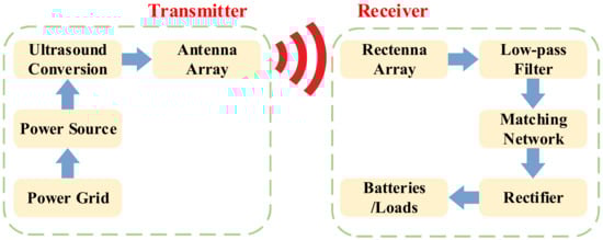
Figure 3. Components and fundamentals of the US-WPT system.
2.2.2. OWPT
Optical Wireless Power Transfer (OWPT) is one of the WPT technologies specifically researched for long-distance directional devices. The components and principles of the OWPT system are shown in Figure 4. The most significant advantage of OWPT is that it can realize long-distance and high-power directional energy transmission, and its transmission distance can even be greater than 1 km. At this stage, the leading service objects of OWPT include UAVs, satellites, and other remote power facilities.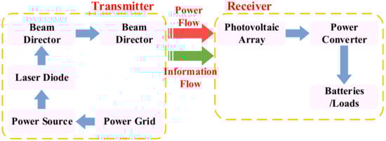
Figure 4. Components and fundamentals of the OWPT system.
| University of Auckland | 2011 |
|
20 |
|
|
| 20 | 2 | 80% | MW-WPT |
|
|
Table 4. Results and parameter indicators of companies on WPT technology.
| Company | Year | Frequency (kHz) | Gap (cm) | Power Level (kW) | Efficiency |
|---|---|---|---|---|---|
| Qualcomm Halo | 2011 | 85 | 22 | 3.3~20 | 90% |
| μi(25 ℃) | 2300 | 3000 | 1500 | 1800 | 2000 |
| 2013 |
|
||||
| ZTE New Energy | 20 | 10~25 | 7 |
Table 7. Requirements and recommends of magnetic materials for the transmitter in Qi standard.
| Types | Fixed Position Type | Single-Coil Free Position Type |
Multi-Coil Free Position Type |
|---|---|---|---|
| Operating frequency | 110~205 kHz | 140 kHz | 105~113 kHz |
| / | |||
| 2014 | 45 | 20 | 30/60 |
| Material requirements | Low loss and magnetic leakage | High reliability | Low loss and high Bs |
| Material recommendations | Material 44 (Fair Rite) Material 28 (Steward Inc.) CMG22G (Ceramic Magnetics) |
Table 8. Microstructure and magnetic properties of three typical nanocrystalline materials.
| Parameters | Finemet | Nanoperm | Hitperm | |||||||||||
|---|---|---|---|---|---|---|---|---|---|---|---|---|---|---|
| Ingredients | Fe73.5Si13.5B9Nb3Cu1 | Fe90Zr7B2Cu1 | Fe44Co44Zr7B4Cu | |||||||||||
| DPR-MF3 (Daido Steel) | ||||||||||||||
| 320 | ||||||||||||||
| 2300 | 3000 | 3000 | 90% | |||||||||||
| 1 | Bs(25 ℃)/mT | 430 | 430 | ~470 | ~50 | 430 | 530 | 430 | 530 | |||||
| Grains | α-Fe(Si) | α-Fe | α-FeCo | OPWT | Bs(100 ℃)/mT |
|
2015 |
|
85 |
|
||||
| 10 | 85 | 1 | 91.3% | |||||||||||
| 6 | 200 | 340 | HS13-H (Daido Steel)340 |
400 | 370 | 340 | 410 | 370 | Material 78 (Fair Rite) 90% |
Near Field | EC-WPT |
|
|
2017
|
| 20 | 15~20 | 1 | 90% | MCR-WPT |
| |||||||||
| KAIST |
|
2.3. The State-of-the-Art of MCR-WPT
The structure of the MCR-WPT system is shown in Figure 7, including the inverter, the compensation network, the magnetic coupler, the rectifier, DC/DC module, and the load [86]. The significant difference between the magnetic coupling resonance type and the traditional inductive power transfer is that the MCR-WPT system adds a resonance compensation network to eliminate the reactive power component in the circuit, which means that the magnetic coupling resonant type can obtain higher active power transmission under the same degree of coil coupling. In other words, when in the case of a longer distance (weak coupling state), it still can have a higher active power output.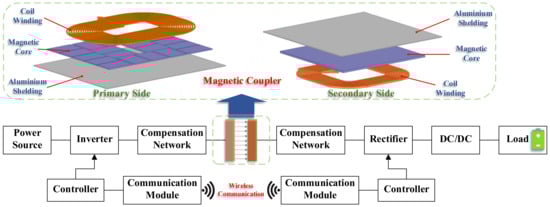
Figure 7. Composition of the MCR–WPT system and its magnetic coupler.
Table 3. Results and parameter indicators of research institutions on WPT technology.
| 2011 | |||||||||
| 100 | |||||||||
| 17 | |||||||||
| WiTricity | 2016 | 85 | 25 | 3.3/7.7/11 | 91~93% | 6 | 72% | ||
| Zone Charge | 2017 | 85 | 2013 | 20 | 12 | 15 | 74% | ||
| 19 | 2014 | 20 | 20 | 27 | 74% | ||||
| 2015 | 20 | 20 | 22 | 91% | |||||
| Korea Railroad Research Institute | 2015 | 60 | 5 | 1000 | 83% | ||||
| 7.7/20/30 | 90% | ORNL | 2018 | / | 15.24 | 120 | 85% | ||
| 2018 | 22 | 12.7 | 50 | 85% | |||||
| University of Michigan | 2017 | 85 | 15 | 3 | 95.5% | ||||
| Bombardier | Saitama University | 2012 | 50 | 20 | 3 | 90% | |||
| HIT | 2015 | 85 | 15 | 3 | 87% | ||||
| 2014 | 2017 | ||||||||
| Momentum Dynamics | 2018 | 85 | 30.5 | 200 | 95% | ||||
| INVIS Power | 2019 | 85 | 14 | 7.7 | 90% | 30 | 30 | 85 | 90% |
| Chongqing University | 2015 | 20 | 20 | 10 | 82.5% | ||||
| 2016 | 40 | 20 | 30 | 90% |
3. Magnetic Materials and Their Applications in WPT
3.1. Brief History of Soft Magnetic Materials
In 1831, through an experiment, Michael Faraday found that when a part of the conductor of a closed circuit cut the magnetic induction line in the magnetic field, the current would be generated in the conductor. Faraday’s law of induction was proposed [104]. Iron is chosen as the magnetic core because of its highest saturation magnetization among all elements. In addition, it also has the characteristics of high permeability and low coercivity. Since then, soft magnetic materials have been developing continuously. Later, the researchers found that the annealing process of iron can improve its mechanical properties and reduce its coercivity through stress relief, making it more suitable for induction applications. In 1900, British metallurgist Robert Hudfield invented non-oriented silicon steel by adding 3% silicon to iron, which improved both the resistivity and saturation magnetization [105]. In 1933, American metallurgist Norman Goss invented grain-oriented silicon steel by promoting grain growth along the direction of low anisotropy crystallization, thus further improving the saturation magnetization. Even today, due to the high saturation magnetization and relatively low cost of silicon steel, it still occupies the main share of the global soft magnet market. The most common applications of silicon steel are large transformers (oriented silicon steel) and motors (isotropic non-oriented silicon steel). However, low resistivity (~0.5 mΩ·m) makes silicon steel lose more at high frequency [106]. Recently, electrical steel manufacturers have developed a method to increase the silicon content in steel to 6.5% by using a chemical vapor deposition process [107]. This method can increase the resistivity of silicon steel material to 82 μΩ·cm but still cannot meet the current high-efficiency requirements of high-frequency power electronic equipment and high-speed motors. In the 1910s, Gustav Elmen of Bell Laboratories carried out experiments on nickel-iron and discovered the nickel-rich (78%) permalloy composition [108]. A significant advantage of permalloy is its high relative permeability (up to 100,000). Nickel-iron is still used in some special induction applications today, but it is not common in power electronics and motors because of their high eddy current loss. Adding nickel can reduce soft magnetic materials’ saturated magnetic flux density. Moly permalloy powder (MPP) can be produced by adding a small amount of molybdenum (2%) to permalloy [109]. MPP is used to fabricate the powder cores with the lowest loss [110], and it is still the best choice for high-frequency inductor cores within the frequency range of 450 kHz. Then in the late 1940s, the soft magnetic ferrites were invented by J. L. Snoek [111]. These materials have high resistivity, which can effectively suppress eddy current loss. In addition, the preparation process of ferrite is often simple so that the ferrite core can be produced at a very low cost. Soft ferrite has been developed rapidly in recent years due to its high resistivity and economic performance and has been widely used in electromagnetic induction and high-frequency equipment. Today, the market share of ferrite in the world’s soft magnetic materials is only second to that of silicon steel sheets [112]. Manganese zinc ferrite is also the most commonly used soft magnetic material in the WPT system at present. However, the saturation flux density of ferrite is relatively low (almost a quarter of that of silicon steel sheets), which limits the energy density of sensing elements containing ferrite cores. Therefore, increasing the maximum saturation flux density of soft ferrite has always been the development direction of the ferrite process. In 1967, Duwez and Lin reported the first amorphous soft magnetic alloy in the form of small disc-shaped samples [113]. They used a rapid solidification technique called splat cooling for Fe-P-C systems. Then interest in Fe- and Co-based amorphous alloys surged by the mid of 1970s. Amorphous alloys obtained some applications because of their excellent coercivity and saturation magnetic density compared with ferrite. In 1988, Hitachi researchers added Nb and Cu additives and added an annealing step in the production of amorphous alloys to produce small and closely distributed the iron or cobalt-based nanocrystals (about 10 nm in diameter) in the matrix of amorphous materials, which marked the invention of nanocrystalline alloys [114]. Amorphous and nanocrystalline alloys have low power loss and competitive saturation flux density. Although the cost is higher than that of silicon steel, due to the low power loss, these advanced alloys can reduce the total lifetime cost of power electronics and motors. In the early 1990s, powder cores (also known as soft magnetic composites or SMCs) were proposed [115]. These materials combine magnetic particles, anywhere between ~1 to 500 mm in diameter, and either coat or mix them with an insulating material before consolidating with high pressures. Moreover, the heat process can also be applied either during or after densification to improve magnetic properties. Magnetic particles are usually iron powder but can also be composed of alloys. Powder magnetic core can be quickly processed into a more complex magnetic core shape, improving its applicability in special equipment and significantly reducing manufacturing costs. Their isotropy, low cost, and the ability to make complex mesh parts make SMC quite successful in rotating electrical machines [116,117]. Although the magnetic permeability of the powder core is usually low, its stability at high frequencies is impressive (such as the MPP mentioned earlier). SMC-based magnetic cores are attractive in high-frequency inductor design. The desired overall core permeability of SMC core can be achieved by adjusting the powder size, addition of insulation material and phosphoric acid, and pressure during the preparation process to reduce the air gap loss and ease the inductor design [118]. Figure 8 shows the brief history and development trend of soft magnetic materials [119,120]. From the perspective of power electronics applications, the saturated magnetic flux density, resistivity, and cost of soft magnetic materials are important concerns in their development. Ferrite material is a competitive core material at high frequency, so it has been in a leading position in the field of WPT technology. In recent years, with the application and popularization of advanced alloys such as amorphous and nanocrystalline alloys, researchers have gradually applied them to various WPT scenarios and obtained some applied results. In the following section, the application of soft magnetic materials and their magnetic structures in WPT technology will be discussed in detail.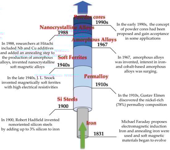
Figure 8. Research progress and a brief history of soft magnetic materials.
3.2. Mn-Zn and Ni-Zn Soft Ferrites
Soft ferrite materials are the most widely used magnetic material in WPT systems at present and are also typical magnetic core materials recommended in SAE-J2954 and Qi standards [35,121,122]. They have remarkable performance in the field of consumer electronics and EVs wireless charging. Among them, Mn-Zn ferrites have high saturated magnetic flux density, permeability, and low resistivity compared with Ni-Zn ferrite. In addition, the performance of Mn-Zn ferrites is generally better than Ni-Zn below 2 MHz. The application of Mn-Zn ferrite materials accounts for about 80% of all ferrite materials. According to different application conditions and performance indicators, Mn-Zn ferrite materials can be divided into two categories. One is high permeability ferrite (generally greater than 15,000), which is usually used in low-frequency broadband transformers and inductance components of communication equipment. The other is high-frequency low-loss ferrite, which is often called power ferrite. Under high frequency and magnetic flux density, the loss of power ferrites does not change much with the increase of temperature in a particular range [123,124]. Power ferrite materials can be used for power conversion and transmission due to the high magnetic flux density Bs, high initial permeability μi, and low power loss Pc characteristics. Mn-Zn power ferrite materials were first used in household appliances, switching power supplies, and adaptive transformers. With the rise of WPT technology, Mn-Zn power ferrites have gradually become the most widely used core material. At the end of the 20th century, material companies developed a set of landmark Mn-Zn power ferrite, which solved the problem of large power consumption and the rapid decline of magnetic properties at 100~500 kHz high-frequency ranges. The maximum saturated magnetic flux density of this high-performance power ferrite is about 500 mT, and the loss at high temperature and frequency (100 kHz, 200 mT, 100 °C) is about 400~500 kW/m3. The most well-known products include PC40 from TDK [125], 6H20 from FDK [126], and N72 from SIEMENS [127]. In the past decade, low Pc ferrite materials have made remarkable progress. The PC45, PC46, and PC47 series Mn-Zn ferrites with low power loss near a temperature range are produced by TDK. The power consumption valley of PC45 is 60~80 °C, PC46 is 40~50 °C, and PC44 and PC47 are around 100 °C. Then, the PC90 and PC95 series Mn-Zn ferrite materials with wide temperatures and low power loss were developed. PC95′s Pc was lower than 350 mW/cm3 in the range of 25~120 °C, while PC90′s Pc was about 320 mW/cm3 at 100 °C. In addition, the Bs of PC90 are 450 mT and 540 mT at 100 °C and 25 °C, respectively. The PC90 and PC95 series Mn-Zn ferrites have wide temperatures and low power loss with excellent comprehensive performance [128]. The performance parameters of TDK PC series Mn-Zn ferrites are shown in Table 5.Table 5. TDK’s PC series Mn-Zn ferrites product parameters.
| Parameters | PC40 | PC44 | PC45 | PC46 | PC47 | PC95 | PC90 | |||||
|---|---|---|---|---|---|---|---|---|---|---|---|---|
| μi(25 °C) | 2300 | 2400 | 2500 | 3200 | 2500 | 2500 | 2200 | |||||
| Bs(25 °C)/mT | 510 | 510 | 530 | 530 | 530 | 530 | 540 | |||||
| Bs(100 °C)/mT | 390 | 390 | 420 | 410 | 420 | 420 | 450 | |||||
| 410 | ||||||||||||
| 3C94 (Ferroxcube.) | N87 (Epcos AG.) PC44 (TDK Corp.) |
Material 78 (Fair Rite) 3C94 (Ferroxcube.) N87 (Epcos AG.) PC44 (TDK Corp.) |
Pc(25 °C, 200 mT, 100 kHz)/mW·cm−3 | 600 | 600 | 570 | ||||||
| D/nm | 10 | 10 | 8 | 350 | 600 | P350 | c(100 ℃, 200 mT,100 kHz)/mW·cm680 | |||||
| −3 | ~450 | <330 | <400 | ~350 | <400 | <330 | <330 | |||||
| B | <300 | s/T | 1.24 | 1.65 | 1.6~2.1 | Pc(100 °C, 200 mT, 100 kHz)/mW·cm−3 | 410 | 300 | 460 | 660 | 250 | 320 |
| Hc/A·m−1 | 0.53 | 2.4 | 10 | Tc/°C | 215 | 215 | 230 | 230 | 230 | 230 | 250 |
Table 6. Ferroxcube’s 3C series Mn-Zn ferrites product parameters.
3.3. Amorphous and Nanocrystalline Alloys
Amorphous and nanocrystalline soft magnetic materials mainly include Fe, Ni, Co, Fe-Ni, and Fe-Co-based materials. Amorphous materials are produced by ultra-rapid cooling solidification technology with a cooling rate of approximately 106 °C/s. The thin ribbons of 15–30 μm thick alloys are formed from the liquid state of the metal in a single process. The atoms of amorphous alloys do not crystallize in an orderly arrangement under the effect of rapid cooling. There are no grains and grain boundaries of crystalline alloys, so they show a long-range disorderly arrangement and exhibit isotropic characteristics. This amorphous state has excellent soft magnetic properties, including high permeability, low coercivity, low magnetic loss, and high saturation magnetic induction strength, while the material is strong and wear resistant. Since amorphous alloys are in a thermodynamically nonequilibrium sub-stable state, under appropriate heat treatment process conditions, amorphous alloys crystallize to obtain precipitated crystalline phases with grain sizes below 20 nm, leading to the preparation of nanocrystalline materials or nanocrystalline/amorphous composites [145]. With their excellent magnetic properties, amorphous and nanocrystalline alloys can replace silicon steel, permalloy, and ferrites. They are widely used in many electromagnetic fields such as distribution transformers, sensors, and electromagnetic shielding. With the rise of near-field communication and wireless charging, the application of amorphous and nanocrystalline materials in the field of electromagnetic shielding and WPT is gradually gaining attention. In the 1970s, researchers developed Fe-Ni-P-B, Fe-Ni-P-B-M, Fe-B, Fe-B-C, Fe-Si-B, Fe-Si-B-M series Fe-based amorphous alloys and Co-based soft magnetic amorphous alloys based on the alloy melt-spin quenching technology [| μ | |||
| i | |||
| /10 | |||
| 3 | |||
| 100 | 17 | 1.8 | |
| λs/10−6 | 2.1 | 1 | 30 |
| Tc/℃ | 570 | 770 | 980 |
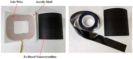
图9.UUV WPT磁耦合器及其铁基纳米晶磁芯在[194]中介绍。