Microinjection moulding has been widely used to mass-produce miniature polymeric devices and/or surface micro/nano structures, such as microneedles for drug delivery [1] and microfluidic devices for diagnostics [2,3]. The base of a microneedle patch is usually a millimetre with a single needle of several hundred micrometres in size, while the tip radius is smaller than 5 µm; such examples also include micro gears, micro-optical connectors, and micro liquid dispensers. These products have an overall weight of the patch of several milligrams or below. The other typical polymeric micro products would be micro/nano scale features on a large substrate, e.g., microfluidic chips. Microfluidic chips usually have tens to hundreds of micron channels for liquid manipulation. Such micro parts and micro/nano scale features are characterised by their very small dimensions and high surface-to-volume ratios.
- microinjection moulding
- polymer devices
- micro/nano structures
1. Microinjection Moulding
When the development of microinjection moulding started in the late 1980s, no appropriate machine technology was available. Only modified commercial units with hydraulic drive function and a clamping force of usually 25–50t could be used to replicate micro features with high aspect ratios by injection moulding [1][9]. Using a conventional injection moulding machine to produce micro parts is challenging. From the perspective of processing, decreasing cavity size poses challenges for filling a cavity, especially when cavity dimensions decrease to the micro and nanometre scale. Firstly, due to the decrease in the size of components, the volume of a moulded part decreases to several cubic millimetres, which requires precise metering of a small amount of polymer and fast injection. Conventional hydraulic injection moulding machines have an injection velocity of 200 mm/s. A fully electrical-driven injection moulding machine can achieve more than 600 mm/s injection velocity. A milligram part requires the precise metering capability to accumulate polymer melts less than several milligrams in one shot. The injection screw/plunger has to be scaled down to several millimetres with the precise motion of several micrometres. Some industrial microinjection moulding trials to produce micro parts with conventional injection moulding machines highlighted problems, such as process consistency, long cycle time and waste of material, residence problem (degradation) due to excess material remaining idle in the barrel. Secondly, because of the small stroke of the injection screw/plunger, an injection unit for a microinjection moulding process must respond extremely fast to reach the required injection pressure/velocity. Thirdly, consistency is of paramount importance for microinjection mounding. Micro moulded parts require extremely demanding tolerances, such as for some optical components, up to ±3 µm. A consistent process must ensure proper and repeatable replication of micro/nano features as well as maintaining tolerance. Fourthly, extreme process conditions modify the microstructure and properties of polymers. Additionally, for replicating micro/nano surface features, the combination of all process parameters should make sure that the macro part has no defects, such as short shot, thermal degradation, flash, and at the same time, ensure that micro/nano features can be replicated with high quality and high consistency. Moreover, a specially designed ejection system is required to demould parts smaller than several millimetres in scale, e.g., suction demoulding, air ejection, etc. Progress in variotherm moulding systems has been made in recent years with various heating methods for microinjection moulding applications, such as electrical resistive heating, induction heating, and infrared radiation [2][10].
1.1. Equipment Development
Table 1
lists some commercially available microinjection moulding machines and their characteristics.
| Manufacturer | Model | Clamp Force (kN) |
Injection Capacity (cm | 3 | ) | Injection Pressure (Bars) |
Plasticization (Screw or Plunger) |
Injection Speed (mm s | −1 | ) |
|---|---|---|---|---|---|---|---|---|---|---|
| Lawton (Fridingen, Germany) |
Sesame Nanomolder | 13.6 | 0.082 | 3500 | 10 mm plunger | 1200 | ||||
| APM (Taichung, Japan) |
SM-5EJ | 50 | 1 | 2450 | 14 mm screw | 800 | ||||
| Battenfeld (Barcelona, Spain) |
Microsystem 50 | 56 | 1.1 | 2500 | 14 mm screw | 760 | ||||
| Nissei (New Taipei, Japan) |
AU3 | 30 | 3.1 | 14 mm screw | ||||||
| Babyplast (Lyon, France) |
Babyplast 6/10 | 62.5 | 4 | 2650 | 10 mm plunger | |||||
| Sodick (Warwick, UK) |
TR05EH | 49 | 4.5 | 1970 | 14 mm screw | 300 | ||||
| Rondol (Nancy, France) |
High Force 5 | 50 | 4.5 | 1600 | 20 mm screw | |||||
| Boy (Exton, PA, United States) |
12/AM | 129 | 4.5 | 2450 | 12 mm screw | |||||
| Toshiba (Troy, MI, United States) |
EC5-01.A | 50 | 6 | 2000 | 14 mm screw | 150 | ||||
| Fanuc (Yamanashi, Japan) |
Roboshot S2000-I 5A | 50 | 6 | 2000 | 14 mm screw | 300 | ||||
| Sumimoto (Suwanee, GA, United States) |
SE7M | 69 | 6.2 | 1960 | 14 mm screw | 300 | ||||
| Milacron (Batavia, NY, United States) |
Si-B 17 A | 147 | 6.2 | 2452 | 14 mm screw | |||||
| MCP (America North (USA-Canada-Mexico)) |
12/90 HSE | 90 | 7 | 1728 | 16 mm screw | 100 | ||||
| Nissei (New Taipei, Japan) |
EP5 Real Mini | 49 | 8 | 1960 | 16 mm screw | 250 | ||||
| Toshiba (Michigan, United States) |
NP7 | 69 | 10 | 2270 | 16 mm screw | 180 |
12.1.1. Single-Step System
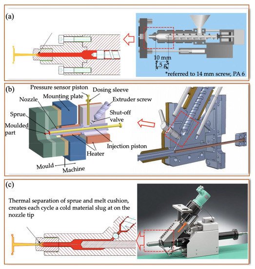
2.1.2. Two-Step System
2.1.3. Three-Step System
2.2. Process-Rheology and Crystallisation and Morphology of Micro Products
2.2.1. Rheology of Polymer Material at Micro Scale
Rheology means flow and deformation [10][19]. Understanding polymer melt rheology at the micro/nano scale is important for quality control, process design, and simulation of micro/nano features [11][20]. It was evidenced that liquids such as water, silicon oil, alcohol, and polymer solutions flowing in microchannels with characteristic dimensions of tens of micrometres had a viscosity of 50–80% close to the channel, where the viscosity was higher than that of the bulk fluid [12][21]. The higher viscosity increase was attributed to collective molecular motion effects or to the immobility of the layer of molecules in contact with the solid surface [13][22]. Generally, techniques such as rotational, capillary, or slit flows are used to obtain accurate measurements at a series of set strain rates and temperatures [14][23]. Additionally, viscous fluids adhere to attain the velocity of the boundary during flow. However, a relative velocity exists at the contact line between the fluid and solid boundary during flow: this is the so-called “wall slip” [15][30]. Slips of polymer melts are explained by flow-induced chain detachment/desorption and chain disentanglement. The various experimental methods of determining wall slip velocity can be found [16]in an excellent review [31]. In microinjection moulding, polymer melts are subject to very high shear stresses, which can easily exceed the critical shear stress. Since a cavity is reduced to the micro scale, the effect of wall slip would be more significant than the conventional injection moulding.2.2.2. Crystallisation and Morphology Development
Morphology is the study of form and structure. Polymer morphology is the study of order within macromolecular solids. The thermomechanical history experienced by polymer materials in their processing imparts to its microstructure (crystallinity, morphology, orientation, and residual stress, etc.), as shown in Figure 28. It is evident that the three transport phenomena (flow, heat transfer, and crystallisation kinetics) are involved in structure formation during processing [17][34]. Flow causes macroscopic heat and momentum transport. Meanwhile, it also influences crystallisation kinetics by controlling stress, strain, and strain rates. This microstructure will ultimately determine the product properties (mechanical, optical, and barrier, etc.). As a result, characterisation of multiscale microstructure and prediction of microstructure at micro, nano, and/or molecular scales are important aspects of polymer processing research. Microinjection moulding refers to miniaturized parts or micro/nano scale features. In this process, the material will experience a very high shear rate, injection pressure, and thermal gradients. These extreme process conditions will create a special morphology. This section will review prior work on characterising morphology evolution for both micro parts and micro features and final properties.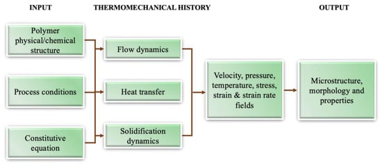
2.3. Tooling
| Technology | Minimum Feature Size (µm) | Surface Roughness (µm) | Aspect Ratio | Material | Manufacturing Cost ($) | Other Applications |
|---|---|---|---|---|---|---|
| Micro milling | 25–100 | 0.2–5 | 10 | Brass, COC, Steel | 500~1000 | Microstructures and micro-texturing in MEMS devices, micro-fuel cells, microfluidic chips, EDM electrodes, and optics, etc. |
| Micro electro discharge machining | 10–25 | 0.05–1 | 50–100 | Conductive material | ~3000 | Inkjet nozzles of printers, cooling holes of turbine blades, and honeycomb structures, etc. |
| Micro laser machining | 1–5 | 0.4–1 | <50 | Any | ~3000 | Photonics, surface plasma resonance, optoelectronics, bio-sensing, micro/nanofluidic, etc. |
| Micro electrochemical machining | 10 | 0.02 | NA | Conductive material | NA | Turbine blades, shaving heads, artillery projectiles, and surgical implants, etc. |
| X-ray lithography | 0.5 | 0.02 | 100 | Photoresist | >10,000 | Diffractive and refractive optics, spectrometer, X-ray grating interferometry, and mask, etc. |
| Ultraviolet lithography | 0.7–1.5 | NA | 22 | Photoresist | 1000 | |
| Deep reactive ion etching | 2 | NA | 10-20 | Silicon | 1000~3000 | MEMS devices, memory circuits, mask, and flexible electronics, etc. |
| Focused ion beam lithography | 0.1 | NA | 3 | Any | 1000~5000 | Semiconductor devices, integrated circuits, bio-sensing, and nano-optics, etc. |
| Electroforming | 0.3 | 0.1 | <10 | Conductive material | 1000~3000 | CDs, DVDs, Blu-ray discs, metal mesh, micro-optics, microfluidics, and microelectronics, etc. |
For mass production, especially injection moulding, stainless steel can resist wear or other forms of surface or structural degradation over several thousands of moulding cycles, and is a good tool candidate from the perspective of wear and tool life [19][20][21][87,88,89]. Direct machining using micro-manufacturing methods, such as micro milling and micro electro-discharge machining, takes a very long time to machine macro features. Combining conventional machining with micromachining could reduce the total machining time, but it would generate more roughness and burrs.
2.4. Replication of High Aspect Ratio and Submicron Scale Features
Separation and mixing of fluids are common operations in chemical and biological assays. When scaling down to microfluidics, these operations are usually achieved by micropillar arrays. Figure 3 24 shows an electrochromatography pattern, formed by imprinting a COC substrate using a silicon master. The aspect ratio of the individual pattern and spacing are 1.5 and 2.5 [22][102]. Changing the surface energy by patterning the surface with high aspect ratio features has also been widely used to functionalize the polymer surface for cell or bacteria culture. However, high aspect ratio features are inclined to solidify before the cavity is fully filled. This is similar to the frozen layer problem in thin wall injection moulding. Because of limits in machine capability and material processability, the injection speed and pressure that are required over such a short cooling time are difficult to achieve in practice. When polymer melt is injected into a cavity with various thickness features, it tends to fill thicker and less resistant areas. Free-standing pillar arrays are typical features on a thick substrate. Consequently, flow hesitates at the entrance of micro features until a much thicker substrate is fully filled. The resulting hesitation time is longer than the critical cooling time of micro features, and the polymer tends to solidify at the stagnated point.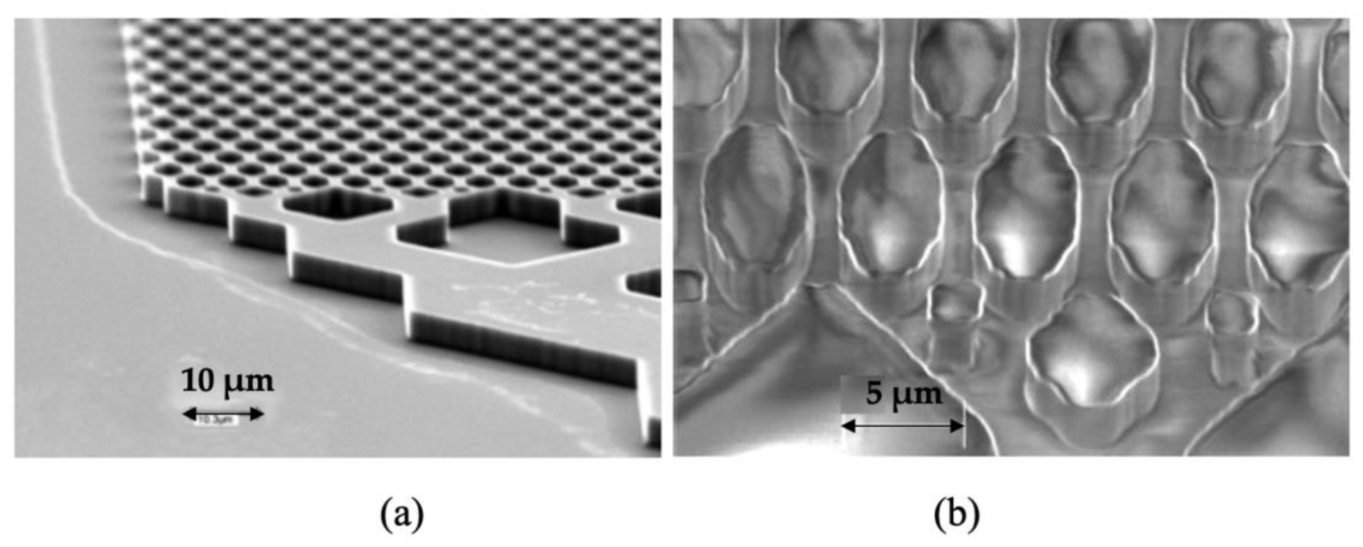 Figure 3. Electrochromatography microchip: (a) inlet and the separation column on silicon imprint master (5.1 µm in height) and (b) imprinted features on COC substrate [22].
3. Application of Microinjection Moulded Polymeric Devices
3.1. Drug Delivery
Microneedles (MNs) are comprised of many micro-projections with a wide range of geometrical designs, including different sizes in height generally from 25 µm to 2000 µm, and different shapes (solid, hollow, sharp, or flat). The MNs biological-membranes medical device has demonstrated the potential applications in drug and gene delivery by creating more molecular transportation pathways at the micro scale or even nano scale, such as the delivery of DNA into the cell [23][106]. The primary working principle of MNs is to penetrate the skin and directly puncture into the viable epidermis, preventing the touching of nerves and blood vessels. Therefore, the leading benefit of utilising MNs is to achieve pain-free delivery of drugs and offer better manoeuvrability of drug delivery [24][107]. Devoted to next-generation therapeutics, a great number of medical companies and academic communities are actively participating in the research and development of MNs.