Your browser does not fully support modern features. Please upgrade for a smoother experience.
Please note this is a comparison between Version 1 by Waqas Amin Gill and Version 3 by Vivi Li.
Micro-electromechanical systems (MEMS) vibrating gyroscopes have gained a lot of attention over the last two decades because of their low power consumption, easy integration, and low fabrication cost. The usage of the gyroscope equipped with an inertial measurement unit has increased tremendously, with applications ranging from household devices to smart electronics to military equipment. However, reliability issues are still a concern when operating this inertial sensor in harsh environments, such as to control the movement and alignment of mini-satellites in space, tracking firefighters at an elevated temperature, and assisting aircraft navigation in gusty turbulent air.
- MEMS vibrating gyroscope
- tuning fork
- gimbal
- vibrating ring
- mode mismatch
- frequency modulated
- rate integrated
- space applications
- vibratory ring gyroscope
- mode matching
1. Introduction
The gyroscope is an inertial sensor that is used for the measurement or control of the orientation and rotational velocity of a body. In the early 17th century, people occasionally used spinning mass objects for navigation purposes. The spinning mass gyroscope concept was first developed by French scientist Jean Bernard Leon Foucault in 1852 [1]. In the late 18th century, the usage of the gyroscope was extended to ship navigation at sea. At the beginning of the 20th century, the traditional spinning mass gyroscope started to be used in aircraft [2]. In the 1960s, the concept of optical lasers for gyroscopes was introduced, which provided higher precision and better sensitivity and brought a tremendous leap forward for aerospace and military applications [3]. However, the costs associated with optical gyroscopes were quite high, and this provided motivation for the development of micro-electromechanical systems (MEMS) vibrating gyroscopes. Over the past few decades, a large number of MEMS gyroscopic technologies have been developed with high sensitivity, high scale factor, and reduced fabrication costs [4].
Nowadays, in peopleur daily life routine, smart devices are commonly used for tracking and their navigation capability requires global positioning systems, such as mobile phones, smartwatches, and vehicles. The navigation systems comprise inertial measurement units (IMU) [5], which are installed in the smart electronic devices [6]. The IMU typically consists of multiple inertial sensors, including a gyroscope, accelerometer, and magnetometers. All of these sensors work from different scientific principles: the gyroscope is a rotational motion inertial sensor that detects the change of position when rotation occurs, the accelerometer is a translational motion sensor that detects linear acceleration [7], and the magnetometer gives guidance in the coordinate system [8].
The usage of the MEMS gyroscope has increased enormously over the last 20 years. These sensors have been extensively used in smart devices, automotive industries, household applications, aerospace, military applications, and so on [9][10][9,10]. The research on the MEMS vibratory gyroscopes started gaining maturity and moved towards practical designs at the start of the 21st century. In the early stages, only a few research groups tended to research in this area. However, at the beginning of the 2000s, more research groups showed interest and developed a variety of designs for MEMS vibrating gyroscopes [11]. The gyroscope’s sensitivity and performance degrade when it is exposed to an unwanted atmosphere. Some of the prominent issues that deteriorate the stability and reliability of MEMS for gyroscopes range from microfabrication process stability (beam stiffness, material properties, and critical dimension losses) to exposure to harsh environments (space, elevated temperature, radiation) and external vibrations. This rentryview paper discusses: (1) the basic operations of the MEMS vibratory gyroscopes, (2) the development of the various types of gyroscopes, and (3) the potential reliability issues with the MEMS vibrating gyroscopes at elevated temperatures, high external vibrations, and some microfabrication processing errors.
2. Micro-Electromechanical Systems (MEMS) Vibrating Gyroscopes
In the evolution of integrated circuit (IC) technology, the miniaturization of micro-electromechanical system sensors played a significant role in scaling down the device sizes. The demand for MEMS vibrating gyroscopes in sensor applications has increased significantly because of their small and compact size, energy efficiency, overall low fabrication cost, high performance and sensitivity, and batch fabrication [12][21]. Exhaustive research has been conducted on many types of gyroscopes such as dual-axis, multi-axis, single-axis, single mass, dual mass, and decoupled gyroscopes. The MEMS gyroscope operates on different mechanisms. The most commonly adopted mechanisms are electrostatic [13][14][22,23] and piezoelectric [15][16][24,25], compared to electromagnet [17][26] and electrothermal [18][27] mechanisms. In recent developments, some key gyroscope designs such as vibrating-ring, tuning fork, decoupled, and dual mass [19][28] were found to be the most popular gyroscope structures [20][29]. There are four main types of MEMS vibrating gyroscopes discussed in this section.2.1. Gimbal Gyroscopes
The term MEMS gimbal gyroscope is conceptualized from the traditional spinning-rotor gimbal gyroscope, where a spinning rotor is mounted on two freely gimbal systems: inner and outer gimbal systems. Earlier, in military applications, the dynamic tuning gyroscope and control moment gyroscope were used for maintaining and measuring the movement of satellites [21][30]. However, in the late 1980s, the Draper laboratory started its investigation on the usage of vibrating elements for gyroscopic purposes. The first micromachined gyroscope was developed by the Draper laboratory in 1988 [22][31]. Boxenhorn et al. demonstrated a first novel micromachined gyroscope in which there was no rotating part. The gyroscope structure was constructed on two gimbal systems: one was outer, and the other was an inner gimbal. A vertical bar was mounted on the inner gimbal. The inner gimbal constituted the sensitive element, while the outer gimbal was attached to a motor. Both gimbals were connected via orthogonal flexural pivots; the outer gimbal was used to vibrate on the given frequency and made the inner gimbal sensitive enough to detect the rotational motion on any external rotation. Furthermore, they fabricated a silicon monolithic micromechanical gyroscope. All of the design features were fabricated on the same substrate, which was the initiation of the mass production of this small-sized vibrating gyroscope. The dimensions of the gimbal structure were 350 µm × 500 µm. The outer gimbal was driven electrostatically by the electrodes at a given amplitude. This movement was transferred to the inner gimbal, making the inertial element oscillate. When rotation was applied to the gyroscope, the Coriolis force shifted the inner gimbal oscillation towards the weak axis with an equal amplitude of driving frequency. The output motion of the inner gimbal was sensed capacitively by the sensing electrodes placed near the gimbal structure. A schematic diagram of a micromachined gimbal gyroscope is shown in Figure 1 [23]6 [32].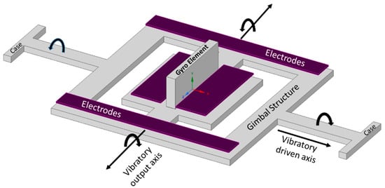
Figure 16.
Schematic diagram of Draper laboratory’s micromachined gimbal gyroscope.
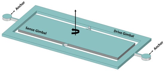
Figure 27.
Ni–Fe alloy-based two-gimbal system gyroscope.
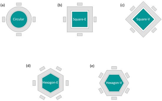
Figure 38. Study of different shapes of an MEMS vibrating wheel on a gimbal gyroscope. (a) circular (b) square-edge (c) square-vertex (d) hexagon-edge (e) hexagon-vertex.
2.2. Tuning Fork Gyroscopes
Tuning fork gyroscopes are one of the most popular designs of MEMS gyroscopes. These designs have two identical masses driven with equal amplitude, but in opposite directions [30][39]. When the rotational motion comes into place that is perpendicular to the driving axis, this motion produces a Coriolis force that shifts the driving motion towards the sensing axis. The driving and sensing mechanism using electrostatic actuation and capacitive sensing, respectively, provides enhanced sensitivity levels compared to the other designs [31][40]. A schematic illustration of the working operation of the MEMS tuning fork gyroscope is shown in Figure 49.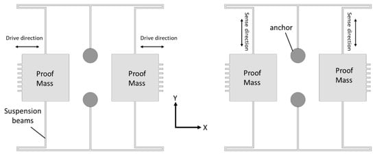
Figure 49.
Working operation of a basic MEMS tuning fork gyroscope.
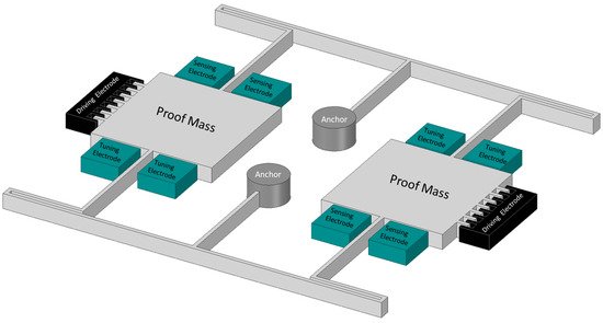
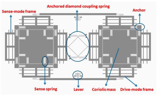
Figure 510.
Schematic diagram of high Q MEMS tuning fork gyroscope.
2.3. Vibrating Ring Gyroscopes
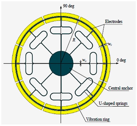
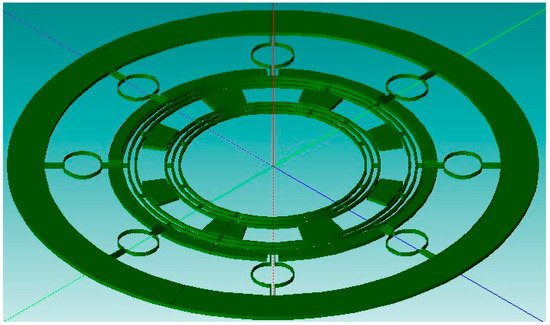
Vibrating ring gyroscopes have a symmetrical structure and provide many advantages over other gyroscope designs. They possess high precision, high resolution, better thermal stability, better matching of operating frequencies, a low zero-output rate, and increased sensitivity [38][47]. The basic design of the MEMS vibrating ring gyroscope is shown in Figure 813. It consists of an outer ring with eight springs that are supported by a circular anchor placed in the middle.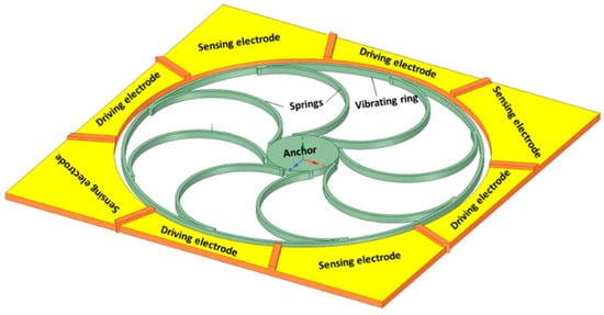
Figure 813.
Schematic representation of the basic design of a vibrating ring gyroscope.
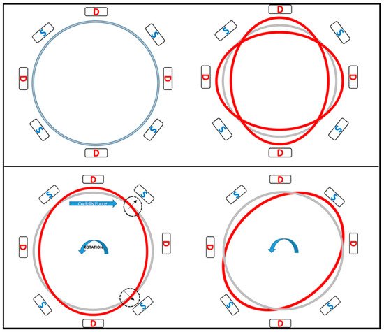
Figure 914.
Schematic demonstration of the operation of a vibrating ring gyroscope.
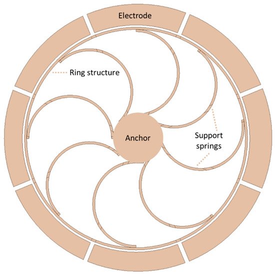
Figure 105.
Schematic view of a novel vibrating ring gyroscope developed by General Motors.
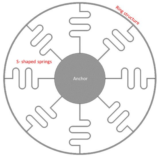
Figure 116.
Schematic view of eight S-shaped support springs in a vibrating ring gyroscope.
2.4. Multi-Axis Gyroscopes
A novel two-dimensional micromechanical gyroscope was developed by Fujita et al. [51][60]. The novel design, which is shown in Figure 149, included four cantilever plates that were placed above the glass substrate with four fixed electrodes. When rotation was applied to the micro gyroscope, the movement was triggered by the Coriolis force and was detected capacitively upon the displacement changing between the cantilever and the fixed electrodes. They proposed to match the driving and sensing frequency for the overall enhancement of the sensitivity of the gyroscope. The sensitivity recorded for this two-dimensional gyroscope was 0.1 mV/deg/s.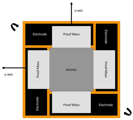
Figure 149.
Schematic diagram of novel two-dimensional micromachined gyroscope developed by Fujita et al.
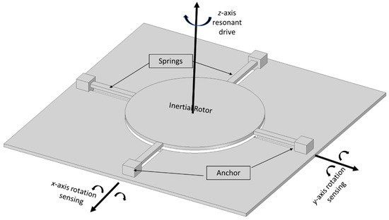
Figure 1520.
Schematic diagram of a dual-axis micromachined vibrating gyroscope.
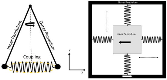
Figure 216. Schematic diagram of dual Foucault pendulum gyroscope. Two Foucault pendulums vibrate in antiphase motion.
Schematic diagram of dual Foucault pendulum gyroscope. Two Foucault pendulums vibrate in antiphase motion.
References
- Turner, G. History of Gyroscopes. 2004. Available online: http://www.gyroscopes.org/history.asp (accessed on 1 August 2022).
- Tazartes, D. (Ed.) An historical perspective on inertial navigation systems. In Proceedings of the 2014 International Symposium on Inertial Sensors and Systems (ISISS), Laguna Beach, CA, USA, 25–26 February 2014; IEEE: Piscataway, NJ, USA, 2014. [Google Scholar]
- Bergh, R.; Lefevre, H.; Shaw, H. An overview of fiber-optic gyroscopes. J. Lightwave Technol. 1984, 2, 91–107. [Google Scholar] [CrossRef]
- Seeger, J.; Lim, M.; Nasiri, S. (Eds.) Development of High-Performance High-Volume Consumer MEMS Gyroscopes; Solid-State Sensors, Actuators, and Microsystems Workshop: Hilton Head Island, SC, USA, 2010. [Google Scholar]
- Mohammed, Z.; Gill, W.; Rasras, M. Modelling optimization and characterization of inertial sensors. In Nanoscale Semiconductor Devices, MEMS, and Sensors: Outlook and Challenges; Springer: Berlin/Heidelberg, Germany, 2017. [Google Scholar]
- De Groote, F.; Vandevyvere, S.; Vanhevel, F.; Orban de Xivry, J.-J. Validation of a smartphone embedded inertial measurement unit for measuring postural stability in older adults. Gait Posture 2021, 84, 17–23. [Google Scholar] [CrossRef] [PubMed]
- Mohammed, Z.; Gill, W.A.; Rasras, M.J.I.S.L. Double-comb-finger design to eliminate cross-axis sensitivity in a dual-axis accelerometer. IEEE Sens. Lett. 2017, 1, 1–4. [Google Scholar] [CrossRef]
- Ren, D.; Yan, M.; You, Z.J.T.; Technologies, M. Principle and research progress of resonant MEMS magnetometer. Transducer Microsyst. Technol. 2007, 26, 10–12. [Google Scholar]
- Wendel, J.; Meister, O.; Schlaile, C.; Trommer, G.F. An integrated GPS/MEMS-IMU navigation system for an autonomous helicopter. Aerosp. Sci. Technol. 2006, 10, 527–533. [Google Scholar] [CrossRef]
- Gaura, E.; Newman, R. Smart MEMS and Sensor Systems; World Scientific: Singapore, 2006. [Google Scholar] [CrossRef]
- Korvink, J.; Paul, O. MEMS: A Practical Guide of Design, Analysis, and Applications; Springer Science & Business Media: Berlin/Heidelberg, Germany, 2010. [Google Scholar]
- Younis, M.I. MEMS Linear and Nonlinear Statics and Dynamics; Springer Science & Business Media: Berlin/Heidelberg, Germany, 2011. [Google Scholar]
- Acar, C.; Shkel, A. MEMS Vibratory Gyroscopes: Structural Approaches to Improve Robustness; Springer Science & Business Media: Berlin/Heidelberg, Germany, 2008. [Google Scholar]
- Acar, C.; Shkel, A.; Costlow, L.; Madni, A. Inherently Robust Micromachined Gyroscopes with 2-DOF Sense-Mode Oscillator. J. Microelectromech. Syst. 2006, 15, 380–387. [Google Scholar] [CrossRef]
- Acar, C.; Shkel, A. An approach for increasing drive-mode bandwidth of MEMS vibratory gyroscopes. J. Microelectromech. Syst. 2005, 14, 520–528. [Google Scholar] [CrossRef]
- Dong, L.; Avanesian, D. Drive-Mode Control for Vibrational MEMS Gyroscopes. IEEE Trans. Ind. Electron. 2008, 56, 956–963. [Google Scholar] [CrossRef]
- Acar, C.; Schofield, A.R.; Trusov, A.A.; Costlow, L.E.; Shkel, A.M. Environmentally robust MEMS vibratory gyroscopes for auto-motive applications. IEEE Sens. J. 2009, 9, 1895–1906. [Google Scholar] [CrossRef]
- Ghisi, A.; Mariani, S. Effect of Imperfections Due to Material Heterogeneity on the Offset of Polysilicon MEMS Structures. Sensors 2019, 19, 3256. [Google Scholar] [CrossRef]
- Ma, Z.; Chen, X.; Jin, X.; Jin, Y.; Zheng, X.; Jin, Z. Effects of Structural Dimension Variation on the Vibration of MEMS Ring-Based Gyroscopes. Micromachines 2021, 12, 1483. [Google Scholar] [CrossRef] [PubMed]
- Behera, A.R.; Shaik, H.; Rao, G.M.; Pratap, R. A Technique for Estimation of Residual Stress and Young’s Modulus of Compressively Stressed Thin Films Using Microfabricated Beams. J. Microelectromech. Syst. 2019, 28, 1039–1054. [Google Scholar] [CrossRef]
- Passaro, V.M.N.; Cuccovillo, A.; Vaiani, L.; De Carlo, M.; Campanella, C.E. Gyroscope Technology and Applications: A Review in the Industrial Perspective. Sensors 2017, 17, 2284. [Google Scholar] [CrossRef] [PubMed]
- Liu, K.; Zhang, W.; Chen, W.; Li, K.; Dai, F.; Cui, F.; Wu, X.; Ma, G.; Xiao, Q. The development of micro-gyroscope technology. J. Microme-Chanics Microeng. 2009, 19, 113001. [Google Scholar] [CrossRef]
- Pistorio, F.; Saleem, M.M.; Somà, A. A Dual-Mass Resonant MEMS Gyroscope Design with Electrostatic Tuning for Frequency Mismatch Compensation. Appl. Sci. 2021, 11, 1129. [Google Scholar] [CrossRef]
- Nguyen, N.M.; Chang, C.-Y.; Pillai, G.; Li, S.-S. Design of piezoelectric MEMS bulk acoustic wave mode-matched gyro-scopes based on support transducer. In Proceedings of the 2021 IEEE 34th International Conference on Micro Electro Mechanical Systems (MEMS), Gainesville, FL, USA, 25–29 January 2021. [Google Scholar]
- Iga, Y.; Kanda, K.; Fujita, T.; Higuchi, K.; Maenaka, K. A design and fabrication of mems gyroscope using PZT thin films. In Proceedings of the 2010 World Automation Congress, Kobe, Japan, 19–23 September 2010. [Google Scholar]
- Yeh, C.; Tsai, J.; Shieh, R.; Tseng, F.; Li, C.; Su, Y. A vertically supported ring-type mems gyroscope utilizing electromag-netic actuation and sensing. In Proceedings of the 2008 IEEE International Conference on Electron Devices and Solid-State Circuits, Hong Kong, China, 8–10 December 2008. [Google Scholar]
- Saqib, M.; Mubasher Saleem, M.; Mazhar, N.; Awan, S.U.; Shahbaz Khan, U. Design and analysis of a high-gain and robust mul-ti-DOF electro-thermally actuated MEMS gyroscope. Micromachines 2018, 9, 577. [Google Scholar] [CrossRef] [PubMed]
- Senkal, D.; Efimovskaya, A.; Shkel, A.M. Minimal realization of dynamically balanced lumped mass WA gyroscope: Dual foucault pendulum. In Proceedings of the 2015 IEEE International Symposium on Inertial Sensors and Systems (ISISS), Hapuna Beach, HI, USA, 23–26 March 2015. [Google Scholar]
- Zhanshe, G.; Fucheng, C.; Boyu, L.; Le, C.; Chao, L.; Ke, S. Research development of silicon MEMS gyroscopes: A review. Microsyst. Technol. 2015, 21, 2053–2066. [Google Scholar] [CrossRef]
- Armenise, M.N.; Ciminelli, C.; Dell’Olio, F.; Passaro, V.M. Advances in Gyroscope Technologies; Springer Science & Business Media: Berlin/Heidelberg, Germany, 2010. [Google Scholar]
- Boxenhorn, B.; Greiff, P. A vibratory micromechanical gyroscope. Guid. Navig. Control. Conf. 1988. [Google Scholar] [CrossRef]
- Greiff, P.; Boxenhorn, B.; King, T.; Niles, L. Silicon monolithic micromechanical gyroscope. In Proceedings of the TRANSDUCERS’91: 1991 International Conference on Solid-State Sensors and Actuators Digest of Technical Papers, San Francisco, CA, USA, 24–27 June 1991. [Google Scholar]
- Greiff, P.; Antkowiak, B.; Campbell, J.; Petrovich, A. Vibrating wheel micromechanical gyro. In Proceedings of the Position, Location and Navigation Symposium-PLANS’96, Atlanta, GA, USA, 22–25 April 1996. [Google Scholar]
- Bernstein, J.; Cho, S.; King, A.; Kourepenis, A.; Maciel, P.; Weinberg, M. A micromachined comb-drive tuning fork rate gyroscope. In Proceedings of the IEEE Micro Electro Mechanical Systems, Fort Lauderdale, FL, USA, 10 February 1993. [Google Scholar]
- Geiger, W.; Folkmer, B.; Merz, J.; Sandmaier, H.; Lang, W. A new silicon rate gyroscope. Sens. Actuators A Phys. 1999, 73, 45–51. [Google Scholar] [CrossRef]
- Maenaka, K.; Ioku, S.; Sawai, N.; Fujita, T.; Takayama, Y. Design, fabrication and operation of MEMS gimbal gyroscope. Sens. Actuators A Phys. 2005, 121, 6–15. [Google Scholar] [CrossRef]
- Jain, A.; Shekhar, C.; Gopal, R. Fabrication of two-gimbal Ni–Fe torsional micro-gyroscope by SU-8 based UV-LIGA process. Microsyst. Technol. 2014, 21, 1479–1487. [Google Scholar] [CrossRef]
- Lee, J.S.; An, B.H.; Mansouri, M.; Al Yassi, H.; Taha, I.; Gill, W.A.; Choi, D.S. MEMS vibrating wheel on gimbal gyroscope with high scale factor. Microsyst. Technol. 2019, 25, 4645–4650. [Google Scholar] [CrossRef]
- Van Vu, T.; Tran, D.Q.; Chu, T.D. Matching mechanical response for a MEMS vibratory tuning fork gyroscope. Microsyst. Technol. 2020, 26, 3865–3874. [Google Scholar] [CrossRef]
- Dong, X.; Huang, Q.; Yang, S.; Huang, Y.; En, Y. Model and experiment of scale factor acceleration sensitivity of MEMS gyroscope in high acceleration environment. Microsyst. Technol. 2018, 25, 3097–3103. [Google Scholar] [CrossRef]
- Che, L.; Xiong, B.; Li, Y.; Wang, Y. A novel electrostatic-driven tuning fork micromachined gyroscope with a bar structure op-erating at atmospheric pressure. J. Micromech. Microeng. 2009, 20, 015025. [Google Scholar] [CrossRef]
- Sharma, A.; Zaman, F.; Amini, B.; Ayazi, F. A high-Q in-plane SOI tuning fork gyroscope. In Proceedings of the SENSORS, Vienna, Austria, 24–27 October 2004; pp. 467–470. [Google Scholar] [CrossRef]
- Nguyen, M.N.; Ha, N.S.; Nguyen, L.Q.; Chu, H.M.; Vu, H.N. Z-axis micromachined tuning fork gyroscope with low air damping. Micromachines 2017, 8, 42. [Google Scholar] [CrossRef]
- Guan, Y.; Gao, S.; Jin, L.; Cao, L. Design and vibration sensitivity of a MEMS tuning fork gyroscope with anchored coupling mechanism. Microsyst. Technol. 2015, 22, 247–254. [Google Scholar] [CrossRef]
- Guan, Y.; Gao, S.; Liu, H.; Jin, L.; Niu, S. Design and Vibration Sensitivity Analysis of a MEMS Tuning Fork Gyroscope with an Anchored Diamond Coupling Mechanism. Sensors 2016, 16, 468. [Google Scholar] [CrossRef]
- Trusov, A.A.; Prikhodko, I.P.; Zotov, S.A.; Schofield, A.R.; Shkel, A.M. Ultra-high Q silicon gyroscopes with interchangeable rate and whole angle modes of operation. In Proceedings of the SENSORS, Waikoloa, HI, USA, 1–4 November 2010; pp. 864–867. [Google Scholar] [CrossRef]
- Xia, D.; Yu, C.; Kong, L. The Development of Micromachined Gyroscope Structure and Circuitry Technology. Sensors 2014, 14, 1394–1473. [Google Scholar] [CrossRef]
- Putty, M.W.; Eddy, D.S. Microstructure for Vibratory Gyroscope. U.S. Patent 5,450,751, 19 September 1995. [Google Scholar]
- Ayazi, F.; Najafi, K. Design and fabrication of high-performance polysilicon vibrating ring gyroscope. In Proceedings of the IEEE Eleventh Annual International Workshop on Micro Electro Mechanical Systems An Investigation of Micro Structures, Sensors, Actuators, Machines and Systems, Heidelberg, Germany, 25–29 January 1998. [Google Scholar]
- Ayazi, F.; Najafi, K. A HARPSS polysilicon vibrating ring gyroscope. J. Microelectromech. Syst. 2001, 10, 169–179. [Google Scholar] [CrossRef]
- Ayazi, F.; Chen, H.; Kocer, F.; He, G.; Najafi, K. A High Aspect-Ratio Polysilicon Vibrating Ring Gyroscope. In Proceedings of the Solid-State Sensor Actuator Workshop, Hilton Head Island, SC, USA, 4–8 June 2000; Volume 10, pp. 4–8. [Google Scholar] [CrossRef]
- Guohong, H.; Najafi, K. A Single-Crystal Silicon Vibrating Ring Gyroscope. In Proceedings of the Technical Digest MEMS 2002 IEEE International Conference Fifteenth IEEE International Conference on Micro Electro Mechanical Systems, Las Vegas, NV, USA, 24 January 2002. [Google Scholar]
- Kou, Z.; Liu, J.; Cao, H.; Shi, Y.; Ren, J.; Zhang, Y. A novel MEMS S-springs vibrating ring gyroscope with atmosphere package. AIP Adv. 2017, 7, 125301. [Google Scholar] [CrossRef]
- Kou, Z.; Cui, X.; Cao, H.; Li, B. Analysis and Study of a MEMS Vibrating Ring Gyroscope with High Sensitivity. In Proceedings of the 2020 IEEE 5th Information Technology and Mechatronics Engineering Conference (ITOEC), Chongqing, China, 12–14 June 2020. [Google Scholar]
- Syed, W.U.; An, B.H.; Gill, W.A.; Saeed, N.; Al-Shaibah, M.S.; Al Dahmani, S.; Choi, D.S.; Elfadel, I.A.M. Sensor Design Migration: The Case of a VRG. IEEE Sens. J. 2019, 19, 10336–10346. [Google Scholar] [CrossRef]
- Cao, H.; Liu, Y.; Kou, Z.; Zhang, Y.; Shao, X.; Gao, J.; Huang, K.; Shi, Y.; Tang, J.; Shen, C.; et al. Design, Fabrication and Experiment of Double U-Beam MEMS Vibration Ring Gyroscope. Micromachines 2019, 10, 186. [Google Scholar] [CrossRef] [PubMed]
- Gill, W.A.; Ali, D.; An, B.H.; Syed, W.U.; Saeed, N.; Al-Shaibah, M.; Elfadel, I.M.; Al Dahmani, S.; Choi, D.S. MEMS multi-vibrating ring gyroscope for space applications. Microsyst. Technol. 2020, 26, 2527–2533. [Google Scholar] [CrossRef]
- Liang, F.; Liang, D.-D.; Qian, Y.-J. Dynamical analysis of an improved MEMS ring gyroscope encircled by piezoelectric film. Int. J. Mech. Sci. 2020, 187, 105915. [Google Scholar] [CrossRef]
- Liang, F.; Liang, D.-D.; Qian, Y.-J. Nonlinear Performance of MEMS Vibratory Ring Gyroscope. Acta Mech. Solida Sin. 2020, 34, 65–78. [Google Scholar] [CrossRef]
- Fujita, T.; Mizuno, T.; Kenny, R.; Maenaka, K.; Maeda, M. Two-dimensional micromachined gyroscope. In Proceedings of the International Solid State Sensors and Actuators Conference (Transducers’ 97), Chicago, IL, USA, 19 June 1997. [Google Scholar]
- Juneau, T.; Pisano, A.; Smith, J.H. Dual axis operation of a micromachined rate gyroscope. In Proceedings of the International Solid State Sensors and Actuators Conference (Transducers’ 97), Chicago, IL, USA, 19 June 1997. [Google Scholar]
- Tang, T.K.; Gutierrez, R.C.; Stell, C.B.; Vorperian, V.; Arakaki, G.A.; Rice, J.T.; Li, W.J.; Chakraborty, I.; Shcheglov, K.; Wilcox, J.Z.; et al. A packaged silicon MEMS vibratory gy-roscope for microspacecraft. In Proceedings of the IEEE The Tenth Annual International Workshop on Micro Electro Mechanical Systems An Investigation of Micro Structures, Sensors, Actuators, Machines and Robots, Nagoya, Japan, 26–30 January 1997. [Google Scholar]
- Kang, M.-S.; Youn, S.-K.; Cho, Y.-H.; Lee, K.B. Dynamic modeling of a tunable microgyroscope. Sens. Mater. 1998, 10, 413–424. [Google Scholar]
- Prikhodko, I.P.; Zotov, S.A.; Trusov, A.A.; Shkel, A.M. Foucault pendulum on a chip: Angle measuring silicon MEMS gyroscope. In Proceedings of the 2011 IEEE 24th International Conference on Micro Electro Mechanical Systems, Cancun, Mexico, 23–27 January 2011. [Google Scholar]
- Prikhodko, I.P.; Zotov, S.A.; Trusov, A.A.; Shkel, A.M. Foucault pendulum on a chip: Rate integrating silicon MEMS gyroscope. Sens. Actuators A Phys. 2012, 177, 67–78. [Google Scholar] [CrossRef]
- Zotov, S.A.; Trusov, A.A.; Shkel, A.M. High-Range Angular Rate Sensor Based on Mechanical Frequency Modulation. J. Microelectromech. Syst. 2012, 21, 398–405. [Google Scholar] [CrossRef]
- Minotti, P.; Dellea, S.; Mussi, G.; Bonfanti, A.; Facchinetti, S.; Tocchio, A.; Zega, V.; Comi, C.; Lacaita, A.L.; Langfelder, G. High Scale-Factor Stability Frequency-Modulated MEMS Gyroscope: 3-Axis Sensor and Integrated Electronics Design. IEEE Trans. Ind. Electron. 2017, 65, 5040–5050. [Google Scholar] [CrossRef]