Three-dimensional (3D) visualization in water is a technique that, in addition to macroscale visualization, enables micro- and nanoscale visualization via a microfabrication technique, which is particularly important in the study of biological systems. One of the applications of this technology is three-dimensional visualization technique using holography in a microflow.
1. Introduction
Methods for visualization measurements in fluids include particle image velocimetry (PIV)
[1][2][1,2] and particle tracking velocimetry (PTV), which measure the flow velocity by capturing the movement of both particles and tracer particles using a high-speed camera. In addition, a method that would enable visualization of the flow around a structure in a fluid as well as the flow behind the structure is strongly demanded. Such a method would facilitate the refractive-index matching (RIM) method
[3][4][3,4], which can make a structure appear transparent using a combination of a fluid and structure with the same refractive index, thereby preventing refraction and scattering from the structure in the fluid during observations of the structure’s surroundings. Several factors govern the selection of the combination of the object and the hydraulic fluid used in the RIM method. Although numerous methods have been used in combination with the RIM method, using the RIM method in combination with PIV requires a working fluid that meets several requirements. Specifically, the working fluid must (1) not corrode objects, tracer particles, or other components of the experimental system, (2) be easy to handle, exhibiting low toxicity and flammability, (3) exhibit high transmittance at fluorescence wavelengths, and (4) be inexpensive. Depending on the experimental system, it is necessary to prepare several tens to several hundred liters of hydraulic fluid, and the safety and cost aspects (including waste liquid treatment) must be considered. The combination of a sodium iodide (NaI) and acrylic is commonly used because it easily forms structures in fluids during fluid measurements
[5]. PIV visualization in a sphere-packed pipe has also been conducted using a matched refractive-index method with NaI solution as the working fluid
[6]. In one study, a 30% aqueous solution of potassium hydroxide and a circular pipe made of acrylic were used for PIV measurement
[7]. When solution-based working fluids are used, chemical handling becomes difficult and corrosion-resistant equipment is necessary. Therefore, the RIM method using pure water (refractive index 1.33) has become important, and it is necessary to select a material for this purpose that can be used in combination with water and that exhibits a structure compatible with the RIM method.
2. Three-Dimensional Visualization Technique Using Holography in a Microflow
The role of holography-based fluid measurements in the study of fluids has already been reviewed in detail
[8][12]. Holography-based fluid measurements applied within microflows have also been reviewed
[9][13]. In the early stages of the development of holography fluid measurement methods, the particle position was reconstructed from an image acquired by a film plate to identify the particle position and determine the flow velocity
[10][14]. Later, when it became clear that particle images could be captured with digital cameras
[11][12][13][14][15][16][17][15,16,17,18,19,20,21], this technology was quickly applied in fluid measurement in the 2000s
[18][19][20][21][22,23,24,25]. In holography-based fluid measurements, the configuration is classified and described in detail as in-line, off-axis, etc., according to the placement of the optical axis
[22][26]. In this article, we only discuss measurements in the in-line configuration. Historically, camera–object distances have been shortened because of the resolution constraints of camera elements and fluid measurements have been developed in microscopic systems in consideration of the in-line optical axis
[23][24][25][26][27][27,28,29,30,31]. In particular,
o
ne ur group developed a microdigital holographic particle tracking velocimetry (micro-DHPTV)
[28][32] system and developed a high-speed method
[29][30][33,34] and hardware
[31][32][33][35,36,37] to use the system to measure complex microfluid flow
[34][38] and detect microbubbles
[35][39]. In addition, its accuracy was verified
[36][40] and recently various flow paths were applied
[37][38][41,42].
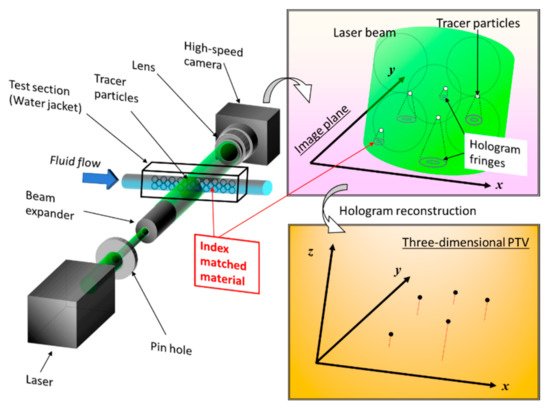
The basic principle of hologram recording is explained here using visualization results for the inside of a tube filled with pebbles made of MEXFLON
[39][43] as an example.
Figure 1 is a schematic showing the composition of DHPTV characterized by the in-line method. Coherent laser light is used as the light source to form a hologram, which is expanded to the observation area using a beam expander. The magnified laser light passes through the test section containing tracer particles. The X–Y–Z position can be determined simultaneously by reconstructing the obtained hologram image on a computer. When a hologram was reproduced, the fringe image of the particle became the substance at the existing focal length of the particle, but came in a focus, and the image was central, and a hole opened, becoming doughnut-shaped. In addition, it grew large so that the size deviated from the focus, and, seen from the side, it was the form such as the hand drum, the fringe image of the particle in the section. Therefore, at each point of the XY plane, the greatest brightness level from all reproduction side of the point was searched. Then, the point was judged as a particle when the biggest brightness level and brightness level of the neighboring pixels of the point about each point were compared, and the greatest brightness level of the point than the brightness level of the neighboring pixels is big, and the value is bigger than the suitable threshold. The velocity vector of the fluid in the measurement volume can be obtained by detecting the moving quantity of the particle and the direction from the three-dimensional particle coordinate between two times provided by the method mentioned above. Multiple hologram images can be continuously processed, and the flow field can be visualized in three dimensions by PTV.
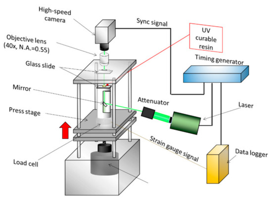
Figure 2 shows measurements of the imprinting process by micro-DHPTV
[40][44]. A technique called UV nano in print lithography (UV-NIL) attracts attention as a core technology of the next-generation semiconductor device process. Ultraviolet rays were irradiated, and this process rigidified resin after transforming a UV-curable resin with a mold. After the resin stiffened, high-speed pattern transcription by separating a mold was performed. However, as in the process of this UV-NIL, lack of filling or lack of hardening of the resin may happen, it was important that the flow of the photocoagulation resin during the process to imprint was measured. Micro-digital holography measurements were performed for the resin crimping process in the imprinting-process apparatus. In the optical axis direction, holographic images were acquired through the crimped glass plates. The flow became a squeezed flow. The flow phenomenon of the UV-curable resin in the imprint process by this distribution was elucidated. By substituting fluorescent particles for the tracking particles in the same macrofluids system,
we successfully themeasured velocity and temperature simultaneously
were successfully measured [41][45]. In recent years, numerous studies have used machine learning to improve the accuracy of holographic processing.
Figure 1. Example of a setting in which DHPTV is applied to an intra-tube flow in a tube filled with MEXFLON pebbles [39]. Example of a setting in which DHPTV is applied to an intra-tube flow in a tube filled with MEXFLON pebbles [43].
Figure 2. DHPTV setting for squeezed flow in a UV nanoimprint process [40]. DHPTV setting for squeezed flow in a UV nanoimprint process [44].